Transcription
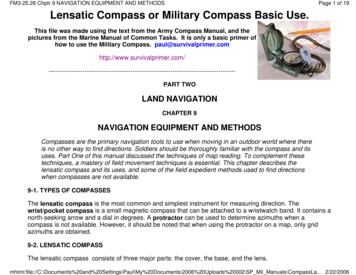
FM3-25.26 Chptr 9 NAVIGATION EQUIPMENT AND METHODSPage 1 of 19Lensatic Compass or Military Compass Basic Use.This file was made using the text from the Army Compass Manual, and thepictures from the Marine Manual of Common Tasks. It is only a basic primer ofhow to use the Military Compass. -----------------------------------------PART TWOLAND NAVIGATIONCHAPTER 9NAVIGATION EQUIPMENT AND METHODSCompasses are the primary navigation tools to use when moving in an outdoor world where thereis no other way to find directions. Soldiers should be thoroughly familiar with the compass and itsuses. Part One of this manual discussed the techniques of map reading. To complement thesetechniques, a mastery of field movement techniques is essential. This chapter describes thelensatic compass and its uses, and some of the field expedient methods used to find directionswhen compasses are not available.9-1. TYPES OF COMPASSESThe lensatic compass is the most common and simplest instrument for measuring direction. Thewrist/pocket compass is a small magnetic compass that can be attached to a wristwatch band. It contains anorth-seeking arrow and a dial in degrees. A protractor can be used to determine azimuths when acompass is not available. However, it should be noted that when using the protractor on a map, only gridazimuths are obtained.9-2. LENSATIC COMPASSThe lensatic compass consists of three major parts: the cover, the base, and the ul\My%20Documents\2006%20Uploads%20002\SP Mil Manuals\CompassLa. 2/22/2006
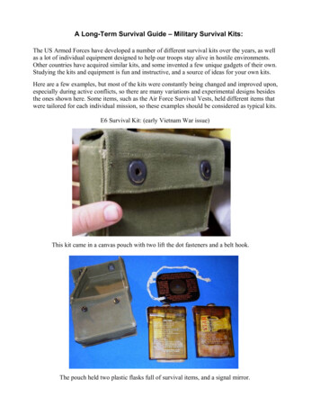
FM3-25.26 Chptr 9 NAVIGATION EQUIPMENT AND METHODSPage 2 of 19Figure 9-1. Lensatic compass.a. Cover. The compass cover protects the floating dial. It contains the sighting wire (front sight) andtwo luminous sighting slots or dots used for night navigation.b. Base. The body of the compass contains the following movable parts:(1) The floating dial is mounted on a pivot so it can rotate freely when the compass is held aul\My%20Documents\2006%20Uploads%20002\SP Mil Manuals\CompassLa. 2/22/2006
FM3-25.26 Chptr 9 NAVIGATION EQUIPMENT AND METHODSPage 3 of 19Printed on the dial in luminous figures are an arrow and the letters E and W. The arrow alwayspoints to magnetic north and the letters fall at east (E) 90 and west (W) 270 on the dial. There aretwo scales; the outer scale denotes mils and the inner scale (normally in red) denotes degrees.(2) Encasing the floating dial is a glass containing a fixed black index line.(3) The bezel ring is a ratchet device that clicks when turned. It contains 120 clicks when rotatedfully; each click is equal to 3 . A short luminous line that is used in conjunction with the northseeking arrow during navigation is contained in the glass face of the bezel ring.(4) The thumb loop is attached to the base of the compass.c. Lens. The lens is used to read the dial, and it contains the rear-sight slot used in conjunction withthe front for sighting on objects. The rear sight also serves as a lock and clamps the dial when closedfor its protection. The rear sight must be opened more than 45 to allow the dial to float freely.NOTE: When opened, the straightedge on the left side of the compass has a coordinatescale; the scale is 1:50,000 in newer compasses.WARNINGSome older compasses will have a 1:25,000 scale. This scale can be usedwith a 1:50,000-scale map, but the values read must be halved. Check thescale.9-3. COMPASS HANDLINGCompasses are delicate instruments and should be cared for accordingly.a. Inspection. A detailed inspection is required when first obtaining and using a compass. One of themost important parts to check is the floating dial, which contains the magnetic needle. The user mustalso make sure the sighting wire is straight, the glass and crystal parts are not broken, the numbers onthe dial are readable, and most important, that the dial does not stick.b. Effects of Metal and Electricity. Metal objects and electrical sources can affect the performance ofa compass. However, nonmagnetic metals and alloys do not affect compass readings. The followingseparation distances are suggested to ensure proper functioning of a \Paul\My%20Documents\2006%20Uploads%20002\SP Mil Manuals\CompassLa. 2/22/2006
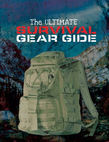
FM3-25.26 Chptr 9 NAVIGATION EQUIPMENT AND METHODSPage 4 of 19High-tension power lines . 55 meters.Field gun, truck, or tank . 18 meters.Telegraph or telephone wires and barbed wire . 10 meters.Machine gun . 2 meters.Steel helmet or rifle . 1/2 meter.c. Accuracy. A compass in good working condition is very accurate. However, a compass has to bechecked periodically on a known line of direction, such as a surveyed azimuth using a declinationstation. Compasses with more than 3 variation should not be used.d. Protection. If traveling with the compass unfolded, make sure the rear sight is fully folded downonto the bezel ring. This will lock the floating dial and prevent vibration, as well as protect the crystal andrear sight from damage.9-4. USING A COMPASSMagnetic azimuths are determined with the use of magnetic instruments, such as lensatic and M2compasses. The techniques employed when using the lensatic compass are as follows:a. Using the Centerhold Technique. First, open the compass to its fullest so that the cover forms astraightedge with the base. Move the lens (rear sight) to the rearmost position, allowing the dial to floatfreely. Next, place your thumb through the thumb loop, form a steady base with your third and fourthfingers, and extend your index finger along the side of the compass. Place the thumb of the other handbetween the lens (rear sight) and the bezel ring; extend the index finger along the remaining side of thecompass, and the remaining fingers around the fingers of the other hand. Pull your elbows firmly intoyour sides; this will place the compass between your chin and your belt. To measure an azimuth, simplyturn your entire body toward the object, pointing the compass cover directly at the object. Once you arepointing at the object, look down and read the azimuth from beneath the fixed black index line . Thispreferred method offers the following advantages over the sighting technique:(1) It is faster and easier to use.(2) It can be used under all conditions of visibility.(3) It can be used when navigating over any type of \Paul\My%20Documents\2006%20Uploads%20002\SP Mil Manuals\CompassLa. 2/22/2006
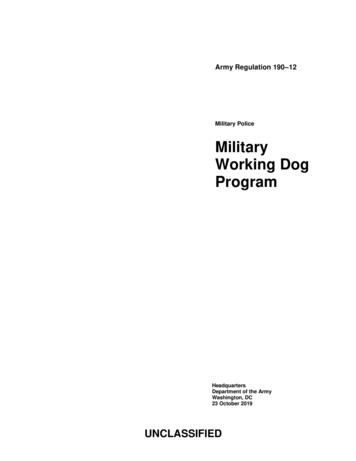
FM3-25.26 Chptr 9 NAVIGATION EQUIPMENT AND METHODSPage 5 of 19(4) It can be used without putting down the rifle; however, the rifle must be slung well back overeither shoulder.(5) It can be used without removing eyeglasses.Figure 9-2. Centerhold technique.b. Using the Compass-to-Cheek Technique. Fold the cover of the compass containing the sightingwire to a vertical position; then fold the rear sight slightly forward. Look through the rear-sight slot andalign the front-sight hairline with the desired object in the distance. Then glance down at the dial throughthe eye lens to read the azimuth .NOTE: The compass-to-cheek technique is used almost exclusively for sighting, and itis the best technique for this \Paul\My%20Documents\2006%20Uploads%20002\SP Mil Manuals\CompassLa. 2/22/2006
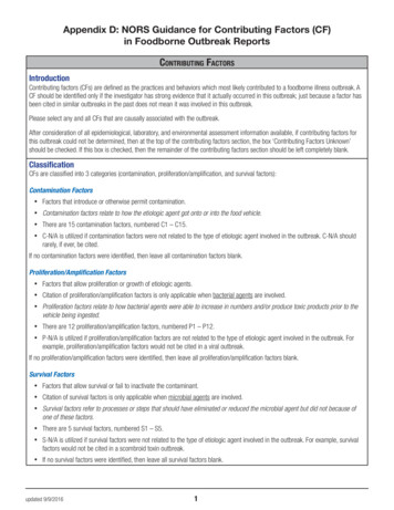
FM3-25.26 Chptr 9 NAVIGATION EQUIPMENT AND METHODSPage 6 of 19Figure 9-3. Compass-to-cheek technique.c. Presetting a Compass and Following an Azimuth. Although different models of the lensaticcompass vary somewhat in the details of their use, the principles are the same.(1) During daylight hours or with a light source:(a) Hold the compass level in the palm of the hand.(b) Rotate it until the desired azimuth falls under the fixed black index line (for example,320 ), maintaining the azimuth as prescribed y%20Documents\2006%20Uploads%20002\SP Mil Manuals\CompassLa. 2/22/2006
FM3-25.26 Chptr 9 NAVIGATION EQUIPMENT AND METHODSPage 7 of 19Figure 9-4. Compass preset at 320 \Paul\My%20Documents\2006%20Uploads%20002\SP Mil Manuals\CompassLa. 2/22/2006
FM3-25.26 Chptr 9 NAVIGATION EQUIPMENT AND METHODSPage 8 of 19(c) Turn the bezel ring until the luminous line is aligned with the north-seeking arrow. Oncethe alignment is obtained, the compass is preset.(d) To follow an azimuth, assume the centerhold technique and turn your body until the northseeking arrow is aligned with the luminous line. Then proceed forward in the direction of thefront cover's sighting wire, which is aligned with the fixed black index line that contains thedesired azimuth.(2) During limited visibility, an azimuth may be set on the compass by the click method.Remember that the bezel ring contains 3 intervals (clicks).(a) Rotate the bezel ring until the luminous line is over the fixed black index line.(b) Find the desired azimuth and divide it by three. The result is the number of clicks that youhave to rotate the bezel ring.(c) Count the desired number of clicks. If the desired azimuth is smaller than 180 , thenumber of clicks on the bezel ring should be counted in a counterclockwise direction. Forexample, the desired azimuth is 51 . Desired azimuth is 51 3 17 clicks counterclockwise. Ifthe desired azimuth is larger than 180 , subtract the number of degrees from 360 and divideby 3 to obtain the number of clicks. Count them in a clockwise direction. For example, thedesired azimuth is 330 ; 360 -330 30 3 10 clicks clockwise.(d) With the compass preset as described above, assume a centerhold technique and rotateyour body until the north-seeking arrow is aligned with the luminous line on the bezel. Thenproceed forward in the direction of the front cover's luminous dots, which are aligned with thefixed black index line containing the azimuth.(e) When the compass is to be used in darkness, an initial azimuth should be set while lightis still available, if possible. With the initial azimuth as a base, any other azimuth that is amultiple of three can be established through the use of the clicking feature of the bezel ring.NOTE: Sometimes the desired azimuth is not exactly divisible by three, causing anoption of rounding up or rounding down. If the azimuth is rounded up, thiscauses an increase in the value of the azimuth, and the object is to be found onthe left. If the azimuth is rounded down, this causes a decrease in the value ofthe azimuth, and the object is to be found on the aul\My%20Documents\2006%20Uploads%20002\SP Mil Manuals\CompassLa. 2/22/2006
FM3-25.26 Chptr 9 NAVIGATION EQUIPMENT AND METHODSPage 9 of 19d. Bypassing an Obstacle. To bypass enemy positions or obstacles and still stay oriented, detouraround the obstacle by moving at right angles for specified distances.(1) For example, while moving on an azimuth of 90 change your azimuth to 180 and travel for100 meters. Change your azimuth to 90 and travel for 150 meters. Change your azimuth to 360 and travel for 100 meters. Then, change your azimuth to 90 and you are back on your originalazimuth line :Figure 9-5. Bypassing an obstacle.(2) Bypassing an unexpected obstacle at night is a fairly simple matter. To make a 90 turn to theright, hold the compass in the centerhold technique; turn until the center of the luminous letter E isunder the luminous line (do not move the bezel ring). To make a 90 turn to the left, turn until \My%20Documents\2006%20Uploads%20002\SP Mil Manuals\CompassLa. 2/22/2006
FM3-25.26 Chptr 9 NAVIGATION EQUIPMENT AND METHODSPage 10 of 19center of the luminous letter W is under the luminous line. This does not require changing thecompass setting (bezel ring), and it ensures accurate 90 turns.e. Offset. A deliberate offset is a planned magnetic deviation to the right or left of an azimuth to anobjective. Use it when the objective is located along or in the vicinity of a linear feature such as a road orstream. Because of errors in the compass or in map reading, the linear feature may be reached withoutknowing whether the objective lies to the right or left. A deliberate offset by a known number of degreesin a known direction compensates for possible errors and ensures that upon reaching the linear feature,the user knows whether to go right or left to reach the objective. Ten degrees is an adequate offset formost tactical uses. Each degree offset moves the course about 18 meters to the right or left for each1,000 meters traveled. For example, below, the number of degrees offset is 10. If the distance traveledto "x" in 1,000 meters, then "x" is located about 180 meters to the right of the objective.This section written by Paul. Note that is is only a basic primer about the military compass. One detail youmight need is the fact that magnetic North differs from true North, well, differently, wherever you are. That isthere is a Magnetic declination, or a difference between the Magnetic North Pole, and the true North ul\My%20Documents\2006%20Uploads%20002\SP Mil Manuals\CompassLa. 2/22/2006
FM3-25.26 Chptr 9 NAVIGATION EQUIPMENT AND METHODSPage 11 of 19There is a difference between true North and magnetic aul\My%20Documents\2006%20Uploads%20002\SP Mil Manuals\CompassLa. 2/22/2006
FM3-25.26 Chptr 9 NAVIGATION EQUIPMENT AND METHODSPage 12 of 19To further confuse, you have what is called grid North. (You just need to know there may be three of themon your maps.) Grid North comes from the fact that you are describing a round Earth on a flat l\My%20Documents\2006%20Uploads%20002\SP Mil Manuals\CompassLa. 2/22/2006
FM3-25.26 Chptr 9 NAVIGATION EQUIPMENT AND METHODSPage 13 of 19Three Norths. True North is noted by a star, Magnetic by N, and Grid by GN.The above facts don't make much difference in simple use of your compass. More used on long voyages, Iam only including them here, for info. To apply, look at the following s\Paul\My%20Documents\2006%20Uploads%20002\SP Mil Manuals\CompassLa. 2/22/2006
FM3-25.26 Chptr 9 NAVIGATION EQUIPMENT AND METHODSPage 14 of My%20Documents\2006%20Uploads%20002\SP Mil Manuals\CompassLa. 2/22/2006
FM3-25.26 Chptr 9 NAVIGATION EQUIPMENT AND METHODSPage 15 of 19The above shows the relationship between what your compass shows, and the other two lines. For practical,short trips in the wild, they make no difference. If you want to head in one direction, and get out by headingin the other, you don't need the other two North's. Another picture, same \Paul\My%20Documents\2006%20Uploads%20002\SP Mil Manuals\CompassLa. 2/22/2006
FM3-25.26 Chptr 9 NAVIGATION EQUIPMENT AND METHODSPage 16 of My%20Documents\2006%20Uploads%20002\SP Mil Manuals\CompassLa. 2/22/2006
FM3-25.26 Chptr 9 NAVIGATION EQUIPMENT AND METHODSPage 17 of 19OK, so I gave you two. Very good pictures of what we are talking about. This file was made using the l\My%20Documents\2006%20Uploads%20002\SP Mil Manuals\CompassLa. 2/22/2006
FM3-25.26 Chptr 9 NAVIGATION EQUIPMENT AND METHODSPage 18 of 19from the Army Compass Manual, and the pictures from the Marine Manual of Common tasks. I hope thathelps. \My%20Documents\2006%20Uploads%20002\SP Mil Manuals\CompassLa. 2/22/2006
FM3-25.26 Chptr 9 NAVIGATION EQUIPMENT AND METHODSPage 19 of My%20Documents\2006%20Uploads%20002\SP Mil Manuals\CompassLa. 2/22/2006
This file was made using the text from the Army Compass Manual, and the pictures from the Marine Manual of Common Tasks. It is only a basic primer of how to use the Military Compass. paul@survivalprimer.com . Part One of this manual discussed the techniques of map reading. To complement the