Transcription
Wave OpticsChapter TenWAVE OPTICS10.1 INTRODUCTIONIn 1637 Descartes gave the corpuscular model of light and derived Snell’slaw. It explained the laws of reflection and refraction of light at an interface.The corpuscular model predicted that if the ray of light (on refraction)bends towards the normal then the speed of light would be greater in thesecond medium. This corpuscular model of light was further developedby Isaac Newton in his famous book entitled OPTICKS and because ofthe tremendous popularity of this book, the corpuscular model is veryoften attributed to Newton.In 1678, the Dutch physicist Christiaan Huygens put forward thewave theory of light – it is this wave model of light that we will discuss inthis chapter. As we will see, the wave model could satisfactorily explainthe phenomena of reflection and refraction; however, it predicted that onrefraction if the wave bends towards the normal then the speed of lightwould be less in the second medium. This is in contradiction to theprediction made by using the corpuscular model of light. It was muchlater confirmed by experiments where it was shown that the speed oflight in water is less than the speed in air confirming the prediction of thewave model; Foucault carried out this experiment in 1850.The wave theory was not readily accepted primarily because of351Newton’s authority and also because light could travel through vacuum2021–22
Physicsand it was felt that a wave would always require a medium to propagatefrom one point to the other. However, when Thomas Young performedhis famous interference experiment in 1801, it was firmly establishedthat light is indeed a wave phenomenon. The wavelength of visiblelight was measured and found to be extremely small; for example, thewavelength of yellow light is about 0.6 µm. Because of the smallnessof the wavelength of visible light (in comparison to the dimensions oftypical mirrors and lenses), light can be assumed to approximatelytravel in straight lines. This is the field of geometrical optics, which wehad discussed in the previous chapter. Indeed, the branch of optics inwhich one completely neglects the finiteness of the wavelength is calledgeometrical optics and a ray is defined as the path of energypropagation in the limit of wavelength tending to zero.After the interference experiment of Young in 1801, for the next 40years or so, many experiments were carried out involving theinterference and diffraction of lightwaves; these experiments could onlybe satisfactorily explained by assuming a wave model of light. Thus,around the middle of the nineteenth century, the wave theory seemedto be very well established. The only major difficulty was that since itwas thought that a wave required a medium for its propagation, howcould light waves propagate through vacuum. This was explainedwhen Maxwell put forward his famous electromagnetic theory of light.Maxwell had developed a set of equations describing the laws ofelectricity and magnetism and using these equations he derived whatis known as the wave equation from which he predicted the existenceof electromagnetic waves*. From the wave equation, Maxwell couldcalculate the speed of electromagnetic waves in free space and he foundthat the theoretical value was very close to the measured value of speedo f l i g h t . F r o m t h i s , h e p r o p o u n d e d t h a t light must be anelectromagnetic wave. Thus, according to Maxwell, light waves areassociated with changing electric and magnetic fields; changing electricfield produces a time and space varying magnetic field and a changingmagnetic field produces a time and space varying electric field. Thechanging electric and magnetic fields result in the propagation ofelectromagnetic waves (or light waves) even in vacuum.In this chapter we will first discuss the original formulation of theHuygens principle and derive the laws of reflection and refraction. InSections 10.4 and 10.5, we will discuss the phenomenon of interferencewhich is based on the principle of superposition. In Section 10.6 wewill discuss the phenomenon of diffraction which is based on HuygensFresnel principle. Finally in Section 10.7 we will discuss thephenomenon of polarisation which is based on the fact that the lightwaves are transverse electromagnetic waves.352* Maxwell had predicted the existence of electromagnetic waves around 1855; itwas much later (around 1890) that Heinrich Hertz produced radiowaves in thelaboratory. J.C. Bose and G. Marconi made practical applications of the Hertzianwaves2021–22
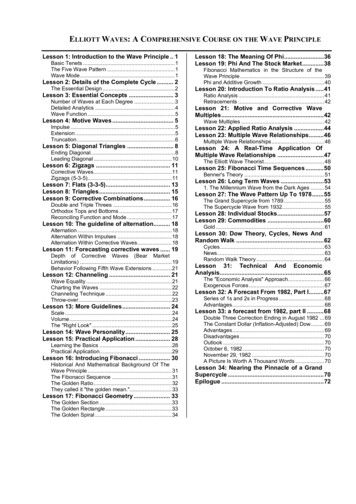
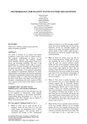
Wave OpticsDOES LIGHT TRAVEL IN A STRAIGHT LINE?Light travels in a straight line in Class VI; it does not do so in Class XII and beyond! Surprised,aren’t you?In school, you are shown an experiment in which you take three cardboards withpinholes in them, place a candle on one side and look from the other side. If the flame of thecandle and the three pinholes are in a straight line, you can see the candle. Even if one ofthem is displaced a little, you cannot see the candle. This proves, so your teacher says,that light travels in a straight line.In the present book, there are two consecutive chapters, one on ray optics and the otheron wave optics. Ray optics is based on rectilinear propagation of light, and deals withmirrors, lenses, reflection, refraction, etc. Then you come to the chapter on wave optics,and you are told that light travels as a wave, that it can bend around objects, it can diffractand interfere, etc.In optical region, light has a wavelength of about half a micrometre. If it encounters anobstacle of about this size, it can bend around it and can be seen on the other side. Thus amicrometre size obstacle will not be able to stop a light ray. If the obstacle is much larger,however, light will not be able to bend to that extent, and will not be seen on the other side.This is a property of a wave in general, and can be seen in sound waves too. The soundwave of our speech has a wavelength of about 50 cm to 1 m. If it meets an obstacle of thesize of a few metres, it bends around it and reaches points behind the obstacle. But when itcomes across a larger obstacle of a few hundred metres, such as a hillock, most of it isreflected and is heard as an echo.Then what about the primary school experiment? What happens there is that when wemove any cardboard, the displacement is of the order of a few millimetres, which is muchlarger than the wavelength of light. Hence the candle cannot be seen. If we are able to moveone of the cardboards by a micrometer or less, light will be able to diffract, and the candlewill still be seen.One could add to the first sentence in this box : It learns how to bend as it grows up!10.2 HUYGENS PRINCIPLEWe would first define a wavefront: when we drop a small stone on a calmpool of water, waves spread out from the point of impact. Every point onthe surface starts oscillating with time. At any instant, a photograph ofthe surface would show circular rings on which the disturbance ismaximum. Clearly, all points on such a circle are oscillating in phasebecause they are at the same distance from the source. Such a locus ofpoints, which oscillate in phase is called a wavefront ; thus a wavefrontis defined as a surface of constant phase. The speed with which thewavefront moves outwards from the source is called the speed of the FIGURE 10.1 (a) Awave. The energy of the wave travels in a direction perpendicular to the diverging sphericalwave emanating fromwavefront.If we have a point source emitting waves uniformly in all directions, a point source. Thewavefronts arethen the locus of points which have the same amplitude and vibrate inspherical.the same phase are spheres and we have what is known as a spherical353wave as shown in Fig. 10.1(a). At a large distance from the source, a2021–22
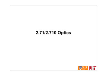
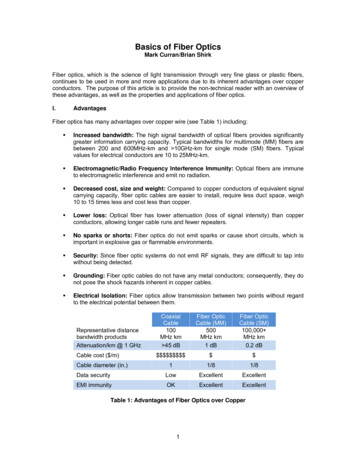
Physicssmall portion of the sphere can be considered as a plane and we havewhat is known as a plane wave [Fig. 10.1(b)].Now, if we know the shape of the wavefront at t 0, then Huygensprinciple allows us to determine the shape of the wavefront at a latertime τ. Thus, Huygens principle is essentially a geometrical construction,which given the shape of the wafefront at any time allows us to determineFIGURE 10.1 (b) At alarge distance from the shape of the wavefront at a later time. Let us consider a divergingthe source, a small wave and let F1F2 represent a portion of the spherical wavefront at t 0(Fig. 10.2). Now, according to Huygens principle, each point of theportion of thespherical wave can wavefront is the source of a secondary disturbance and the waveletsbe approximated by a emanating from these points spread out in all directions with the speedplane wave.of the wave. These wavelets emanating from the wavefront are usuallyreferred to as secondary wavelets and if we draw a common tangentto all these spheres, we obtain the new position of the wavefront at alater time.FIGURE 10.2 F1F2 represents the spherical wavefront (with O ascentre) at t 0. The envelope of the secondary waveletsemanating from F1F2 produces the forward moving wavefront G1G2.The backwave D1D2 does not exist.Thus, if we wish to determine the shape of the wavefront at t τ, wedraw spheres of radius vτ from each point on the spherical wavefrontFIGURE 10.3Huygens geometrical where v represents the speed of the waves in the medium. If we now drawa common tangent to all these spheres, we obtain the new position of theconstruction for awavefront at t τ. The new wavefront shown as G1G2 in Fig. 10.2 is againplane wavespherical with point O as the centre.propagating to theright. F1 F2 is theThe above model has one shortcoming: we also have a backwave whichplane wavefront at is shown as D D in Fig. 10.2. Huygens argued that the amplitude of the1 2t 0 and G1G2 is the secondary wavelets is maximum in the forward direction and zero in thewavefront at a laterbackward direction; by making this adhoc assumption, Huygens couldtime τ. The lines A1A2,explain the absence of the backwave. However, this adhoc assumption isB1B2 etc., arenormal to both F1F2 not satisfactory and the absence of the backwave is really justified frommore rigorous wave theory.and G1G2 andIn a similar manner, we can use Huygens principle to determine therepresent rays.shape of the wavefront for a plane wave propagating through a medium354(Fig. 10.3).2021–22
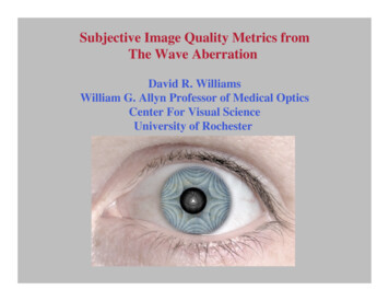
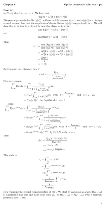
Wave Optics10.3 REFRACTION AND REFLECTION OFP LANE W AVES USING H UYGENSPRINCIPLE10.3.1 Refraction of a plane waveBC v1 τFIGURE 10.4 A plane wave AB is incident at an angle ion the surface PP′ separating medium 1 and medium 2.The plane wave undergoes refraction and CE representsthe refracted wavefront. The figure corresponds to v2 v1so that the refracted waves bends towards the normal.Christiaan Huygens(1629 – 1695) Dutchphysicist, astronomer,mathematician and thefounder of the wavetheory of light. His book,T reatise on light, makesfascinating reading eventoday. He brilliantlyexplained the doublerefraction shown by themineral calcite in thiswork in addition toreflection and refraction.He was the first toanalyse circular andsimple harmonic motionand designed and builtimproved clocks andtelescopes. He discoveredthe true geometry ofSaturn’s rings.CHRISTIAAN HUYGENS (1629 – 1695)We will now use Huygens principle to derive the laws ofrefraction. Let PP′ represent the surface separating medium1 and medium 2, as shown in Fig. 10.4. Let v1 and v2represent the speed of light in medium 1 and medium 2,respectively. We assume a plane wavefront AB propagatingin the direction A′A incident on the interface at an angle ias shown in the figure. Let τ be the time taken by thewavefront to travel the distance BC. Thus,In order to determine the shape of the refracted wavefront, we draw asphere of radius v2τ from the point A in the second medium (the speed ofthe wave in the second medium is v2). Let CE represent a tangent planedrawn from the point C on to the sphere. Then, AE v2 τ and CE wouldrepresent the refracted wavefront. If we now consider the triangles ABCand AEC, we readily obtainsin i BC v1τ AC AC(10.1)andAE v 2τ (10.2)AC ACwhere i and r are the angles of incidence and refraction, respectively.sin r 2021–22355
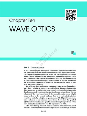
PhysicsThus we obtain(10.3)From the above equation, we get the important result that if r i (i.e.,if the ray bends toward the normal), the speed of the light wave in thesecond medium (v2) will be less then the speed of the light wave in thefirst medium (v1). This prediction is opposite to the prediction from thecorpuscular model of light and as later experiments showed, the predictionof the wave theory is correct. Now, if c represents the speed of light invacuum, then,n1 cv1(10.4)cv2(10.5)andn2 are known as the refractive indices of medium 1 and medium 2,respectively. In terms of the refractive indices, Eq. (10.3) can bewritten asn1 sin i n2 sin r(10.6)This is the Snell’s law of refraction. Further, if λ1 and λ 2 denote thewavelengths of light in medium 1 and medium 2, respectively and if thedistance BC is equal to λ 1 then the distance AE will be equal to λ 2 (becauseif the crest from B has reached C in time τ, then the crest from A shouldhave also reached E in time τ ); thus,http://www.falstad.com/ripple/Demonstration of interference, diffraction, refraction, resonance and Doppler effectsin iv 1sin rv2λ1BCv 1AEλ2v2orv1λ1 v2(10.7)λ2The above equation implies that when a wave gets refracted into adenser medium (v1 v2) the wavelength and the speed of propagationdecrease but the frequency ν ( v/λ) remains the same.10.3.2 Refraction at a rarer mediumWe now consider refraction of a plane wave at a rarer medium, i.e.,v2 v1. Proceeding in an exactly similar manner we can construct arefracted wavefront as shown in Fig. 10.5. The angle of refractionwill now be greater than angle of incidence; however, we will still haven1 sin i n2 sin r . We define an angle ic by the following equationn2(10.8)n1Thus, if i ic then sin r 1 and r 90 . Obviously, for i ic, there cannot be any refracted wave. The angle ic is known as the critical angle andfor all angles of incidence greater than the critical angle, we will not havesin i c 3562021–22
Wave Opticsany refracted wave and the wave will undergo what is known as totalinternal reflection. The phenomenon of total internal reflection and itsapplications was discussed in Section 9.4.FIGURE 10.5 Refraction of a plane wave incident on a rarer medium forwhich v2 v1. The plane wave bends away from the normal.10.3.3 Reflection of a plane wave by a plane surfaceWe next consider a plane wave AB incident at an angle i on a reflectingsurface MN. If v represents the speed of the wave in the medium and if τrepresents the time taken by the wavefront to advance from the point Bto C then the distanceBC vτIn order to construct the reflected wavefront we draw a sphere of radiusvτ from the point A as shown in Fig. 10.6. Let CE represent the tangentplane drawn from the point C to this sphere. ObviouslyAE BC vτFIGURE 10.6 Reflection of a plane wave AB by the reflecting surface MN.AB and CE represent incident and reflected wavefronts.If we now consider the triangles EAC and BAC we will find that theyare congruent and therefore, the angles i and r (as shown in Fig. 10.6)would be equal. This is the law of reflection.Once we have the laws of reflection and refraction, the behaviour ofprisms, lenses, and mirrors can be understood. These phenomena were2021–22357
Physicsdiscussed in detail in Chapter 9 on the basis of rectilinear propagation oflight. Here we just describe the behaviour of the wavefronts as theyundergo reflection or refraction. In Fig. 10.7(a) we consider a plane wavepassing through a thin prism. Clearly, since the speed of light waves isless in glass, the lower portion of the incoming wavefront (which travelsthrough the greatest thickness of glass) will get delayed resulting in a tiltin the emerging wavefront as shown in the figure. In Fig. 10.7(b) weconsider a plane wave incident on a thin convex lens; the central part ofthe incident plane wave traverses the thickest portion of the lens and isdelayed the most. The emerging wavefront has a depression at the centreand therefore the wavefront becomes spherical and converges to the pointF which is known as the focus. In Fig. 10.7(c) a plane wave is incident ona concave mirror and on reflection we have a spherical wave convergingto the focal point F. In a similar manner, we can understand refractionand reflection by concave lenses and convex mirrors.FIGURE 10.7 Refraction of a plane wave by (a) a thin prism, (b) a convex lens. (c) Reflection of aplane wave by a concave mirror.From the above discussion it follows that the total time taken from apoint on the object to the corresponding point on the image is the samemeasured along any ray. For example, when a convex lens focusses lightto form a real image, although the ray going through the centre traversesa shorter path, but because of the slower speed in glass, the time takenis the same as for rays travelling near the edge of the lens.10.3.4 The doppler effect358We should mention here that one should be careful in constructing thewavefronts if the source (or the observer) is moving. For example, if thereis no medium and the source moves away from the observer, then laterwavefronts have to travel a greater distance to reach the observer andhence take a longer time. The time taken between the arrival of twosuccessive wavefronts is hence longer at the observer than it is at thesource. Thus, when the source moves away from the observer thefrequency as measured by the source will be smaller. This is known asthe Doppler effect. Astronomers call the increase in wavelength due todoppler effect as red shift since a wavelength in the middle of the visibleregion of the spectrum moves towards the red end of the spectrum. Whenwaves are received from a source moving towards the observer, there isan apparent decrease in wavelength, this is referred to as blue shift.2021–22
Wave OpticsYou have already encountered Doppler effect for sound waves inChapter 15 of Class XI textbook. For velocities small compared to thespeed of light, we can use the same formulae which we use for soundwaves. The fractional change in frequency ν/ν is given by –vradial/c, wherevradial is the component of the source velocity along the line joining theobserver to the source relative to the observer; vradial is considered positivewhen the source moves away from the observer. Thus, the Doppler shiftcan be expressed as: νν –vradialc(10.9)The formula given above is valid only when the speed of the source issmall compared to that of light. A more accurate formula for the Dopplereffect which is valid even when the speeds are close to that of light, requiresthe use of Einstein’s special theory of relativity. The Doppler effect forlight is very important in astronomy. It is the basis for the measurementsof the radial velocities of distant galaxies.Example 10.1 What speed should a galaxy move with respectto us so that the sodium line at 589.0 nm is observedat 589.6 nm?Solution Since νλ c, νν – λλ(for small changes in ν and λ). For λ 589.6 – 589.0 0.6 nmwe get [using Eq. (10.9)] νν – λλ –vradialc 306 km/sTherefore, the galaxy is moving away from us.Solution(a) Reflection and refraction arise through interaction of incident lightwith the atomic constituents of matter. Atoms may be viewed as2021–22EXAMPLE 10.2Example 10.2(a) When monochromatic light is incident on a surface separatingtwo media, the reflected and refracted light both have the samefrequency as the incident frequency. Explain why?(b) When light travels from a rarer to a denser medium, the speeddecreases. Does the reduction in speed imply a reduction in theenergy carried by the light wave?(c) In the wave picture of light, intensity of light is determined by thesquare of the amplitude of the wave. What determines the intensityof light in the photon picture of light.EXAMPLE 10.1 0.6 5–1or, vradial c 3.06 10 m s589.0 359
EXAMPLE 10.2Physicsoscillators, which take up the frequency of the external agency (light)causing forced oscillations. The frequency of light emitted by a chargedoscillator equals its frequency of oscillation. Thus, the frequency ofscattered light equals the frequency of incident light.(b) No. Energy carried by a wave depends on the amplitude of thewave, not on the speed of wave propagation.(c) For a given frequency, intensity of light in the photon picture isdetermined by the number of photons crossing an unit area perunit time.10.4 COHERENT AND INCOHERENT ADDITION OF WAVES(a)In this section we will discuss the interference pattern produced bythe superposition of two waves. You may recall that we had discussedthe superposition principle in Chapter 15 of your Class XI textbook.Indeed the entire field of interference is based on the superpositionprinciple according to which at a particular point in the medium, theresultant displacement produced by a number of waves is the vectorsum of the displacements produced by each of the waves.Consider two needles S1 and S2 moving periodically up and downin an identical fashion in a trough of water [Fig. 10.8(a)]. They producetwo water waves, and at a particular point, the phase difference betweenthe displacements produced by each of the waves does not changewith time; when this happens the two sources are said to be coherent.Figure 10.8(b) shows the position of crests (solid circles) and troughs(dashed circles) at a given instant of time. Consider a point P for whichS1 P S2 P(b)FIGURE 10.8 (a) Twoneedles oscillating inphase in waterrepresent two coherentsources.(b) The pattern ofdisplacement of watermolecules at aninstant on the surfaceof water showing nodalN (no displacement)and antinodal A(maximumdisplacement) lines.360Since the distances S1 P and S2 P are equal, waves from S1 and S2will take the same time to travel to the point P and waves that emanatefrom S1 and S2 in phase will also arrive, at the point P, in phase.Thus, if the displacement produced by the source S1 at the point Pis given byy1 a cos ωtthen, the displacement produced by the source S2 (at the point P) willalso be given byy2 a cos ωtThus, the resultant of displacement at P would be given byy y1 y2 2 a cos ωtSince the intensity is proportional to the square of the amplitude,the resultant intensity will be given byI 4 I0where I0 represents the intensity produced by each one of the individualsources; I0 is proportional to a2. In fact at any point on the perpendicularbisector of S1S2, the intensity will be 4I0. The two sources are said to2021–22
Wave Opticsinterfere constructively and we have what is referred to as constructiveinterference. We next consider a point Q [Fig. 10.9(a)]for whichS2Q –S1Q 2λThe waves emanating from S1 will arrive exactly two cycles earlierthan the waves from S2 and will again be in phase [Fig. 10.9(a)]. Thus, ifthe displacement produced by S1 is given byy1 a cos ωtthen the displacement produced by S2 will be given byy2 a cos (ωt – 4π) a cos ωtwhere we have used the fact that a path difference of 2λ corresponds to aphase difference of 4π. The two displacements are once again in phaseand the intensity will again be 4 I0 giving rise to constructive interference.In the above analysis we have assumed that the distances S1Q and S2Qare much greater than d (which represents the distance between S1 andS2) so that although S1Q and S2Q are not equal, the amplitudes of thedisplacement produced by each wave are very nearly the same.We next consider a point R [Fig. 10.9(b)] for whichFIGURE 10.9(a) ConstructiveThe waves emanating from S1 will arrive exactly two and a half cyclesinterference at alater than the waves from S2 [Fig. 10.10(b)]. Thus if the displacement point Q for which thepath difference is 2λ.produced by S1 is given by(b) Destructivey1 a cos ωtinterference at apoint R for which thethen the displacement produced by S2 will be given bypath difference isy2 a cos (ωt 5π) – a cos ωt2.5 λ .S2R – S1R –2.5λwhere we have used the fact that a path difference of 2.5λ corresponds toa phase difference of 5π. The two displacements are now out of phaseand the two displacements will cancel out to give zero intensity. This isreferred to as destructive interference.To summarise: If we have two coherent sources S1 and S2 vibratingin phase, then for an arbitrary point P whenever the path difference,S1P S2P nλ(n 0, 1, 2, 3,.)(10.10)we will have constructive interference and the resultant intensity will be4I0; the sign between S1P and S2 P represents the difference betweenS1P and S2 P. On the other hand, if the point P is such that the pathdifference,1) λ (n 0, 1, 2, 3, .)(10.11)2FIGURE 10.10 Locuswe will have destructive interference and the resultant intensity will be of points for whichzero. Now, for any other arbitrary point G (Fig. 10.10) let the phase S P – S P is equal to12difference between the two displacements be φ. Thus, if the displacementzero, λ, 2λ, 3λ .produced by S1 is given byS1P S2P (n 361y1 a cos ωt2021–22
Physicsthen, the displacement produced by S2 would bey2 a cos (ωt φ )and the resultant displacement will be given byy y1 y2 a [cos ωt cos (ωt φ ve-interferenceRipple Tank experiments on wave interference 2 a cos (φ/2) cos (ωt φ/2)The amplitude of the resultant displacement is 2a cos (φ/2) andtherefore the intensity at that point will beI 4 I0 cos2 (φ/2)(10.12)If φ 0, 2 π, 4 π, which corresponds to the condition given byEq. (10.10) we will have constructive interference leading to maximumintensity. On the other hand, if φ π, 3π, 5π [which corresponds tothe condition given by Eq. (10.11)] we will have destructive interferenceleading to zero intensity.Now if the two sources are coherent (i.e., if the two needles are goingup and down regularly) then the phase difference φ at any point will notchange with time and we will have a stable interference pattern; i.e., thepositions of maxima and minima will not change with time. However, ifthe two needles do not maintain a constant phase difference, then theinterference pattern will also change with time and, if the phase differencechanges very rapidly with time, the positions of maxima and minima willalso vary rapidly with time and we will see a “time-averaged” intensitydistribution. When this happens, we will observe an average intensitythat will be given by I 4I 0 cos2 (φ/2 ) (10.13)where angular brackets represent time averaging. Indeed it is shown inSection 7.2 that if φ (t ) varies randomly with time, the time-averagedquantity cos2 (φ/2) will be 1/2. This is also intuitively obvious becausethe function cos2 (φ/2) will randomly vary between 0 and 1 and theaverage value will be 1/2. The resultant intensity will be given byI 2 I0(10.14)at all points.When the phase difference between the two vibrating sources changesrapidly with time, we say that the two sources are incoherent and whenthis happens the intensities just add up. This is indeed what happenswhen two separate light sources illuminate a wall.10.5 INTERFERENCEEXPERIMENT362OFLIGHT WAVESANDYOUNG’SWe will now discuss interference using light waves. If we use two sodiumlamps illuminating two pinholes (Fig. 10.11) we will not observe anyinterference fringes. This is because of the fact that the light wave emittedfrom an ordinary source (like a sodium lamp) undergoes abrupt phase2021–22
Wave Opticschanges in times of the order of 10–10 seconds. Thusthe light waves coming out from two independentsources of light will not have any fixed phaserelationship and would be incoherent, when thishappens, as discussed in the previous section, theintensities on the screen will add up.The British physicist Thomas Young used aningenious technique to “lock” the phases of the wavesemanating from S1 and S2. He made two pinholes S1FIGURE 10.11 If two sodiumand S2 (very close to each other) on an opaque screenlamps illuminate two pinholes[Fig. 10.12(a)]. These were illuminated by anotherS1 and S2, the intensities will addpinholes that was in turn, lit by a bright source. Lightup and no interference fringes willbe observed on the screen.waves spread out from S and fall on both S1 and S2.S1 and S2 then behave like two coherent sourcesbecause light waves coming out from S1 and S2 are derived from thesame original source and any abrupt phase change in S will manifest inexactly similar phase changes in the light coming out from S1 and S2.Thus, the two sources S1 and S2 will be locked in phase; i.e., they will becoherent like the two vibrating needle in our water wave example[Fig. 10.8(a)].(a)(b)FIGURE 10.12 Young’s arrangement to produce interference pattern.Thus spherical waves emanating from S1 and S2 will produceinterference fringes on the screen GG′, as shown in Fig. 10.12(b). Thepositions of maximum and minimum intensities can be calculated byusing the analysis given in Section 10.4 where we had shown that for anarbitrary point P on the line GG′ [Fig. 10.12(b)] to correspond to amaximum, we must haveS2P – S1P n λ; n 0, 1, 2 .(10.15)Now,22 2 d d 2 –D x–Dx (S2P ) – (S1P ) 2 2x d2 222021–22363
Physicswhere S1S2 d and OP x. ThusTHOMAS YOUNG (1773 – 1829)S2P – S1P (10.16)If x, d D then negligible error will be introduced ifS2P S1P (in the denominator) is replaced by 2D. Forexample, for d 0.1 cm, D 100 cm, OP 1 cm (whichcorrespond to typical values for an interferenceexperiment using light waves), we haveThomasYoung(1773 – 1829) Englishphysicist, physician andEgyptologist. Young workedon a wide variety ofscientific problems, rangingfrom the structure of the eyeand the mechanism ofvision to the deciphermentof the Rosetta stone. Herevived the wave theory oflight and recognised thatinterference phenomenaprovide pr
The sound wave of our speech has a wavelength of about 5 0cm to 1 m. If it meets an obstacle of the size of a few metres, it bends around it and reaches points behind the obstacle. But when it comes across a larger obstacle