Transcription
A MODEL OF NUTRIENT FLOW IN ANAQUAPONICS SYSTEM A WARRENSFORDA SENIOR RESEARCH PAPER PRESENTED TO THE DEPARTMENTOF MATHEMATICS AND COMPUTER SCIENCE OF STETSONUNIVERSITY IN PARTIAL FULFILLMENT OF THE REQUIREMENTSFOR THE DEGREE OF BACHELOR OF SCIENCESTETSON UNIVERSITY2015
ACKNOWLEDGMENTSI would like to thank my advisor, Dr. William Miles, for all of his helpthroughout the semester. I would also like to thank Dr. Harry Price forassistance with the chemistry concepts related to this project, and Dr. ErichFriedman for help with Mathematica.
Contents1 Abstract12 Background2.1 Advantages of Aquaponic Gardening . . . . . . . . . . . . . .2.2 System Design . . . . . . . . . . . . . . . . . . . . . . . . . . .1133 Derivation of the Model3.1 Derivation of the DAR Equation . . . . . . . . . . . . . . . .3.2 Nonhomogenous Terms . . . . . . . . . . . . . . . . . . . . .3.3 Flow Fields . . . . . . . . . . . . . . . . . . . . . . . . . . .3.4 DAR Equations, Initial Conditions, and Boundary Conditionsfor each Substance . . . . . . . . . . . . . . . . . . . . . . .4. 4. 9. 11. 154 Estimation of Parameters184.1 The Plant Uptake Function . . . . . . . . . . . . . . . . . . . 184.2 The Fish Excretion Function . . . . . . . . . . . . . . . . . . . 214.3 Additional Parameters . . . . . . . . . . . . . . . . . . . . . . 235 Numerical Methods276 Future Plans947 Appendix7.1 The Nonlinear Regression for Fish Excretion Data . . . . . .7.2 Original Fish Excretion Data . . . . . . . . . . . . . . . . .7.3 The Parameter Table for Plant Uptake of Nitrogen . . . . .7.4 An Example of Restrictions on Explicit Numerical Methods7.5 The WENO Scheme . . . . . . . . . . . . . . . . . . . . . .7.6 The Third Order TVDRK Method . . . . . . . . . . . . . .References.96969799100102104106
1AbstractAquaponics is a combination of hydroponics (growing plants in a soillessenvironment) and aquaculture (raising fish in a tank). As a byproduct ofrespiration, fish excrete toxic ammonia from their gills. In an aquaponicssystem, the water in the fish tank is pumped to beds where plants are grownin a soilless medium. Nitrifying bacteria colonize in the medium, and convertammonia to nitrite and then nitrate. The plants can readily absorb thenitrate as a vital nutrient, and the water, which is now free of the toxicammonia and nitrite, is pumped back to the fish tank. In this paper, wewill attempt to simulate nutrient flow in an aquaponics system with a twodimensional model. For each of the three substances of interest: ammonia,nitrite, and nitrate; a diffusion-advection-reaction equation will be used todetermine its concentration within the fish tank and plant bed as a functionof time and space. Model parameters will be estimated based on empiricalevidence, and we will discuss possible numerical methods that could be usedto solve the equations in our model.22.1BackgroundAdvantages of Aquaponic GardeningAquaponics not only combines hydroponics and aquaculture; it is an improvement upon each system. In aquaculture, solid fish excrement and ammoniaproduced during respiration must be filtered out of the water and discarded.Aquaponics makes use of these waste products as nutrients for the plants(Bernstein 6-7). Similarly, hydroponics requires growers to use costly manufactured nutrient solutions. For the same cost in fish feed, aquaponic gardeners can grow approximately the same number of plants as hydroponicgardeners, as well as several pounds of fish. Moreover, water in a hydroponicsystem must be thrown out periodically because chemicals accumulate totoxic levels. Water is never discarded in an aquaponics system (Bernstein 4).Aquaponics wastes much less water than traditional or hydroponic gardeningbecause the nutrient solution is continually circulated between the fish tankand plant bed. Thus water is only lost when it evaporates or is taken up byfish and plants (Bernstein 2). In addition, research conducted by Dr. NickSavidov in 2005 showed that aquaponics has a higher yield than hydroponics.1
He was able to grow 10-15% more tomatoes than are grown on average ina hydroponics setup. Furthermore, Savidov achieved a threefold increase inplant production within two years (Savidov 20, 24). It is also worth mentioning that since nutrients for the plants come from fish, aquaponics producesorganic products, while hydroponically grown plants are clearly not organic(Bernstein 5).Aquaponics is a novel way for the human race to stop using more natural resources than the earth can replenish. Demographers predict that thepopulation will increase by an average of 75 million people each year until2050 (Bernstein 11). According to the World Wildlife Funds Living PlanetReport in 2008, the current population already exceeds the planets regenerative capacity by about 30 percent (Bernstein 12). As China and India, thetwo countries with the largest populations, continue to raise their standardof living to that of the United States, this shortage of resources will only getworse.Aquaponics eliminates many aspects of agriculture, such as excessive landand water use, that make it unsustainable. In 2009, United Nations DeputySecretary-General Asha-Rose Migiro projected that two-thirds of the earth’spopulation will go without water within twenty years (Bernstein 15). Inthe U.S., 80% of the water we use is for agriculture; hence it is easy tosee why a recirculating agricultural system would be of value (Bernstein15). Furthermore, everyone knows that deforestation is a major problem;over 40% of the earth’s land has been cleared for agriculture (Bernstein 18).Thus less trees are available to turn carbon dioxide into oxygen, and therebyreduce greenhouse gas emissions. Soilless agriculture such as aquaponics isclearly a way to diminish this problem.In addition, aquaponics could reduce overfishing. At least 2,048 speciesof fish are extinct because of overfishing (Bernstein 18). If we farm more fishinstead of catching them, then in time maybe less species of fish would beendangered. Moreover, fish are a much more efficient animal to farm thanmost traditional farm animals. Fish convert about 67% of their food weightto body weight gain; whereas chickens, pigs, cows, and sheep only convertroughly 50%, 25%, 15%, and 13%, respectively (Bernstein 19). Aquaponicshas the potential to generate a large amount of nutritious food with a lowimpact on the environment.2
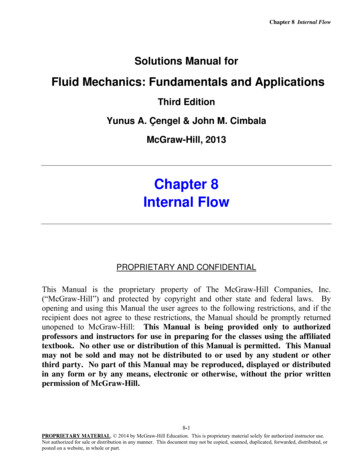
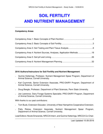
2.2System DesignThere are many different ways to construct an aquaponics system. The threemajor techniques are the deep water culture (DWC) method, the nutrientfilm technique (NFT), and media-based aquaponics. For both DWC andNFT, water flows from the fish tank through a filter that traps solid fishwaste, and then to a sump tank that contains a biofilter for nitrification (asump is just a tank that holds excess water in an aquaponics system) (Designof Aquaponic Units 64, 68). A typical biofilter would be plastic netting thatencloses PVC pipe shavings; the shavings create adequate surface area forbacteria to colonize. The biofilter must also have an aerator because thebacteria need oxygen to survive (Design of Aquaponic Units 46). From thesump tank, some water is pumped back to the fish tank, and the rest goesto the plants. The water that returns to the fish tank forces it to overflowinto the filter again. After the water flows through the compartments thatcontain the plants, it also goes back to the sump tank (Design of AquaponicUnits 64). For DWC, plants are placed in holes on a floating polystyrene raftso that their roots are submerged in the nutrient-rich water pumped fromthe sump. For NFT, plants are placed in holes that are drilled into pipes.A small amount of water from the sump tank flows through the pipes andbathes the roots (Design of Aquaponic Units 48, 49).The major downside to DWC and NFT is that a mechanical filter and anaerated biofilter are required, whereas in media-based aquaponics the mediain which the plants grow acts as a biofilter and filters solid waste (Design ofAquaponic Units 45). Furthermore, DWC is mainly limited to small plantslike lettuce and herbs; larger plants are too heavy to float in rafts (Design ofAquaponic Units 73). Additional aeration is also required in the plant canalsfor DWC because plants take up dissolved oxygen (DO) from the water. Thewater is relatively stagnant beneath the rafts, and thus does not containenough DO to support the plants’ needs. These are not problems in mediabased aquaponics because the flooding and draining of the bed allows oxygento reach plant roots and bacteria, and any plant that thrives in neutral pHcan be grown (Bernstein 110, 153). For these reasons, we choose to modelbasic flood and drain media-based aquaponics, which is shown in figure 1(Bernstein 98).3
Figure 1: Basic Flood and Drain Media-Based Aquaponics33.1Derivation of the ModelDerivation of the DAR EquationIn this model, the fish tank is represented by a rectangular region in thefirst quadrant of the x-y plane, with one corner at the origin, O. Likewise,the plant bed is represented by a rectangular region in the x̌-y̌ plane, withone corner at the origin, Ǒ. The length of the fish tank in the x-directionis lF ; its height in the y-direction is hF . The length of the plant bed inthe x̌-direction is lP ; its height in the y̌-direction is hP . It should be notedthat these heights are not the actual heights of the tank and bed, but ratherthe maximum height that water ever reaches throughout the flood and draincycle. Symmetry is assumed for the third dimension of each compartment.In other words, the tank and bed are rectangular boxes, and the nutrient flowwithin each cross-section parallel to the x-y and x̌-y̌ planes, respectively, areassumed to be the same. The widths of the fish tank and plant bed are wFand wP , respectively. Obviously, this set-up is somewhat unrealistic becausepipe openings typically occupy a small circular region of space; whereas ourassumptions of symmetry require rectangular pipe openings of infinitessimallength and widths equal to the widths of the compartments that contain thepipe openings. However, this notion is not so far-fetched when one considersthat gardeners frequently drill holes along the sides of PVC pipes to sendwater to multiple locations within the plant bed or increase the DO in thefish tank by creating turbulent flow. The pump is located at O, and is4
connected to a pipe that opens at Ǒ. The overflow pipe has openings at(lP , hP ) in the x̌-y̌ plane and (lF , hF ) in the x-y plane. We assume that inthe actual aquaponics setup the plant bed is above the fish tank so thatduring overflow water enters the fish tank at (lF , hF ) in the x-y plane.At time t 0, the pump turns on, and water is pumped from the fishtank to the plant bed at a rate vp . When t t̂, the water has reached themaximum desired height hP in the plant bed, and water begins to flow fromthe plant bed to the fish tank via the overflow pipe. This maintains the waterlevel in the plant bed at hP until time t t̃ when the pump shuts off. Thenthe water in the plant bed drains back through the pump at a rate v̂p untilthe bed contains no water; this occurs at t t̄. Until the pump turns backon at t t , there is no water flow between the tank and the bed (Bernstein98).To model the concentrations of ammonia, nitrite, and nitrate as a functionof time and space, we will use diffusion-advection-reaction (DAR) equations.Diffusion, advection, and reaction are the mechanisms by which concentration changes with time. Diffusion is the tendency of solutes to move fromregions of high concentration to those with a lower concentration. This resultsfrom the random movement of molecules in the fluid. When concentration isconstant throughout a solution, collisions between molecules send the samenumber of particles, on average, in all directions. Thus concentration doesnot change over time. However, when concentration varies with respect tolocation in a fluid, the regions of higher concentration tend to expel moreparticles of solute than regions of lower concentration (de Marsily 232). Theresult, is an overall tendency toward uniform concentration. Advection isthe process by which chemicals dissolved in a fluid are transported by themovement of the fluid; reaction describes the the consumption or productionof solutes by chemical reactions (de Marsily 230).Consider the concentration of ammonia, denoted by Ǎ Ǎ(x̌, y̌, t), in theplant bed. Since the medium consists of gravel or a similar material, it canbe treated as porous with porosity ω (Bernstein 111). Porosity is the fractionof the plant bed through which water can flow, i.e. the portion that is notoccupied by gravel (Logan 30). We assume that ω is constant throughout theplant bed. This is reasonable because all the pieces of gravel are similar insize to one another. Furthermore, when fish waste starts to clog up regionsin the medium, the gardener must either clean out the plant bed or includered wriggler worms in the bed. These worms break down solid waste, whichprevents clogging (Bernstein 178-9). We also assume that all of the spaces5
between pieces of gravel are filled with water at all times (Logan 30). Ofcourse, this contradicts the fill and drain action within the plant bed, but wecan always solve the DAR equation for small intervals of time for which thedecrease in water level is negligible.The DAR equation for ammonia in the plant bed can be derived fromThe Principle of Mass Balance, which states that the rate of change of themass within an arbitrary volume in a region is equal to the rate at whichthe substance crosses the boundary of the volume plus the rate at which it iscreated or distroyed within the volume (Logan 31). Let Ω denote the regionin R3 that is occupied by the plant bed. Let Ω0 be an arbitrary ball in Ωwith surface Ω0 . The outward unit vector that is normal to Ω0 is denoted by n̂. Let Q(x̌,y̌, t) denote the rate of flow (mass per unit time) across Ω0 . is the flux of ammonia. Let R(x̌, y̌, t) be the rate at whichIn other words, Qammonia is produced or destroyed in Ω0 . Mathematically, mass balance canbe stated as equation (1) (Logan 35).ZZZ R dτ(1)Q · n̂ da ω Ǎ dτ t Ω0Ω0 Ω0The left hand side of equation (1) is the rate of change of the total massof ammonia within the ball. Notice that ω is included in the integrand onthe left side. This is because for each infinitessimal volume element dτ , onlya fraction of the volume (ωdτ ) is available for water to flow through. Also · n̂ is positive when ammonia is flowing out of Ω0 . Therefore,observe that Qthe amount of ammonia in the arbitrary ball decreases when the flux integralis positive. Thus we must place a negative sign in front of the flux integral inequation (1). Furthermore, even though there is no flow in the ž-direction, can be written as a three-dimensional vector with a ž-component that isQzero. Hence it can be dotted with n̂. The second term on the right side isthe rate at which ammonia is consumed during nitrification within the ball(Logan 31).If Ǎ and Ǎ/ t are continuous over Ω0 , then we can bring the partialderivative inside the integrand in equation (1). Furthermore, using the divergence theorem, the surface integral in equation (1) can be rewritten as avolume integral. The divergence theorem is stated below (Calculus: EarlyTranscendentals 1129).The Divergence Theorem : Let E be a simple solid region and let S6
be the boundary surface of E, given with positive (outward) orientation.Let F be a vector field whose component functions have continuous partialderivatives on an open region that contains E. ThenZZ · F dτF · dS SEBy observing that d a da n̂, equation (1) can be rewritten asZZ Ǎ dτ · Q dτ R dτω tΩ0Ω0Ω0 Z Ǎ ω · Q R dτ 0 tΩ0 Ǎ ω · Q R 0, (x̌, y̌) Ω, t 0 tZ(2)The last line above follows from the fact that Ω0 is arbitrary. The onlyway that the volume integral can equal zero for any ball Ω0 is if the integrandis identically zero. Also note that though the Del operator does not have the is”ˇ” accent, the derivatives are with respect to x̌ and y̌. The form of Qbased on experimental evidence; it is the sum of the advective flux, molecular (a) resultsdiffusion flux, and dispersion flux. Recall that the advective flux Qfrom particles being transported by the movement of water (Logan 32). It isgiven by (a) V p ǍQ(3)The vector field V p is the velocity field of the water in the plant bed, with (m) isunits of length over time. As we stated, the molecular diffusion flux Qdue to molecules colliding with each other (Logan 32). By Fick’s Law, (m) ωD(m) ǍQ(4)The coefficient D(m) is the effective molecular diffusion coefficient in themedium; it is only 10-70% as large as Do , the usual molecular diffusioncoefficent. Do is defined for a stagnant fluid with no boundaries. Finally, (d) results from the fluid traveling more quickly throughthe dispersion flux Qsome paths in the medium than others (Logan 32). Again, according toFick’s Law,7
(d) ωD(d) ǍQ(5)The coefficient D(d) is the dispersion coefficient (Logan 33). Thereforethe total flux is given by V p Ǎ ωD(m) Ǎ ωD(d) ǍQ Ǎ V p Ǎ ωD (6)The coefficient D is the hydrodynamic dispersion coefficient; it is thesum of the effective molecular diffusion and dispersion coefficients (Logan equation (2) can be written as33). With this form for Q, Ǎ Ǎ] R 0 · [Vp Ǎ ωD (7) tFor now, we will assume that D is constant within the grow bed. Inreality, the component of D in the direction of flow is much larger than thecomponents of D perpendicular to the flow field (de Marsily 236). This willbe discussed in detail later when we talk about choosing reasonable parametervalues. Therefore,ωω Ǎ · (Vp Ǎ) ωD 2 Ǎ R 0 t(8)If we let φ̌ and ψ̌ be the x̌- and y̌- components of the flow field, respectively, then (Ǎφ̌) (Ǎψ̌) x̌ y̌ Ǎ φ̌ Ǎ ψ̌ φ̌ Ǎ ψ̌ Ǎ x̌ x̌ y̌ y̌ Ǎ Ǎ φ̌ ψ̌ φ̌ ψ̌ Ǎ Ǎ x̌ y̌ x̌ y̌ Ǎ) · V p Ǎ( · V p ) ( · (V p Ǎ) Thus,8(9)
Ǎ Ǎ) · V p Ǎ( · V p )] ωD 2 Ǎ R 0 [( t Ǎ Ǎ) ω 1 Ǎ( · V p ) ω 1 R D 2 Ǎ ω 1 V p · ( tω(10)Equation (10) is the DAR equation for Ammonia within the plant bed.Notice that Ǎ does not depend on ž and the ž- component of V is zerobecause there is no flow in the ž-direction. Therefore, the Laplacian andgradient in equation (10) are two-dimensional for this model. The concentrations of nitrite and nitrate in the fish tank will be represented by B̌ and Č,respectively. The DAR equations for these substances in the plant bed havethe same form as the equation for ammonia. In the fish tank, the equationsfor each substance are derived in exactly the same manner as for the plantbed, except the fish tank does not contain a porous medium. Consequently,the diffusion coefficient is assumed to be Do (though there are boundariesand the water is not still), and the entire volume in the fish tank is availableto water. Hence, the concentration of ammonia, A, in the fish tank is givenby A · V F ) R Do 2 A V F · ( A) A( t(11)where V F is now the flow field in the fish tank. The concentrations ofnitrite and nitrate in the fish tank will be represented by B and C, respectively. The DAR equations for these substances in the fish tank have thesame form as the equation for ammonia.3.2Nonhomogenous TermsThe reaction term R varies depending on the substance and its locationwithin the aquaponics system. In the plant bed, R will describe the rate ofchange of concentration due to nitrification. The chemical reaction equationsfor nitrification are given below (”Wastewater Management.” 1).N H3 O2 N O2 3H 2e N O2 H2 O N O3 2H 2e 9(12)(13)
Essentially, these equations state that ammonia (N H3 ) transforms intonitrite (N O2 ), which then transforms into nitrate (N O3 ). Ammonia is converted to nitrite mainly by the bacteria Nitrosomonas sp.; nitrite is transformed into nitrate mostly by Nitrobacter sp. bacteria (Tyson 20). TheChemical Law of Mass Action given below states that the rate at which aproduct is created (or a reactant is consumed) is proportional to the productof the concentrations of the reactants (”Reaction Kinetics.” 2).The Chemical Law of Mass Action13 : If a chemical reaction is givenbya b c,thend[b]d[c]d[a] k[a][b] ,dtdtdtwhere [u] denotes the concentration of substance u.However, we can assume that oxygen (O2 ) and water (H2 O) are at muchhigher concentrations than ammonia and nitrite. This is reasonable becauseammonia and nitrite are dissolved in a large amount of water in the plantbed. Also, the plant bed is well-oxygenated due to the flood and drain process. Hence, the percentages of oxygen and water consumed by the reactionwill be negligible compared to their total concentrations. With minimalerror, we can assume that the concentrations of oxygen and water remainconstant throughout the reaction. Therefore, these concentrations can beabsorbed into the constants of proportionality (Copeland 479). Thus therates of change of the concentrations of ammonia, nitrite, and nitrate due tonitrification are given bydǍ k1 ǍdtdB̌ k1 Ǎ k2 B̌dtdČ k2 B̌dt(14)(15)(16)The constants k1 and k2 are called the rate constants for equations (12)and (13), respectively. There are negative signs in equations (14) and (15)10
because as the concentrations of the reactants increase, the reaction speedsup, and reactants are consumed faster. The right-hand sides of equations(14), (15), and (16) are reaction terms for ammonia, nitrite, and nitrate,respectively, in the plant bed.In addition to the reaction term given by equation (16), the DAR equationfor nitrate in the plant bed will include another source (or more accuratelydrain) term P (C) that describes plant uptake of nitrate. Plants also takeup ammonia, but they take up far less ammonia than nitrate. Later, whenwe discuss parameter values, we will prove empirically that plant uptake ofammonia is negligible. Very little nitrification occurs in the fish tank becauseit does not contain a biofilter. Therefore, equations (14) - (16) do not applyin the fish tank. The only source term present in the fish tank is F (t), whichdescribes the fish ammonia excretion. We will approximate P and F laterusing experimental evidence.3.3Flow FieldsAdvection in the fish tank and plant bed is determined by the velocity fieldof the water during each stage of the flood and drain process. During the F and V P U P .period when the plant bed is filling with water, let V F U To simulate fluid flow in the fish tank, UF has a sink at the location of thepump so that the velocity vector at each point in the tank points toward the F approaches vp as the distance from the pump approachespump, and Uzero.As the distance from the pump approaches the maximum distance ofp F approaches zero. ThuslF2 h2F , we assume that U!p2 y2x x, y F vp 1 ppV F U22lF hFx2 y 2!11 vp p 2 p x, y , 0 t t̂ (17)lF h2Fx2 y 2 F is has an infiniteOf course, this creates a removable discontinuity;Upp22 magnitude at the origin, and UF vp (1 x̌ y̌ / lF2 h2F ) elsewhere.This is okay, since we are only concerned with fluid flow within the tank.When we numerically solve the DAR equations, we can exclude the origin P has a source at the origin where waterfrom our mesh. In the plant bed, U P approaches vp as the distanceflows into the bed. As in the fish tank, U11
P approaches zero asfrom the origin approaches zero, and we assume that Upthe distance from the pump approaches the maximum distance of lP2 h2P .Hence,px̌2 y̌ 2! x̌, y̌ p x̌2 y̌ 2!11p x̌, y̌ , 0 t t̂ (18) p2lP h2Px̌2 y̌ 2 P vpV P U vp1 plP2h2PDuring the period of overflow, V F has a sink at the origin and a source at(lF , hF ), where water from the overflow pipe flows in. Notice that the rateof inflow must equal the rate of outflow so that the water level in the plantbed is maintained at hp . This implies that!p22 x lF , y hF F vp p x ypV F U, t̂ t t̃(19)22(x lF )2 (y hF )2lF hFSimilarly, V P has a source at the origin and a sink at (lP , hP ). Hence,!p2 y̌ 2x̌ l x̌, hP y̌ P vp pp PV P U, t̂ t t̃(20)22(x̌ lP )2 (y̌ hP )2lP hPWhile the plant bed is draining, V F has a source at the origin where waterflows back through the pump. Similarly, V P has a sink at the origin. Therefore V P and V F approach vˆp as the distance from the origin approaches approach zero as the distance from the originzero. Again,p VP and VFpapproaches lP2 h2P and lF2 h2F , respectively. This yieldsV F vˆpV P vˆp1px2 y 21plP2 h2P1 p!lF2 h2F1 px̌2 y̌ 2 x, y , t̃ t t̄(21) x̌, y̌ , t̃ t t̄(22)!Finally, for t̄ t t , the plant bed is completely drained. Thus,V P V F 0 until the pump turns on again. These velocity fields assume12
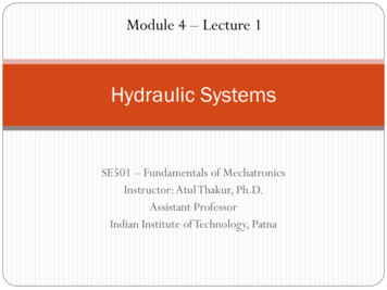
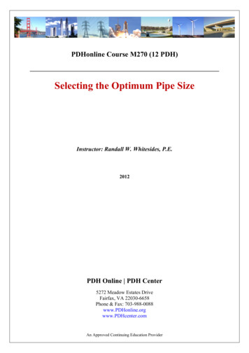
that flow within the tank and the bed is only affected by water flowingbetween the tanks. This is fairly accurate for the plant bed; though theporosity of the medium will cause some deviation from the expected flowpattern; However, this assumption is somewhat inaccurate in the fish tank.Fish generally require highly oxygenated water, thus aerators and air stonesare often placed in the fish tank to increase the DO. This creates turbulence,which we have decided to ignore for the purposes of this model. Plots ofthe flow fields are shown in figures 2 - 4. The lengths and heights chosenfor the fish tank and plant bed in these figures are based upon physicalconsiderations that will be discussed when we estimate parameters.Figure 2: The velocity fields in the fish tank (left) and plant bed (right) for0 t t̂.13
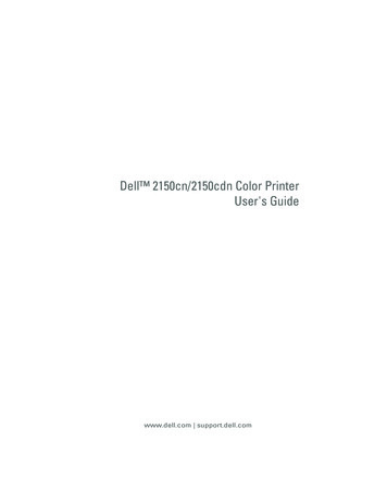
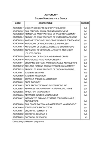
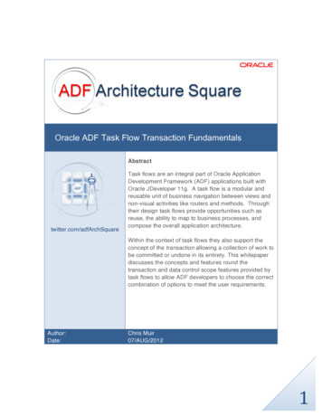
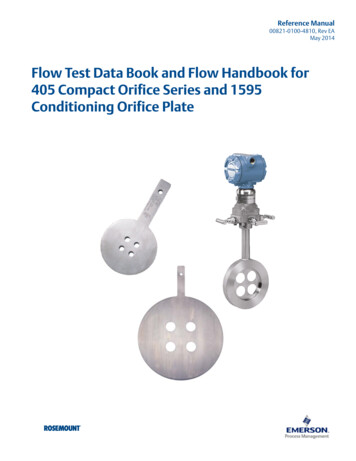
Figure 3: The velocity fields in the fish tank (left) and plant bed (right) fort̂ t t̃.Figure 4: The velocity fields in the fish tank (left) and plant bed (right) fort̃ t t̄.14
3.4DAR Equations, Initial Conditions, and BoundaryConditions for each SubstanceNow we are ready to write out the DAR equations for each substance ofinterest. Each substance will have its own hydrodynamic dispersion coefficient in the plant bed. The dispersion coefficients for ammonia, nitrite, andPPnitrate are DA, DB, DCP , respectively. Likewise, each substance has its ownmolecular diffusion coefficient in the fish tank. The diffusion coefficients forFFammonia, nitrite, and nitrate in the plant bed are DA, DB, DCF , respectively.Therefore, the DAR equations in the Fish Tank (0 x lF , 0 y hF )for 0 t t̄ are AF 2 DA A V F t BF 2 DB B V F t C DCF 2 C V F t A( · V F ) F (t)· A(23) B( · V F )· B(24) C( · V F )· C(25)Similarly, the equations in the Plant Bed (0 x lP , 0 y hP ) for0 t t̄ are written as ǍP 2 DA Ǎ ω 1 V P t B̌P 2 DB B̌ ω 1 V P tk2 B̌) Č DCP 2 Č ω 1 V P tω 1 P (x̌, y̌, t) Ǎ ω 1 Ǎ( · V P ) ω 1 k1 Ǎ· (26) B̌ ω 1 B̌( · V P ) ω 1 (k1 Ǎ · (27) Č ω 1 Č( · V P ) ω 1 k2 B̌ · (28)When t̄ t t , Ǎ B̌ Č 0 in the plant bed because the bed isdrained (we are ignoring the small amount of water contained in the porousmedium). In the fish tank, the water is assumed to be stagnant and the fishare still excreting ammonia. Hence the concentrations of the nitrogenous15
compounds are given by AF 2 DA A F (t) t BF 2 B DB t C DCF 2 C t(29)(30)(31)Later we will show that, due to the flood-and-drain process, there aresome values of y and y̌ that are not valid during each time period. This occursbecause the DAR equations are only valid in domains that are completelyfilled with water (in the plant bed this means that every void in the porousmedium is filled with water).For each substance and each boundary in the tank and bed, we havezero-flux (Neumann) boundary conditions (BCs). This makes sense becausenone of our substances of interest are dissolving into the water from the airabove each compartment. Furthermore, material cannot diffuse or advectacross the walls of these containers, which are typically plastic or some otherimpermeable material. For 0 t t̂, we have a source at Ǒ and a corresponding drain at O. Thus we will impose a Dirichlet BC by solving theequations for the fish tank first, and then requiring that the concentrationat Ǒ equal the concentration at O. This implies that the BCs for ammoniawhen 0 t t̂ are given by A x Ǎ x̌ A y Ǎ y̌Ǎ 0 for x 0, 0 y yJ and x lF , 0 y yJ(32) 0 for x̌ 0, 0 y̌ yˇL and x̌ lP , 0 y̌ yˇL(33) 0 for y 0, 0 x lF and y yJ , 0 x lF(34) 0 for y̌ 0, 0 x̌ lP and y̌ yˇL , 0 x̌ lP(35) A for x y x̌ y̌ 0(36)where yJ (t) and y̌L (t) are the heights of the water in the fish tank andplant bed, respectively. Notice that these heights vary depending on whichpart of the flood and drain cycle we are in. These heights will be found for16
each time period when we define our computational grid in the numericalmethods section. When the water in the plant bed drains back through thepump (t̃ t t̄), the BCs are the same except we must find the solution inthe plant bed first so that we have enough information to satisfy equation(36). For the overflow period (t̂ t t̃), the BCs are the same except wemust also impose a Dirichlet BC where the plant bed overflows into the fishtank. Hence for t̂ t t̃,A(lF , yJ , t) Ǎ(lP , hP , t)(37)During the period when the plant bed is empty, the BCs are the same asthose given by equations (32) - (35), except there is no Dirichlet BC at theorigin; all BCs are zero-flux. The BCs for the DAR equations for nitrite andnitrate are the same as for ammonia during each time period. It should benoted that when we impose these BCs n
Aquaponics is a combination of hydroponics (growing plants in a soilless environment) and aquaculture (raising sh in a tank). As a byproduct of respiration, sh excrete toxic ammonia from their gills. In an aquaponics system, the water in the sh tank is pu