Transcription
Copyright 2006 KSAE1229 9138/2006/028 15International Journal of Automotive Technology, Vol. 7, No. 4, pp. 509 517 (2006)OVERVIEW OF TELEMATICS: A SYSTEM ARCHITECTUREAPPROACHK. Y. CHO , C. H. BAE , Y. CHU and M. W. SUH1)1)2)3)*Graduated School of Mechanical Engineering, Sungkyunkwan University, Gyeonggi 440-746, KoreaElectrical and Computer Engineering Department, Mississippi State University, Box 9571,Mississippi State, MS 39762, USASchool of Mechanical Engineering, Sungkyunkwan University, Gyeonggi 440-746, Korea1)2)3)(Received 25 January 2004; Revised 28 December 2005)ABSTRACT In the mid 1990s, the combination of vehicles and communication was expected to bolster the stagnant carindustry by offering a flood of new revenues. In-vehicle computing systems provide safety and control systems needed tooperate the vehicle as well as infotainment, edutainment, entertainment, and mobile commerce services in a safe andresponsible manner. Since 1980 the word “telematics” has meant the blending of telecommunications and informatics.Lately, telematics has been used more and more to mean “automotive telematics” which use informatics andtelecommunications to enhance the functionality of motor vehicles such as wireless data applications, intelligent cruisecontrol, and GPS in vehicles. This definition identifies telecommunications transferring information as the key enablingtechnology to provide these advanced services. In this paper, a possible framework for future telematics, which is calledan Intelligent Vehicle Network (IVN), is proposed. The paper also introduces and compares a number of existingtechnologies and the terms of their capabilities to support a suite of services. The paper additionally the paper suggests andanalyzes possible directions for future telematics from current telematics techniques.KEY WORDS : Vehicle telematics, Intelligent vehicle network, In-vehicle network architecture1. INTRODUCTIONand what constitutes a telematics-enabled automobile.Since 1980 the word “telematics” has meant the blendingof telecommunications and informatics (Zhao, 2002).This definition identifies telecommunications transferringinformation as the key enabling technology to providethese advanced services. Also from a hardware standpoint we expect, in general, the following conditions arerequired for future telematics (Mattias, 1998):Telematics technologies might indeed deliver an enticingvariety of in-vehicle services, which may still revolutionizethe experience of driving. Telematics may help carmakersobtain an ongoing revenue stream and help regulatorsprogress towards intelligent transportation system andtheir associated benefits of pollution reduction, reducedtransit times, and reduced road fatalities. Also for consumers there should be an effective service price reduction via economies of scope and the less quantifiablebenefits associated with access to safety and securityservices. There is a very interesting report published byATX Technologies about customers’ desire for advancedtechnologies (Wallace, 2000). Through surveying theirtelematics subscribers, ATX Technologies confirmed thepopularity of telematics systems. Approximately 70percent of the subscribers indicated they would ask atelematics system on their next vehicle. Over 80 percentwould recommend the telematics system to a friend oracquaintance.It is important to understand the definition of telematics In-vehicle processor with application programs. Bus-based or wireless networking. Safety unit and dynamic navigation. Self-diagnostic device with user-friendly interfaces. Enterainment and multimedia devices. Emergency support, etc.In this paper, we introduce current telematics technologies and propose a possible framework for futuretelematics, which is called Intelligent Vehicle Network(IVN). For current technologies, we introduce and compare a number of existing technologies and the terms oftheir capabilities to support suitable services. In addition,the paper suggests and analyzes possible directions forfuture telematics from current telematics techniques.*Corresponding author. e-mail: suhmw@yurim.skku.ac.kr509
510K. Y. CHO, C. H. BAE, Y. CHU and M. W. SUHThe structure of this paper is as follows: In section2 which is composed into four sub-sections, we introduceand compare a number of existing technologies and theterms of their capabilities to support a suite of services;A possible framework for future telematics, which iscalled an Intelligent Vehicle Network (IVN), proposed inthis paper is discussed in section 3; and section 4 suggestsand analyzes possible directions for future telematicsfrom current telematics techniques and concludes thisstudy.2. CURRENT TELEMATICS TECHNOLOGIESIn this section, we introduce and compare a number ofexisting technologies and the terms of their capabilities tosupport suitable services. These technologies can begenerally divided into four parts, in-vehicle networking(IN), intelligent transport system for driver’s safety,vehicle diagnostics system, and in-vehicle entertainmentsystem.2.1. In-vehicle Networking (IN)Many vehicles already have a large number of electroniccontrol systems. The growth of vehicle electronics ispartly the result of the customer’s wish for better safetyand greater comfort. And it is partly the result of thegovernment’s requirements for improved emission controland reduced fuel consumption. The complexity of thefunctions implemented in these systems needs an exchangeof the data between each device. With conventionalsystems complex (William, 1997), data isexchanged by means of dedicated signal lines, but this isbecoming increasingly difficult and expensive as controlfunctions become ever more. Moreover, a number ofsystems are being developed that implement functionscovering more than one control device. For overcomingthese problems, various methods have been carriedout.The candidate protocols of IN should satisfy theconditions, which are simple wire, easy to use, wideapplication range, flexibility and low cost.In the following, the protocol, which is developed orbeing developed, is introduced and compared by terms ofits characteristics and advantages.etal.2.1.1. D2B (Domestic Digital Bus)Philips Consumer Electronics developed Domestic DigitalBus, or D2B for short, in 1988, and the standard waspublished in 1991. Originally developed with home audioin mind, it later became apparent that D2B was suitablefor in-car use (Sweeney, 2002).D2B Transfer Technology has the advantage of lowcost, no interference and reliable operation, and noquality loss of the signal.2.1.2. BluetoothBluetooth is a short-range general-purpose wireless networking standard. Originally intended as a wire replacementfor connections between computers, PDA (personal digitalassistants), cell phones, and other devices, it has grown tobecome a personal area network (PAN) standard theapplications of which grow daily (Khan, 2001).Bluetooth Transfer Technology has the advantage oflow cost, low power, good at Wide Area Network (WAN)/Local Area Network (LAN) access points, support bothvoice and data, and operate in a license free band 2.45GHz (Chaari, 2002).et al.2.1.3. CAN (Controller Area Network)CAN, Controller Area Network, is a serial bus systemdesigned for networking ‘intelligent’ devices as well assensors and actuators within a system. CAN was originally developed for passenger car applications. CAN is aserial bus system with multi-master capabilities, whichmeans that all CAN nodes are able to transmit data andseveral CAN nodes can request the bus simultaneously.The serial bus system with real-time capabilities is thesubject of the ISO 11898 international standard andcovers the lowest two layers of the ISO/OSI referencemodel (Wense, 2000).CAN protocol has the advantage of very little cost andeffort to expend on personal training, low-cost controllerchips can be employed in data link, and high transmissionreliability/Short reaction times.2.1.4. LIN (Local Interconnect Network)In June 1999, five major European car manufacturers,one semiconductor supplier, and one tool vendor agreedon a specification for a class - multiplex protocol calledLIN (Local Interconnect Network) (MOST Cooperation,1999).LIN message structure has the advantage of onlymaster node determines scheduling, no arbitration takesplace, schedule determined by a table, and latency &transmission are well known.2.1.5. MOST (Media Oriented Systems Transport)MOST, Media Oriented Systems Transport, was developed in conjunction with DaimlerChrysler, Becker, BMW,and Oasis beginning in 1997. It can be looked at as asuccessor of D2B even though D2B is an independentsystem that will continue in other applications. With theever-increasing number of devices in vehicles, it wasapparent that a new form of data transfer had to bedeveloped to cope, and MOST is the result (Parnell,2003).MOST protocol has the advantage of ease of use, wideapplication range, synchronous bandwidth, asynchronousbandwidth, flexibility, synergy with consumer and PC
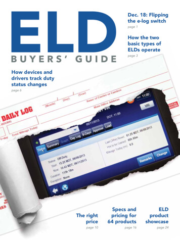
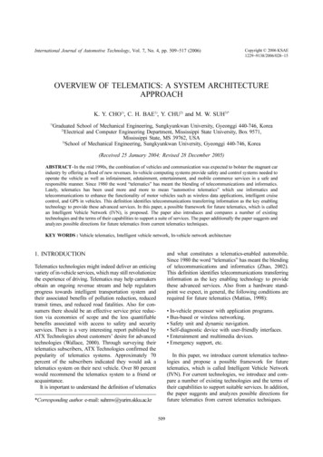
OVERVIEW OF TELEMATICS: A SYSTEM ARCHITECTURE APPROACH511industry, low implementation cost, and open systemsinterconnect reference model.module's definition and detail content is described at thefollowing paragraphs.2.1.6. IDB-1394The IDB (Internal Data Bus) Form manages the IDB-C,IDB-1394 buses, and standard IDB interfaces for OEMsfor the development of after-market and portable devices.Based on the CAN bus, IDB-C is geared toward deviceswith data rates of 250 Kbps. Applications for IDB-Cinclude connectivity through consumer devices such asdigital phones, PDAs, and audio systems (Hadeler andMathony, 2000).2.2.1. The positioning modulePositioning information is obtained by multi-sensor integration and fusion. Each sensor has its own capabilitiesand independent failures. The reason for multi-sensorintegration and fusion is to compensate for the failures.The positioning module is based on GPS (global positioning system) system (Guo., 2001) and DeadReckoning (Redmill., 2001; Calafell., 2000)data fused via filtering methods such as Kalman filters.Dead-Reckoning (DR) method and GPS systems operatetogether to compensate for their failures because the DRmethod uses relative positioning techniques and GPS thesystem is absolute positioning techniques. The positioning module is very important in the N.A.I.C.C. system,because most accurate vehicle positioning is bestperformance of the N.A.I.C.C. system. Therefore, thefusion algorithm (Lauffenburger., 2000) has beenimplemented for accurate vehicle positioning. Thefundamental concept of fusion algorithm increasesaccuracy by using the DR method when DifferentialGlobal Positioning System (DGPS) is used in aninappropriate environment. In other words, this algorithmuses the DGPS data when the signals are available andswitches to the DR method when the number of visiblesatellites is not sufficient to ensure an accurate position.2.1.7. System comparisonThe requirements with respect to data transfer rate,protocol mechanism, reliability, fault tolerance, and costsare dependent of their applications and have led to thedevelopment and introduction of different network types.Figure 1 shows the characteristics of in-vehicle networks(Juliussen, 2003).2.2. Intelligent Transport SystemIn the field of vehicle telematics, an intelligent transportsystem project has been developed to improve thedriver's safety and driving comfort on any type of roads.This section introduces N.A.I.C.C. (Navigation AidedIntelligent Cruise Control) system that is presented by(Lauffenburger, 2000). Generally, the purpose of anN.A.I.C.C. system is the driver alarm and the velocitycontrol. In order to achieve this purpose, the N.A.I.C.C.system is based on a positioning module, a map-matchingalgorithm, a digital map database, a real-time velocityestimator, and a speed prediction module.The appropriate speed can be predicted by consideringthe road characteristics. When the appropriate speed iscalculated, the constraints are provided data such asdriving style and speed reference. The sensors mountedon the vehicle and the real-time velocity estimatorprovides some information to the constraints. Eachet al.Figure 1. Characteristics of in-vehicle networks.etalet alet alet al2.2.2. The digital map databaseIn the N.A.I.C.C. system, the digital map database(Claussen, 1993) is an important system that relates tomatching the trajectory and the known road or determining the optimal speed. The road curvature providedby the digital map database is used to determine whetherthe vehicle is located on a straight road or not and topredict the optimal speed. The Bezier curves approximation method (Venhovens., 1999) allows aparametric description of the curve. This approximationmethod enables any type of curve to be defined.Therefore, the storage memory for a digital map databaseis not important compared with a traditional databasestructure. The basic concept of approximation is toconsider every road as a bend, a straight line having aparticular bend with an infinite radius of curvature.etal2.2.3. The map-matching moduleAs presented in section 2.2.1 the fusion algorithmswitches to the DR method when the DGPS is notsufficient to ensure an accurate position. Once the DRmethod is active, the system will gather an accumulativeerror. Thus, the DR position must match the nearest pointon the digital map. The map-matching module for theN.A.I.C.C. system is based on an algorithm using only
512K. Y. CHO, C. H. BAE, Y. CHU and M. W. SUHgeometric information called Geometric Point-to-PointMatching. The basic concept of Geometric Point-to-PointMatching is to match the point provided by the positioning module to the nearest point of a Bezier curve in thedigital map database. This is more efficient than atraditional point-to-point algorithm because it is onlynecessary to calculate the distance between the deadreckoned point and each point in the database to find thenearest point (Caves., 1991).et al2.2.4. The speed prediction moduleAs shown earlier, the purpose of the N.A.I.C.C. system isthe driver alarm and the velocity control. The optimalspeed predicted by the speed prediction module (Holzmann., 1997) is compared with the estimated vehiclespeed, and the system warns the driver of an inappropriate speed. At the same time, the system automaticallyadjusts the vehicle speed via a cruise control system(Ioannou., 1993). The speed prediction modulerequires some specific information to calculate theappropriate speed. Finally, the determination of thevelocity is modeled by a finite state machine and adaptedto the N.A.I.C.C. system.The N.A.I.C.C system will play an important role inthe future, not only to assess macroscopic traffic situations, but also to build microscopic road geometrydatabases. Communication technologies with an appropriate bandwidth, latency, and coverage need to bedeveloped in order to enable the N.A.I.C.C. On the GPSside, there is a clear need for accurate low-cost receiversin combination with an extensive network of differentialcorrections.etaletal2.3. Vehicle Diagnostics SystemVehicle diagnostics systems have been developed asdesign controls for system faults, which may result infailure modes. The final goal of diagnostics systems is toprovide to the vehicle the best possible performance of allthe electronics systems placed in the vehicle. Low costdisplays and processors allow sophisticated diagnosticsinformation to be accessed and displayed in the vehiclewithout requiring additional service-bay tools. In addition,inexpensive wireless wide-area networks allow remoteaccess to the vehicle’s electronic systems and thus allowfor services such as predictive maintenance (Cirilo.,2000). This section introduces architecture of remotediagnostics system.et al2.3.1. The vehicle electronic architecture & diagnosticssystemThe vehicle electronic architecture (Amberkar.,2000) has two modules. An engine control module isresponsible for capturing the electric signals of thesensors’ management and the ideal amount of fuel to beetalinjected on the exact moment through the time ofopening and closing of the injection valves. Anothermodule is responsible for receiving the electronic signalsof the footpedal accelerator and also of providing otherfunctions of the cabin, such as engine brake, power takeoff, management of the sent or received information fromthe instrument cluster, and others. Besides, these modulescan also interact with other existent ECU (ElectronicControl Unit)’s in the electronic architecture responsibleto manage specific functions of the vehicle, such asbrakes, maintenance, gearbox and retarders, doorcontrols and immobilizers.In general, vehicle diagnostic systems are composed ofan on-board diagnostic system, an off-board diagnosticsystem, and wireless communications. The on-boarddiagnostic system (Shultz., 2002) performs presentation of diagnostics information to the vehicle operator,other telematics applications, transmission of vehicleinformation, reactions to updates of vehicle parameters,and maintenance of security for access to vehiclediagnostic systems. Thus, the vehicle diagnostic systemrequires access to vehicle information that is providedfrom a data bus on-board the vehicle. The off-boarddiagnostic system gives necessary information to performa preventive and corrective maintenance of the vehicle inthe workshop. In the off-board diagnostic system, muchdiagnosis information requires more technical knowledge. Wireless communication is used to interfacebetween the on-board and off-board diagnostic systemfor vehicle diagnostic systems. The progress of wirelesscommunication increases the capabilities of vehicles toself-diagnose known failure modes that they have beenpre-programmed to detect.et al2.3.2. Architecture of integrated diagnostics systemArchitecture of integrated diagnostics system (Campos, 2002) is composed of the enterprise, application, andclient.The enterprise data layer is composed of the vehiclespecific configuration database, vehicle diagnostic content database, and the vehicle test specification database.These databases support the lower level diagnostic applications. The lower level diagnostic applications need tointerface with other enterprise information systems. Inorder to interface with other enterprise informationsystems, the J2EE (Borland, 2003) framework provides aconnector API (Application Program Interface), which isused to create adapters to provide common access to theenterprise layer. The enterprise data layer also capturesthe summary data that is being collected from all of thediagnostic sessions. Thus, the diagnostics experientialdatabase contains not only the information about thesymptoms of a vehicle problem, but also a history of thediagnostic steps. This information can be used to opti-etal.
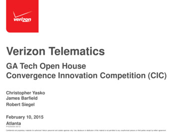
OVERVIEW OF TELEMATICS: A SYSTEM ARCHITECTURE APPROACHmize the diagnostic processes that are used to resolvefuture problems.The application server layer performs hosting diagnosticapplications, managing diagnostic sessions, sending diagnostic bundles to diagnostic clients, pre-processing andsending configuration data to the client-side diagnosticapplications, downloading configuration data to vehicleprocessors, and downloading new software to vehicle onboard processors. The remote diagnostic scenario is asubset of the total diagnostics infrastructure needed tosupport the vehicle fleet during its lifecycle. For theremote diagnostics scenario, the diagnostic applicationdeveloper will have to perform a trade-off between onboard and off-board processing. The obvious benefit ofthis architecture is that every unit in the fleet couldreceive a software update without having to return to thebase location.Client devices and applications perform hosting onboard diagnostic applications, executing diagnostic bundlesdelivered from the remote server, reading data fromprocessors on the vehicle data bus, sending data to theremote server, writing configuration parameters to processors on the vehicle data bus, downloading new software to vehicle processors, and commanding processorsto actuate devices under their control. The client architecture provides secure and controlled access to the vehicledata bus through the implementation of custom bundlesfor server messaging and vehicle communications interface.Vehicle diagnostics systems may be the most important telematics application for the auto manufacturersbecause vehicle diagnostics system has potential savingsin operational cost, warranty cost, and design improvements.2.4. In-vehicle Entertainment SystemAn in-vehicle entertainment system (Schopp andTeichner, 1999) is a system integrator that displays dataefficiently for the driver and other passengers. The input513data include navigation information from a GPS andmaps, entertainment systems, mobile phones, and insome regions, road-tolling systems, that can be updated.The output data include driver and passenger screens andaudio.An in-vehicle entertainment system must include trafficinformation systems, Internet/Web access, electronic gameconsoles, mpeg music download capability, digital radioreception, and mobile commerce services. The opticalbus system enables further integration of computingfunctions and computing applications, which requireinteractivity for Internet access and games. These applications can be connected via gateways to PC platforms.A gateway is a router between the different electrical andoptical buses in a vehicle. Gateways to the optical busmay connect the mobile phone, the media changer, thenavigation unit and other devices to a PC in the vehicle,at the same time may give displays for the front and rearseats access to the PC unit.An in-vehicle entertainment controller is composed ofprocessor, telematics, interface, and entertainment, asshown Figure 2. The processor provides all of the controlfunctions of the system. The GPS, wheel sensors, andtachometer interfaces receive navigational, wheel-speed,and engine-speed information and pass it to the LCDgraphics controller for display. The entertainment unitprovides access to the automobile's CD-ROM player,where MP3 music files are stored. The system's navigational data, as used by the GPS system, can also be storedhere. MP3 music files are sent to the automobile's audiosystem for playback via the audio interface. The interfaceunit provides the controller access to all of the automobile's driver-information and entertainment systems,such as the on-board-computer, via the Ethernet interface.3. INTELLEGENT VEHICLE NETWORK(IVN)In this paper, a possible framework for future telematics,which is called an Intelligent Vehicle Network (IVN), isFigure 2. Configuration of the in-vehicle entertainment system.
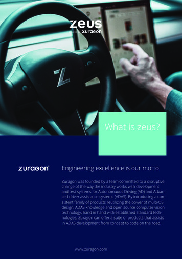
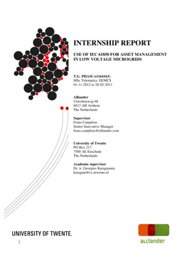
514K. Y. CHO, C. H. BAE, Y. CHU and M. W. SUHFigure 3. Intelligent vehicle network.and wireless Web connection, it also displays/announcesinformation of a vehicle’s conditions and controls a subunit’s behavior.The detailed conditions required for an MCU areshown in Figure 4. That is, the interface to the sub-unitsis always made through an in-vehicle network connection. The format of the requests and responses arestandardized.Defining the interface as a network connection makesthe interface programming independent and flexible.Because the software life cycle is shorter than a vehicle’s,the MCU can be upgraded easily after installation throughwireless communication. The communication with thedriver must be supported by various methods, such as auser-friendly graphic interface and voice recognition.In the Table 1, the platforms Microsoft Car.Net andSun Microsystems Java platform are introduced (Rogers., 2000). Figure 5 shows the concept of relationshipbetween MCU and Adaptive Network Architecture (ANA).et al3.2. Adaptive Network ArchitectureThis section describes the overall architecture of anadaptive network. The fast improvement of the networkshas led to the change of service from text based mediaapplications to multimedia applications. In these conditions, two factors should be considered.Firstly, service specific network environment shouldbe provided. According to a media type, different transmit systems and different levels of Quality of Service(QoS) are used. Secondly, networks should have anFigure 4. The requirement of master control unit.proposed. The IVN consists of a Master Control Unit(MCU), an Adaptive Network Architecture (ANA), anIn-vehicle network, a User Friendly Diagnosis (UFD)unit, a safety unit, and an entertainment unit. Figure 3shows the relationship between units.3.1. Master Control Unit (MCU)In this section, a description is given of MCU, which is aplatform of the telematics systems that manages manycustomized services such as information, entertainment,Figure 5. Master control unit & adaptive networkarchitecture.Table 1. The comparison of car.net and java.The Microsoft Car.Net platform A potential platform for delivering Telematics applications An XML/internet centric framework The most widely known user interfaceSun Microsystems Java platform Available for a wide variety of devices Neutral language platform Extensive standard libraries
OVERVIEW OF TELEMATICS: A SYSTEM ARCHITECTURE APPROACH515tecture is proposed here. An example model of AdaptiveNetwork Architecture is shown in Figure 6. The vehiclecontains an MCU and an ANA and connects across anair-interface by wireless communication to a server andcall center system (Noh., 2001; Ciocan, 1990).The vehicle subsystems can also be presented in moredetail, as shown in the example in Figure 7. The userinterface controller represents the audio-video displayand input methods such as buttons, touch screen, andvoice. Communication between the in-vehicle components and the exterior is managed by the ANA.et alFigure 6. Adaptive network architecture.Figure 7. Adaptive network architecture decomposition.ability to adapt against the change of QoS.At present, a lot of research on adaptation in mobilenetworks are carried on, as are the studies on QoSmanagement and adaptation. An adaptive network archi-4. THE FUTURE OF VEHICLE TELEMATICSAND CONCLUSIONSDuring the last two decades, the automobile has made thetransformation from an analogue machine with mostlymechanical and hydraulic control systems to a digital carwith a rapidly growing volume of computer-based controlsystems. Vehicles in the future will have significantincreases in capability and demands for wireless communications resources. Applications include vehicle statusand maintenance information, navigation information,entertainment, and concierge services. To meet theseneeds, the vehicle must have the capability to allocateand prioritize communications resources in response tothe needs of applications (Arnholt, 2000).The telematics connection in the vehicle of 2010 verylikely will incorporate most of the leading-edge itemsthat can be found in many high-end vehicles today or willbe in the not-too-distant future: a built-in GPS andwireless phone link and a connection to all of thevehicle's on-board sensors and an in-vehicle display unitTable 2. Prospect of the automobile telematic system.Current offering· Automatic collision notificationSafety and· Roadside assistancesecurity· Remote door unlock· Embedded voice service· On-board turn by turn directions· CD based electronic mapsMapping/Traffic· GPS location tracking· Dynamic route guidanceEntertainmentCommunications· Satellite radio· Stand-alone devices· Hands free voice dialingFuture offering· Basic auto diagnostics· Medical profiling· Voice recognition· Real-time traffic information· Location based services· Off-board, real time navigation info· Chat · Streaming media· Web browsing· Mp2/MPEG download· Mobile-commerce · Games· Voice mail · Mobile office· E-mail · Video phone· Personal data synchronization· Vehicle service appointments
516K. Y. CHO, C. H. BAE, Y. CHU and M. W. SUHor portable display units similar to current PDAs (personaldigital assistants) (Greer, 2001).Automotive system engineers have begun evaluatingdifferent types of advanced wireless technologies forinclusion in their future models. Driven by the profoundsuccess of cellular and personal communications systems(PCS), information access is the key to providing newconsumer value. And wireless is the only way to get it inan automobile. In the coming years, expect to see all ofTable 2: (Telematics Research Group, 2002).Continued technology improvements and cost declineswill drive the telematics industry. Telematics hardware,software, and services will improve dramatically in thenext ten years due to telematics and automotive electronics advances, and also from technology improvementsin the computer, tele communications and consumerelectronics industries. The role of future telematics willincrease the interaction between the driver, the vehicleand the environment. There are still many huddles toovercome, such as costs for hardware devices, bandwidthof air carriers and operating costs. We believe these willdiminish over the next few years.In this paper, we have introduced and compared anumber of existing technologies and the terms of theircapabilities to support a suite of services. In addition, thepaper has suggested the possible framework for thearchitecture of future telematics. Telematics can be a keyto making car sharing or public transport work. Also theuse of telematics can be very effective in making the zeroand low emission vehicles an attractive alternative for theend users.This paper will have a major impact on the work oftelematics consultants and policy makers who will beable to rapidly understand the configuration of newarchitecture and techniques in the management andplanning of transportation areas.ACKNOWLEDGEMENT The author’s are grateful for thesupport provided by a grant from the Brain Korea project.REFERENCESAmberkar, S., Kushion, M., Eschtruth, K., and Bolourchi,F. (2000). Diagnostic development for an electricpower steering system.
Lately, telematics has been used more and more to mean automotive telematics which use informatics and telecommunications to enhance the functionality of motor vehicles such as wireless data applications, i ntelligent cruise control, and GPS in vehicles. This definition identifies telecom