Transcription
Shortest Path BridgingArchitecture guideTech BriefShortest Path Bridging Architecture guide
Table of Contents1. About this architecture guide.41.1 Purpose.41.2 Audience.41.3 Glossary.41.4 References.52. The network needs to evolve.53. Introducing SPB.63.1 Scalable, fast-converging, multi-path fabric.73.2 Multi-tenancy.73.3 Dynamic service instantiation.83.4 Edge-only service provisioning.83.5 Micro-segmentation.83.6 Non-IP core.94. The Data Plane: IEEE 802.1ah Provider backbone bridging.95. The Control Plane: RFC 6329 IS-IS Equal-cost trees. 116. The service framework. 137. BUM traffic. 158. Creating an SPB backbone. 169. L2 services. 2010. Routing concepts. 2611. L3 services. 2911.1 VPN Lite. 2911.2 L3 VPN. 3011.3 VPN Lite versus L3 VPN. 3412. Shared Services VPN and Route Leaking. 3413. Automation. 3613.1 Auto-Fabric. 3613.2 Dynamic SAPs. 3813.3 Dynamic Services. 42Tech BriefShortest Path Bridging Architecture guide2
14. Management. 4315. Operation and Maintenance. 4515.1 Connectivity Fault Management: 802.1ag. 4515.2 Network performance: Service Assurance Agent . 4715.3 Network maintenance. 4816. Service attachment redundancy. 4817. Loop avoidance and suppression. 5118. General design guidelines. 5218.1 BVLANs. 5218.2 VLAN-to-Service mapping. 5218.3 Virtual Chassis. 5318.4 Link Aggregation. 5318.5 Link Metric. 5418.6 QoS. 5419. Security guidelines. 5419.1 Management VRF. 5519.2 MACSec. 5519.3 NAC. 5519.4 Router authentication. 5520. Conclusion. 56Tech BriefShortest Path Bridging Architecture guide3
1. About this architecture guide1.1 PurposeThe purpose of this architecture guide is to present SPB (802.1aq) networking concepts alongwith design and deployment guidelines. It does not attempt to cover every aspect, nor everypossible architecture option, only the most common, validated and recommended architectures.You are encouraged to refer to the Alcatel-Lucent Operating Software (AOS) documentation foradditional details, options and guidelines.1.2 AudienceThe intended audience for this document includes customer and business partner networkingprofessionals involved in the design and deployment of enterprise networks.1.3 GlossaryAGAccess GuardianBCBBackbone Core BridgeB-DABackbone Destination AddressBEBBackbone Edge BridgeBGPBorder Gateway ProtocolBMACBackbone MACB-SABackbone Source AddressBSNBase Service NumberB-VIDBackbone VLAN IDBVLANBackbone VLANCMACCustomer MACCPControl PlaneDoSDenial of ServiceDPData PlaneECTEqual-Cost TreeFDBForwarding Data BaseIETFInternet Engineering Task ForceiFabIntelligent FabricIGPInterior Gateway ProtocolISIDInstance Service IdentifierIS-ISIntermediate System to Intermediate SystemLDPLabel Distribution ProtocolMACMedia Access ControlMACsMoves Adds and ChangesMP-BGPMulti-Protocol BGPTech BriefShortest Path Bridging Architecture guide4
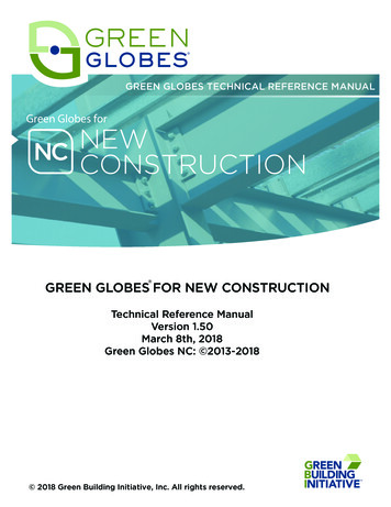
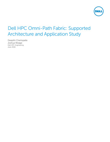
MSTPIEEE 802.1s Multiple Spanning Tree ProtocolNACNetwork Admission ControlOSPFOpen Shortest Path FirstPBBIEEE 802.1ah Provider Backbone BridgingQ-in-QIEEE 802.1ad Provider BridgingRADIUSRemote Access Dial-In User ServiceROIReturn on InvestmentRSTPIEEE 802.1w Rapid Spanning Tree ProtocolSAPService Access PointSDPService Distribution PointSPBIEEE 802.1aq Shortest Path BridgingSPB-MSPB MAC-in-MACSPB-VSPB Q-in-QSPFShortest Path FirstSTPIEEE 802.1D Spanning Tree ProtocolTLVType, Length, ValueUNPUser Network Profile1.4 References[1] IP/IPVPN services with IEEE 802.1aq SPB networks - draft-unbehagen-spb-ip-ipvpn-00.txt[2] Alcatel-Lucent OmniSwitch Template Based Provisioning with Alcatel-Lucent OmniVista 2500 Network Management System (NMS)[3] Network infrastructure security best practices2. The network needs to evolveLocal Area Networks (LAN) have traditionally relied on Spanning Tree Protocol (STP), and itsvariants (RSTP, MSTP), collectively referred to as “STP” for simplicity, for loop prevention. STPachieves a loop-free topology by electing a “root bridge” and building a least-cost tree linkingthe root bridge with other non-root nodes. This least-cost tree is created by pruning (disabling)all branches (links) which are not in the least-cost path towards the root. STP’s design principlepresents several drawbacks for modern Enterprise networks: Unused links: Creating a loop-free topology by disabling network links results in inefficientbandwidth use and low Return on Investment (ROI) Sub-optimal paths: While communication to-and-from the root bridge follows the leastcost path, communication between non-root bridges may need to traverse a sub-optimalroute transiting the root-bridge instead of alternative better routes over links that havebeen disabled Slow convergence: STP is a decades-old protocol designed when network devices were far lesspowerful than they are today. Even with the “rapid” version of STP, typical convergence timesare in the order of seconds. While STP re-converges to a new topology, transient loops mayform, resulting in packet drops, link saturation, and session timeouts.Tech BriefShortest Path Bridging Architecture guide5
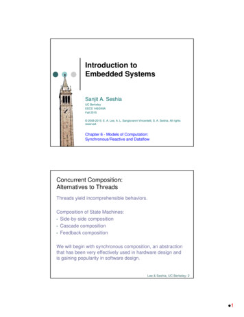
Figure 1. The problems with STPInefficientroutesDestination 2MACsM1 . M100SourceRoot bridgeAll the nodes onthe route need tolearn MAC’s M1-M100Cannot usethese linksDestination 1In addition to STP’s weaknesses, Ethernet’s scalability beyond the LAN is limited by its lack ofa coordinated control plane and use of a flat (as opposed to hierarchical) address space. LegacyEthernet networks present the following challenges: Flooding: Ethernet’s “flood and learn” address learning floods unknown-unicast traffic untilthe destination address is learned from return traffic MAC Learning: All nodes in the LAN learn all end-device MAC addresses thus posing ascalability challengeLastly, IEEE 802.1ad (Provider Bridging, or Q-in-Q) is limited to a maximum of 4096service instances.3. Introducing SPB802.1aq Shortest Path Bridging (SPB) is an IEEE networking standard whose primary focus wasaddressing the challenges in STP. But SPB is much more than STP’s evolution: SPB providesMPLS-like VPN services but is significantly simpler to deploy and maintain. And unlike MPLS,which requires a “stack” of protocols (for example: LDP, OSPF, MP-BGP, among others), SPB relieson a single protocol to provide this functionality: IS-IS (Intermediate System to IntermediateSystem). IS-IS is the only control plane protocol required to build a multi-path topology, performaddress learning, and carry VPN routes across the backbone. Alcatel-Lucent Enterprise’sIntelligent Fabric (iFab) brings further simplification by automating network node provisioning,client device attachment, and dynamic service instantiation. Because of this simplicity andautomation, an ALE-powered SPB solution offers high-end services for a lower total cost ofownership (TCO). Let’s analyse SPB’s benefits in further detail.Tech BriefShortest Path Bridging Architecture guide6
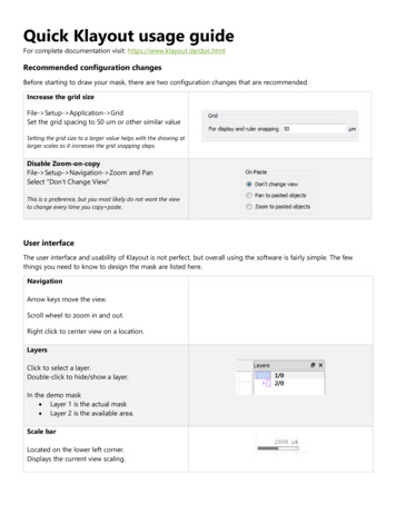
3.1 Scalable, fast-converging, multi-path fabricFigure 2. Addressing STP’s challenges1MultipleshortestpathsDestination 2PBBencapsulationat the edgesPBBencapsulationat the edges3MACsM1 . M1002All the linksare usableMACs M1-M100learning restrictedto the edgesPBBencapsulationat the edgesDestination 1SPB’s loop-free topology is built by a link-state routing protocol running Dijkstra’s ShortestPath First (SPF) algorithm: IS-IS. With IS-IS, no network link is disabled, all paths are availableand traffic between any pair of nodes follows the shortest path. In addition, with MAC-in-MACencapsulation, backbone nodes do not learn any end-device MAC addresses, thus increasingthe network scalability and stability. With IS-IS and MAC-in-MAC encapsulation, SPB creates an,any-to-any, scalable and fast-converging “fabric” supporting multiple active optimal paths forboth bridged and routed traffic.3.2 Multi-tenancySPB natively supports multi-tenancy: The physical network is partitioned into multiple virtual“slices” referred to as VPNs, “containers” or “communities”. Customers, or IoT device groups,segregated into different VPNs are isolated and do not interfere with one another. In fact, theycan use overlapping address space without conflict. Inter-VPN communication, if needed, istightly controlled by firewall policies. This multi-tenancy capability makes SPB suitable for usecases such as smart cities, transportation, higher education, video surveillance or data centres,to name a few. SPB’s scalability is not limited to 4096 tenants because its service identifier, theISID, is a 24-bit field which can differentiate up to 16M services.Figure 3. Multi-tenancyTech BriefShortest Path Bridging Architecture guide7
3.3 Dynamic service instantiationSPB services do not need to be statically bound to a switch port. SPB is tightly integrated withAlcatel-Lucent Enterprise’s classification and Network Admission Control (NAC) frameworkknown as Access Guardian (AG). Upon connection, end devices can be classified (for example;based on the MAC OUI or IoT “fingerprint” rules) or authenticated (for example; through 802.1xor MAC) against a RADIUS server. The appropriate service is dynamically instantiated accordingto the device or user classification, or role attribute returned by the RADIUS server. In the samemanner, this user-to-service binding is removed when the user/device disconnects. This dynamicservice instantiation has the following advantages: User/Device mobility: The network configuration dynamically adapts to mobile users anddevices or Virtual Machines (VMs) migrations without need for Move, Add or Change requests Increased security: Services are instantiated on an as-needed basis only, and for authenticateddevices/users only, if applicable. This association is maintained for as long as the user/deviceremains connected and/or authenticated, and is brought down on disconnection/log-off. Theseephemeral services are inherently more secure: they cannot be scanned, DoSd, or otherwisehacked, while they’re not active. Device templates: This dynamic instantiation of network services easily lends itself intotemplate-based configuration of network nodes. Edge nodes can all share the same baseconfiguration template and dynamically adjust the service configurations on the fly.3.4 Edge-only service provisioningWhether statically or dynamically instantiated, SPB services need only be provisioned on edgenodes, not on core nodes. Core nodes are effectively isolated from service Moves, Adds andChanges and require no touch while these activities are performed. In fact, service MACs canbe conducted during business hours and do not require a maintenance window to be scheduled,reducing time-to-service.3.5 Micro-segmentationFirewalls filter and control communication between different VPN “tenants” or “containers”.But, how do you secure communication within the same VPN? For instance, if one device werecompromised, how do you prevent lateral movement to other resources within the same VPN?When users/devices are dynamically bound to a service, they are also mapped to a User NetworkProfile (UNP). The UNP is a set of Access Control Lists (ACLs) and Quality of Service (QoS) policieswhich are applied to the device/user according to the device category or user role. Let’s takeCCTV cameras as an example: ACLs contained in the UNP can allow communication betweenthe camera and surveillance servers but at the same time block camera-to-camera communication,preventing the spread of malware, “pivoting” and other hacking techniques which rely onlateral movement.Tech BriefShortest Path Bridging Architecture guide8
Figure 4. Micro-segmentationAudio/visual profileAuthenticateClassifyAuto provision Container Quality SecurityCampus operation profileAuthenticateClassifyAuto provision Container Quality SecuritySecurity profileAuthenticateClassifyAuto provision Container Quality Security3.6 Non-IP coreEven when providing L3 services to IP packets, SPB core nodes do not route traffic, they bridgeit. In fact, SPB core nodes do not have IP addresses and the IS-IS control protocol, unlike OSPFand BGP, does not run on top of IP. This makes the network core inherently more secure andprotects it from IP-based attacks such as scanning, spoofing, DoS and others. Of course, SPBnodes still need an IP address for management purposes, but the management IP interface isisolated in its own service and VRF, not in-line with user traffic.4. The Data Plane: IEEE 802.1ah Provider backbone bridgingThe Data Plane’s (DP) mission is to forward user traffic between different ports. The DP makesno decisions as to what port a frame should be forwarded to. It simply performs lookups onthe Forwarding Data Base (FDB). FDB entries indicate what port, or group of ports, each frameshould be forwarded to and what encapsulation to use. Building, or populating entries in theFDB, is a function of the Control Plane (CP), which is discussed in the next section.The SPB data plane utilizes IEEE 802.1ah Provider Backbone Bridging (PBB), aka MAC-in-MAC,encapsulation. The PBB header includes de following fields:B-VID: Or Backbone VLAN (BVLAN) ID. A VLAN that serves as a transport VLAN for the SPBservice instances and to connect SPB bridges together through SPT sets. Unlike the standardVLAN domain which uses “flood and learn” or source learning in the DP to populate the FDB,the BVLAN domain’s FDB is pre-populated by the CP.ISID: Service Instance Identifier. The ISID is a 24-bit number that designates the service instance,tenant, container or VPN. Different SPB services are assigned different ISIDs and isolated fromone another. Each SPB service or ISID is bound to a BVLAN.B-SA and B-DA: Or Backbone source and destination MAC addresses. The MAC addresses associatedwith SPB nodes (BMACs). Within the SPB backbone, traffic is forwarded based on the destinationBMAC (B-DA). Inner customer MACs are not learnt or used for forwarding within the backbone.Tech BriefShortest Path Bridging Architecture guide9
Ethertype: 0x88E7Upon entering the SPB domain, the PBB header is wrapped around the incoming frame whichcan be un-tagged, single-tagged (IEEE 802.1q) or double-tagged (IEEE 802.1ad). Figure 5illustrates the case of a double-tagged (Q-in-Q) frame. Note that MAC and BMAC addressesare shortened to 2 bytes for simplicity in this diagram.Figure 5. PBB Data PlanePayloadEthertype (IP)C-VIDEthertype 802.1qS-VIDEthertype 802.1adPayloadEthertype (IP)Payload00:01PayloadEthertype (IP)00:02Ethertype (IP)C-VIDI-SIDC-VIDEthertype 802.1qEthertype 802.1ahEthertype 802.1qPayloadEthertype (IP)C-VIDS-VIDB-VIDS-VIDC-VIDEthertype 802.1qEthertype 802.1adEthertype 802.1adEthertype 802.1adEthertype 200:02MAC :00:01MAC :00:0ACustomernetworkProvider bridgenetworkMAC :00:02MAC :00:0BProvider backbonebridge networkProvider bridgenetworkCustomernetworkLet’s define a few key terms.BEB: An SPB switch positioned at the edge of the PBB network that learns and encapsulates(adds an 802.1ah backbone header to) “customer” frames for transport across the backbonenetwork. The BEB interconnects the customer network space with PBB network space.BCB: An SPB node that resides inside the PBB network core. The BCB employs the same BVLANon two or more network ports. This BVLAN does not terminate on the switch itself; trafficreceived on an SPB network port is switched to other SPB network ports. As a result, the BCBdoes not have to learn any of the customer MAC addresses. It mainly serves as a transit bridgefor the PBB network.Within the SPB domain, that is, between BEB and BCB nodes, frame forwarding depends entirelyon the outer PBB 802.1ah header (BMAC and BVLAN) and not on the inner header or “customer”MAC addresses (CMAC). In fact, the SPB backbone nodes do not learn CMACs and this makesSPB networks more scalable and stable (CMACs are not learnt and therefore do not need to beflushed and re-learnt when they change or move).The DP implements an additional loop mitigation mechanism by which a node will not acceptunexpected frames from their neighbours. This additional loop mitigation mechanism is fasterduring topology changes. In summary, SPB implements two loop avoidance mechanisms: loopprevention and loop mitigation.Tech BriefShortest Path Bridging Architecture guide10
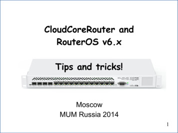
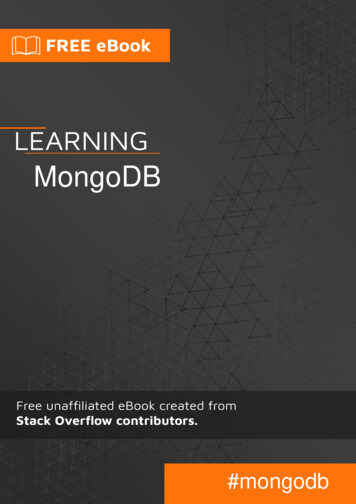
5. The Control Plane: RFC 6329 IS-IS Equal-cost treesAs stated earlier, the role of the CP is to populate the FDB tables used by the DP. SPB uses IS-IS,or Intermediate System to Intermediate System (ISO/IEC 10589:2002); a well-known, provenand widely-deployed protocol, particularly in service-provider backbones. IS-IS is responsiblefor topology and service discovery. IS-IS is an extensible link-state protocol which implementsDijkstra’s Shortest Path algorithm for path computation. IS-IS extensions for SPB are describedin RFC 6329 and include a new Network Layer Protocol Identifier (NLPID), as well as a set ofType-Length-Values (TLVs). In a nutshell, these extensions add support for multiple topologies,allowing load sharing over multiple equal-cost paths, and service-membership discovery, or inother words: Communicating what services are enabled on each SPB node.Figure 6. RFC 6329 IS-IS extensionsNew!SPB extensionsNLPI, TLVs, PDUsExisting!Discovery and computationDiscovery – Hello and LSP packets, Computation – SPF and SPTSPB-ISISUnlike STP which creates a single tree rooted at the root bridge, in SPB networks, every nodebuilds a topology tree rooted on itself. This is the key reason why, in an SPB network, trafficbetween any pair of nodes always travels along the shortest path. When using STP, trafficbetween two nodes does not necessarily travel over the shortest path unless one of the twonodes involved is the root bridge. This is illustrated in figure 7 in which B1 is the root bridge.Traffic between nodes B5 and B2 for instance, none of which is the root bridge, cannot use thedirect single-hop path because that link is disabled by STP. Traffic between these two nodesmust take a 3-hop detour traversing the root bridge.Figure 7. Multiple treesSpanning TreeSingle root bridgeSPBEvery bridge is the rootB2B2B1B5B3B5B1B3B4B4Path B5 to B2 B5 – B3 – B1 – B2Path B5 to B2 B5 – B2In contrast, when using SPB, no link is disabled: each node is the root of its own tree. Nodes B2and B5 can simply communicate over the direct single-hop path while at the same time they cancommunicate with other nodes over different paths (for example; between B4 and B5). SPB’ssupport for multiple trees and multiple active paths unlocks utilization of bandwidth in optimalpaths that would otherwise be wasted, increasing throughput and reducing latency.An SPB network supports up to 16 BVLANs and each node builds a SPF tree for each BVLAN.Load balancing is accomplished by mapping different tenant services (ISIDs) to different BVLANs.Service traffic between any node pair uses a single path and this path only changes if thetopology changes, for instance, on node or link failure and subsequent path re-computation. Inother words: SPB networks do not balance loads on a packet-by-packet basis like IP networksdo. Provided the physical topology supports multiple shortest paths (same cost and same hopTech BriefShortest Path Bridging Architecture guide11
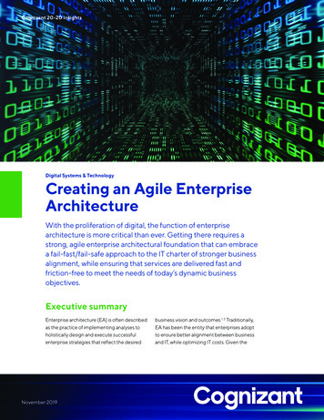
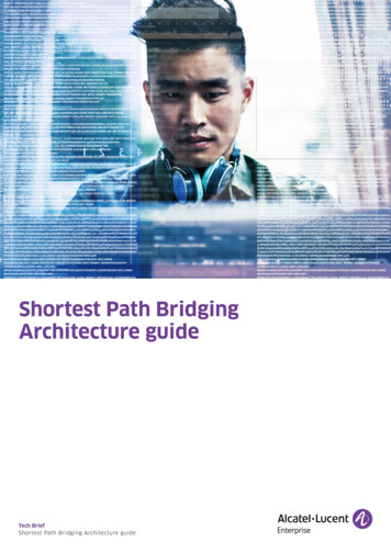
count) between two nodes, different BVLANs can build different trees and services mapped tothose BVLANs can use different paths. And, those paths will remain the same for as long as thetopology remains the same. An important property of SPB networks is that network paths aredeterministic and frames are delivered in the order they were sent. This property is importantfor certain applications such as storage and real-time application traffic.Figure 8. One tree per node and per BVLANB1’s tree on BVLAN AB2B1B1B3B1’s tree on BVLAN BB2B5B1B3B1’s tree on BVLAN CB2B5B1B3B4B4B4B5’s tree on BVLAN AB2B5’s tree on BVLAN BB2B5’s tree on BVLAN CB2B3B5B1B4B3B4B5B1B3B5B5B4The trees shown in figure 8 are SPB’s equal-cost trees (ECTs). Each node builds a tree perBVLAN and the cost to reach other nodes is the same across all BVLANs. The ECT-ID is a numberassigned to each BVLAN at the time of BVLAN creation and is used for tie breaking during pathcomputation. Assigning different ECT-IDs to different BVLANs helps those BVLANs build differenttrees, provided the underlying topology supports multiple equal-cost, or shortest paths.Another important property of SPB networks is path symmetry. If you closely examine thepicture above, you will notice that the path from node X to node Y is identical to the path fromnode Y to node X. Path symmetry is key to Operations and Maintenance (OAM). For instance,one-way delay calculations can be easily derived from roundtrip delay measurements. Notethat this is not the case for other IP-based technologies such as MPLS in which the reversepath may differ.Tech BriefShortest Path Bridging Architecture guide12
Figure 9. Symmetric paths, per-BVLAN load balancingB1 – B5 path BVLAN AB1 – B5 path BVLAN BB1 – B5 path BVLAN CB2B2B2B3B1B5B1B4B3B5B1B3B5B4B4The result of IS-IS path computation for each BVLAN and node is the FDB which is used by thedata plane for frame forwarding. Figure 10 shows BEB5’s unicast FDB. The multicast FDB willbe discussed in Section 7.Figure 10. B5’s Unicast FDBB2B3B1B5B4BVIDNodeOutbound portBVID AB1Port 1BVID BB1Port 2BVID CB1Port 3BVID AB2Port 1BVID BB2Port 1BVID CB2Port 1BVID AB3Port 2BVID BB3Port 2BVID CB3Port 2BVID AB4Port 3BVID BB4Port 3BVID CB4Port 36. The service frameworkAn SPB service represents a VPN, or tenant, and is uniquely identified by its service identifier,the ISID. An SPB service needs only be created, or instantiated, on BEB nodes, not on BCBnodes, and only on those BEB nodes servicing locations associated to the service. SPB servicemembership information is shared across the SPB backbone by way of IS-IS TLVs such that allSPB nodes have a consistent view of the services which are active on each BEB. Each nodethen builds a service database.Figure 11. The service databaseISID 66B2B1B5B3ISID 66ISID 66ISID 77ISID 77ISIDBVIDNode66BVID AB166BVID AB266BVID AB466BVID AB577BVID BB177BVID BB5B4ISID 66Tech BriefShortest Path Bridging Architecture guide13
In each BEB node there are two kinds of virtual ports:Service Access Point: The SAP is a UNI-side logical port which binds a physical port and specificcustomer traffic types (untagged, single-tagged, double-tagged or all) to an SPB service. MultipleSAPs can be associated to the same physical port thus multiplexing and mapping differentcustomer traffic encapsulations to different SPB services.Service Distribution Point: The SDP is an NNI-side logical port which binds an SPB service toa far-end BEB on which the service is instantiated. SDPs are dynamically created in the CP andonly for those far-end BEBs with SAPs for the specific service.Let’s look at figure 12. In this diagram, B5 terminates 2 SPB services: One is associated toISID 66 and the other to ISID 77. There are two SAP ports, one for each service. SAP 1:1 isdefined on port 1, matches traffic tagged with VLAN 1, and binds it to service 66. SAP 2:2is defined on port 2, matches traffic tagged with VLAN 2, and binds it to ISID 77.ISID 66 is also enabled on nodes B1, B2 and B4 while ISID 77 is also enabled on node B1.Figure 12. The service frameworkISID 66IdentifierBVIDNodeB2SAP 1:1——SAP 2:2——SDP 32769: 66BVID AB1SDP 32768: 66BVID AB2SDP 32767: 66BVID AB4SDP 32766: 77BVID BB1SDPY:66B1B5SAP 1:1SDP X:77SAP 2:2Z:66SDP X:66SDPISID 66ISID 77ISID 66ISID 77B4ISID 66It should be noted that while BMAC address learning is performed in the CP (for example; notthrough “flood and learn”) CMAC address learning is performed in the BEB’s DP through floodand learn. Near-end CMACs are bound to SAP ports and far-end CMACs are bound to SDP ports.BCB nodes have neither SAP nor SDP ports and therefore do not learn any CMACs.Let’s expand this example by adding some end customer sites and CMACs associated to thosecustomers. We will keep using 2-byte MAC addresses for simplicity. In figure 13, near-end CMACaddresses are bound to SAP ports while far-end CMAC addresses are bound to SDP ports. Withinthe service domain, a BEB performs CMAC source address learning like a standard Ethernetswitch, except there is no “flooding” of BUM traffic. BUM traffic is discussed in the next section.Figure 13. Customer MAC address learningISID 66B2MAC C:CMAC B:BSDPMAC A:AY:66B1B5SDP 1:1SDP X:77SDP 2:2ISIDCMACSAP 1:166A:AE:ESAP 2:277SDP 32769: 6666C:CSDP 32768: 6666B:BSDP 32767: 6666D:DSDP 32766: 7777G:GPISID 66SDMAC G:GZ:66SDP X:66IdentifierISID 77ISID 66ISID 77MAC E:EB4ISID 66MAC D:DTech BriefShortest Path Bridging Architecture guide14
7. BUM trafficSPB supports 3 BUM (broadcast, unknown unicast, and multicast) traffic replication andforwarding methods:Head-end: In this mode, BUM traffic received on a SAP port is replicated at the ingress BEB andconverted to multiple unicast frames: A replica is created for every other BEB in the same ISIDand these replicas have the BEB BMACs as the B-DA and are forwarded using the unicast FDB.For this reason, Head-End replication can be inefficient in terms of bandwidth consumption butis efficient in terms of resource usage because it does not require a separate tree. However,Head-end replication can be optimal in some circumstances, particularly
STP IEEE 802.1D Spanning Tree Protocol TLV Type, Length, Value UNP User Network Profile 1.4 References [1] IP/IPVPN services with IEEE 802.1aq SPB networks - draft-unbehagen-spb-ip-ipvpn-00.txt [2] Alcatel-Lucent OmniSwitch Template Based Provisioning with Alcat