Transcription
Department of EnergyFundamentals HandbookMECHANICAL SCIENCEModule 4Valves
k & Wilcox, Steam, Its Generation and Use, Babcock & Wilcox Co., 1978.Cheremisinoff, N. P., Fluid Flow, Pumps, Pipes and Channels, Ann Arbor Science.Heat Transfer, Thermodynamics and Fluid Flow Fundamentals, Columbia, MD, GeneralPhysics Corporation, Library of Congress Card #A 326517, 1982.Schweitzer, Philip A., Handbook of Valves, Industrial Press Inc.Stewart, Harry L., Pneumatics & Hydraulics, Theodore Audel & Company, 1984.ME-04Page viRev. 0
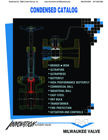
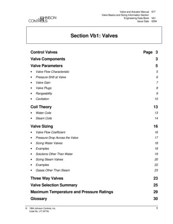
ValvesDOE-HDBK-1018/2-93VALVE FUNCTIONS AND BASIC PARTSVALVE FUNCTIONS AND BASIC PARTSValves are the most common single piece of equipment found in DOE facilities.Although there are many types, shapes, and sizes of valves, they all have thesame basic parts. This chapter will review the common parts and functions of avalve.EO 1.1DESCRIBE the four basic types of flow control elementsem ployed in valve design.EO 1.2DESCRIBE how valve stem leakage is controlled.EO 1.3Given a drawing of a valve, IDENTIFY the following:a.b.c.d.B odyB A valve is a mechanical device that controls the flow of fluid and pressure within a system orprocess. A valve controls system or process fluid flow and pressure by performing any of thefollowing functions:Stopping and starting fluid flowVarying (throttling) the amount of fluid flowControlling the direction of fluid flowRegulating downstream system or process pressureRelieving component or piping over pressureThere are many valve designs and types that satisfy one or more of the functions identifiedabove. A multitude of valve types and designs safely accommodate a wide variety of industrialapplications.Regardless of type, all valves have the following basic parts: the body, bonnet, trim (internalelements), actuator, and packing. The basic parts of a valve are illustrated in Figure 1.Rev. 0Page 1ME-04
VALVE FUNCTIONS AND BASIC PARTSDOE-HDBK-1018/2-93ValvesValve BodyThe body, sometimes called the shell, is the primary pressure boundary of a valve. It serves asthe principal element of a valve assembly because it is the framework that holds everythingtogether.The body, the first pressure boundary of a valve, resists fluid pressure loads from connectingpiping. It receives inlet and outlet piping through threaded, bolted, or welded joints.Valve bodies are cast or forged into avariety of shapes. Although a sphereor a cylinder would theoretically bethe most economical shape to resistfluid pressure when a valve is open,there are many other considerations.For example, many valves require apartition across the valve body tosupport the seat opening, which is thethrottling orifice. With the valveclosed, loading on the body isdifficult to determine. The valve endconnections also distort loads on asimple sphere and more complicatedshapes.Ease of manufacture,assembly, and costs are additionalimportant considerations. Hence, thebasic form of a valve body typicallyis not spherical, but ranges fromsimple block shapes to highlycomplex shapes in which the bonnet,a removable piece to make assemblypossible, forms part of the pressureresisting body.Narrowing of the fluid passage(venturi effect) is also a commonmethod for reducing the overall sizeand cost of a valve.In otherinstances, large ends are added to thevalve for connection into a largerline.ME-04Figure 1 Basic Parts of a ValvePage 2Rev. 0
ValvesDOE-HDBK-1018/2-93VALVE FUNCTIONS AND BASIC PARTSValve BonnetThe cover for the opening in the valve body is the bonnet. In some designs, the body itself issplit into two sections that bolt together. Like valve bodies, bonnets vary in design. Somebonnets function simply as valve covers, while others support valve internals and accessoriessuch as the stem, disk, and actuator.The bonnet is the second principal pressure boundary of a valve. It is cast or forged of the samematerial as the body and is connected to the body by a threaded, bolted, or welded joint. In allcases, the attachment of the bonnet to the body is considered a pressure boundary. This meansthat the weld joint or bolts that connect the bonnet to the body are pressure-retaining parts.Valve bonnets, although a necessity for most valves, represent a cause for concern. Bonnets cancomplicate the manufacture of valves, increase valve size, represent a significant cost portionof valve cost, and are a source for potential leakage.Valve TrimThe internal elements of a valve are collectively referred to as a valve's trim . The trim typicallyincludes a disk, seat, stem, and sleeves needed to guide the stem. A valve's performance isdetermined by the disk and seat interface and the relation of the disk position to the seat.Because of the trim, basic motions and flow control are possible. In rotational motion trimdesigns, the disk slides closely past the seat to produce a change in flow opening. In linearmotion trim designs, the disk lifts perpendicularly away from the seat so that an annular orificeappears.Disk and SeatFor a valve having a bonnet, the disk is the third primary principal pressure boundary.The disk provides the capability for permitting and prohibiting fluid flow. With the diskclosed, full system pressure is applied across the disk if the outlet side is depressurized.For this reason, the disk is a pressure-retaining part. Disks are typically forged and, insome designs, hard-surfaced to provide good wear characteristics. A fine surface finishof the seating area of a disk is necessary for good sealing when the valve is closed. Mostvalves are named, in part, according to the design of their disks.The seat or seal rings provide the seating surface for the disk. In some designs, the bodyis machined to serve as the seating surface and seal rings are not used. In other designs,forged seal rings are threaded or welded to the body to provide the seating surface. Toimprove the wear-resistance of the seal rings, the surface is often hard-faced by weldingand then machining the contact surface of the seal ring. A fine surface finish of theseating area is necessary for good sealing when the valve is closed. Seal rings are notusually considered pressure boundary parts because the body has sufficient wall thicknessto withstand design pressure without relying upon the thickness of the seal rings.Rev. 0Page 3ME-04
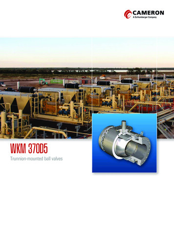
VALVE FUNCTIONS AND BASIC PARTSDOE-HDBK-1018/2-93ValvesStemThe stem , which connects the actuator and disk, is responsible for positioning the disk.Stems are typically forged and connected to the disk by threaded or welded joints. Forvalve designs requiring stem packing or sealing to prevent leakage, a fine surface finishof the stem in the area of the seal is necessary. Typically, a stem is not considered apressure boundary part.Connection of the disk to the stem can allow some rocking or rotation to ease thepositioning of the disk on the seat. Alternately, the stem may be flexible enough to letthe disk position itself against the seat. However, constant fluttering or rotation of aflexible or loosely connected disk can destroy the disk or its connection to the stem.Two types of valve stems are rising stems and nonrising stems. Illustrated in Figures 2and 3, these two types of stems are easily distinguished by observation. For a rising stemvalve, the stem will rise above the actuator as the valve is opened. This occurs becausethe stem is threaded and mated with the bushing threads of a yoke that is an integral partof, or is mounted to, the bonnet.Figure 2 Rising StemsME-04Page 4Rev. 0
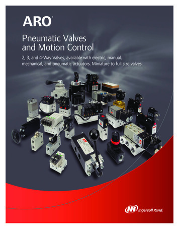
ValvesDOE-HDBK-1018/2-93VALVE FUNCTIONS AND BASIC PARTSFigure 3 Nonrising StemsThere is no upward stem movement from outside the valve for a nonrising stem design.For the nonrising stem design, the valve disk is threaded internally and mates with thestem threads.Valve ActuatorThe actuator operates the stem and disk assembly. An actuator may be a manually operatedhandwheel, manual lever, motor operator, solenoid operator, pneumatic operator, or hydraulicram. In some designs, the actuator is supported by the bonnet. In other designs, a yokemounted to the bonnet supports the actuator.Except for certain hydraulically controlled valves, actuators are outside of the pressure boundary.Yokes, when used, are always outside of the pressure boundary.Valve PackingMost valves use some form of packing to prevent leakage from the space between the stem andthe bonnet. Packing is commonly a fibrous material (such as flax) or another compound (suchas teflon) that forms a seal between the internal parts of a valve and the outside where the stemextends through the body.Valve packing must be properly compressed to prevent fluid loss and damage to the valve'sstem. If a valve's packing is too loose, the valve will leak, which is a safety hazard. If thepacking is too tight, it will impair the movement and possibly damage the stem.Rev. 0Page 5ME-04
VALVE FUNCTIONS AND BASIC PARTSDOE-HDBK-1018/2-93ValvesIntroduction to the Types of ValvesBecause of the diversity of the types of systems, fluids, and environments in which valves mustoperate, a vast array of valve types have been developed. Examples of the common types arethe globe valve, gate valve, ball valve, plug valve, butterfly valve, diaphragm valve, check valve,pinch valve, and safety valve. Each type of valve has been designed to meet specific needs.Some valves are capable of throttling flow, other valve types can only stop flow, others workwell in corrosive systems, and others handle high pressure fluids. Each valve type has certaininherent advantages and disadvantages. Understanding these differences and how they effect thevalve's application or operation is necessary for the successful operation of a facility.Although all valves have the same basic components and function to control flow in somefashion, the method of controlling the flow can vary dramatically. In general, there are fourmethods of controlling flow through a valve.1.Move a disc, or plug into or against an orifice (for example, globe or needle typevalve).2.Slide a flat, cylindrical, or spherical surface across an orifice (for example, gateand plug valves).3.Rotate a disc or ellipse about a shaft extending across the diameter of an orifice(for example, a butterfly or ball valve).4.Move a flexible material into the flow passage (for example, diaphragm and pinchvalves).Each method of controlling flow has characteristics that makes it the best choice for a givenapplication of function.ME-04Page 6Rev. 0
ValvesDOE-HDBK-1018/2-93VALVE FUNCTIONS AND BASIC PARTSSummaryThe following important information in this chapter is summarized below:Valve Functions and Basic Parts SummaryThere are four basic types of flow control elements employed in valve design.1.Move a disc, or plug into or against an orifice (for example, globe orneedle type valve).2.Slide a flat, cylindrical, or spherical surface across an orifice (for example,gate and plug valves).3.Rotate a disc or ellipse about a shaft extending across the diameter of anorifice (for example, a butterfly or ball valve).4.Move a flexible material into the flow passage (for example, diaphragmand pinch valves).Valve stem leakage is usually controlled by properly compressing the packingaround the valve stem.There are seven basic parts common to most valves.Rev. 0Page 7ME-04
TYPES OF VALVESDOE-HDBK-1018/2-93ValvesT YPES OF VALVE SDue to the various environments, system fluids, and system conditions in whichflow must be controlled, a large number of valve designs have been developed.A basic understanding of the differences between the various types of valves, andhow these differences affect valve function, will help ensure the proper applicationof each valve type during design and the proper use of each valve type duringoperation.EO 1.4Given a drawing of a valve, IDENTIFY each of the followingtypes of valves:a.b.c.d.e.f.EO 1.5GlobeGatePlugB ety/reliefReducingDESCRIBE the application of the following types of valves:a.b.c.d.e.f.GlobeGatePlugB ety/reliefReducingGate ValvesA gate valve is a linear motion valve used to start or stop fluid flow; however, it does notregulate or throttle flow. The name gate is derived from the appearance of the disk in the flowstream. Figure 4 illustrates a gate valve.The disk of a gate valve is completely removed from the flow stream when the valve is fullyopen. This characteristic offers virtually no resistance to flow when the valve is open. Hence,there is little pressure drop across an open gate valve.When the valve is fully closed, a disk-to-seal ring contact surface exists for 360 , and goodsealing is provided. With the proper mating of a disk to the seal ring, very little or no leakageoccurs across the disk when the gate valve is closed.ME-04Page 8Rev. 0
ValvesDOE-HDBK-1018/2-93TYPES OF VALVESFigure 4 Gate ValveRev. 0Page 9ME-04
TYPES OF VALVESDOE-HDBK-1018/2-93ValvesOn opening the gate valve, the flow path is enlarged in a highly nonlinear manner with respectto percent of opening. This means that flow rate does not change evenly with stem travel.Also, a partially open gate disk tends to vibrate from the fluid flow. Most of the flow changeoccurs near shutoff with a relatively high fluid velocity causing disk and seat wear and eventualleakage if used to regulate flow. For these reasons, gate valves are not used to regulate orthrottle flow.A gate valve can be used for a wide variety of fluids and provides a tight seal when closed. Themajor disadvantages to the use of a gate valve are:It is not suitable for throttling applications.It is prone to vibration in the partially open state.It is more subject to seat and disk wear than a globe valve.Repairs, such as lapping and grinding, are generally more difficult to accomplish.Gate Valve Disk DesignGate valves are available with a variety of disks. Classification of gate valves is usually madeby the type disk used: solid wedge, flexible wedge, split wedge, or parallel disk.Solid wedges, flexible wedges, and split wedges are used in valves having inclined seats. Paralleldisks are used in valves having parallel seats.Regardless of the style of wedge or disk used, the disk is usually replaceable. In services wheresolids or high velocity may cause rapid erosion of the seat or disk, these components shouldhave a high surface hardness and should have replacement seats as well as disks. If the seatsare not replaceable, seat damage requires removal of the valve from the line for refacing of theseat, or refacing of the seat in place. Valves being used in corrosion service should normallybe specified with replaceable seats.ME-04Page 10Rev. 0
ValvesDOE-HDBK-1018/2-93TYPES OF VALVESSolid WedgeThe solid wedge gate valve shown in Figure 5 is the mostcommonly used disk because of its simplicity and strength.A valve with this type of wedge may be installed in anyposition and it is suitable for almost all fluids. It is practicalfor turbulent flow.Flexible WedgeThe flexible wedge gate valve illustrated in Figure 6 is aone-piece disk with a cut around the perimeter to improvethe ability to match error or change in the angle between theseats. The cut varies in size, shape, and depth. A shallow,narrow cut gives little flexibility but retains strength. Adeeper and wider cut, or cast-in recess, leaves little materialat the center, which allows more flexibility but compromisesstrength.A correct profile of the disk half in theflexible wedge design can give uniformFigure 5deflection properties at the disk edge,SolidWedgeGate Valveso that the wedging force applied inseating will force the disk seatingsurface uniformly and tightly against the seat.Gate valves used in steam systems have flexible wedges. Thereason for using a flexible gate is to prevent binding of the gatewithin the valve when the valve is in the closed position. Whensteam lines are heated, they expand and cause some distortion ofvalve bodies. If a solid gate fits snugly between the seat of a valvein a cold steam system, when the system is heated and pipeselongate, the seats will compress against the gate and clamp thevalve shut. This problem is overcome by using a flexible gate,whose design allows the gate to flex as the valve seat compresses it.Figure 6Flexible Wedge Gate ValveRev. 0The major problem associated with flexible gates is that water tendsto collect in the body neck. Under certain conditions, the admissionof steam may cause the valve body neck to rupture, the bonnet to liftoff, or the seat ring to collapse. Following correct warmingprocedures prevent these problems.Page 11ME-04
TYPES OF VALVESDOE-HDBK-1018/2-93ValvesSplit WedgeSplit wedge gate valves, as shown in Figure 7, are of theball and socket design. These are self-adjusting and selfaligning to both seating surfaces. The disk is free toadjust itself to the seating surface if one-half of the diskis slightly out of alignment because of foreign matterlodged between the disk half and the seat ring. Thistype of wedge is suitable for handling noncondensinggases and liquids at normal temperatures, particularlycorrosive liquids. Freedom of movement of the disk inthe carrier prevents binding even though the valve mayhave been closed when hot and later contracted due tocooling. This type of valve should be installed with thestem in the vertical position.Parallel DiskThe parallel disk gate valve illustrated in Figure 8 isdesigned to prevent valve binding due to thermaltransients. This design is used in both low and highpressure applications.Figure 7 Split Wedge Gate ValveThe wedge surfaces between the parallel face disk halves are caused to press togetherunder stem thrust and spread apart the disks to seal against the seats. The taperedwedges may be part of the disk halves or they may be separate elements. The lowerwedge may bottom out on a rib at the valve bottom so that the stem can develop seatingforce. In one version, the wedge contact surfaces are curved to keep the point of contactclose to the optimum.In other parallel disk gates, the two halves do not move apart under wedge action.Instead, the upstream pressure holds the downstream disk against the seat. A carrier ringlifts the disks, and a spring or springs hold the disks apart and seated when there is noupstream pressure.Another parallel gate disk design provides for sealing only one port. In these designs,the high pressure side pushes the disk open (relieving the disk) on the high pressure side,but forces the disk closed on the low pressure side. With such designs, the amount ofseat leakage tends to decrease as differential pressure across the seat increases. Thesevalves will usually have a flow direction marking which will show which side is the highpressure (relieving) side. Care should be taken to ensure that these valves are notinstalled backwards in the system.ME-04Page 12Rev. 0
ValvesDOE-HDBK-1018/2-93TYPES OF VALVESFigure 8 Parallel Disk Gate ValveSome parallel disk gate valves used in high pressure systems are made with an integralbonnet vent and bypass line. A three-way valve is used to position the line to bypass inorder to equalize pressure across the disks prior to opening. When the gate valve isclosed, the three-way valve is positioned to vent the bonnet to one side or the other.This prevents moisture from accumulating in the bonnet. The three-way valve ispositioned to the high pressure side of the gate valve when closed to ensure that flowdoes not bypass the isolation valve. The high pressure acts against spring compressionand forces one gate off of its seat. The three-way valve vents this flow back to thepressure source.Rev. 0Page 13ME-04
TYPES OF VALVESDOE-HDBK-1018/2-93ValvesGate Valve Stem DesignGate valves are classified as either rising stem or nonrising stem valves. For the nonrising stemgate valve, the stem is threaded on the lower end into the gate. As the hand wheel on the stemis rotated, the gate travels up or down the stem on the threads while the stem remains verticallystationary. This type valve will almost always have a pointer-type indicator threaded onto theupper end of the stem to indicate valve position. Figures 2 and 3 illustrate rising-stem gatevalves and nonrising stem gate valves.The nonrising stem configuration places the stem threads within the boundary established by thevalve packing out of contact with the environment. This configuration assures that the stemmerely rotates in the packing without much danger of carrying dirt into the packing from outsideto inside.Rising stem gate valves are designed so that the stem is raised out of the flowpath when thevalve is open. Rising stem gate valves come in two basic designs. Some have a stem that risesthrough the handwheel while others have a stem that is threaded to the bonnet.Gate Valve Seat DesignSeats for gate valves are either provided integral with the valve body or in a seat ring type ofconstruction. Seat ring construction provides seats which are either threaded into position or arepressed into position and seal welded to the valve body. The latter form of construction isrecommended for higher temperature service.Integral seats provide a seat of the same material of construction as the valve body while thepressed-in or threaded-in seats permit variation. Rings with hard facings may be supplied forthe application where they are required.Small, forged steel, gate valves may have hard faced seats pressed into the body. In someseries, this type of valve in sizes from 1/2 to 2 inches is rated for 2500 psig steam service. Inlarge gate valves, disks are often of the solid wedge type with seat rings threaded in, welded in,or pressed in. Screwed in seat rings are considered replaceable since they may be removed andnew seat rings installed.ME-04Page 14Rev. 0
ValvesDOE-HDBK-1018/2-93TYPES OF VALVESGlobe ValvesA globe valve is a linear motion valveused to stop, start, and regulate fluid flow.A Z-body globe valve is illustrated inFigure 9.As shown in Figure 9, the globe valvedisk can be totally removed from theflowpath or it can completely close theflowpath. The essential principle of globevalve operation is the perpendicularmovement of the disk away from the seat.This causes the annular space between thedisk and seat ring to gradually close as thevalve is closed. This characteristic givesthe globe valve good throttling ability,which permits its use in regulating flow.Therefore, the globe valve may be usedfor both stopping and starting fluid flowand for regulating flow.When compared to a gate valve, a globevalve generally yields much less seatleakage. This is because the disk-to-seatring contact is more at right angles, whichpermits the force of closing to tightly seatthe disk.Figure 9 Z-Body Globe ValveGlobe valves can be arranged so that the disk closes against or in the same direction of fluidflow. When the disk closes against the direction of flow, the kinetic energy of the fluid impedesclosing but aids opening of the valve. When the disk closes in the same direction of flow, thekinetic energy of the fluid aids closing but impedes opening. This characteristic is preferableto other designs when quick-acting stop valves are necessary.Globe valves also have drawbacks. The most evident shortcoming of the simple globe valve isthe high head loss from two or more right angle turns of flowing fluid. Obstructions anddiscontinuities in the flowpath lead to head loss. In a large high pressure line, the fluid dynamiceffects from pulsations, impacts, and pressure drops can damage trim, stem packing, andactuators. In addition, large valve sizes require considerable power to operate and are especiallynoisy in high pressure applications.Other drawbacks of globe valves are the large openings necessary for disk assembly, heavierweight than other valves of the same flow rating, and the cantilevered mounting of the disk tothe stem.Rev. 0Page 15ME-04
TYPES OF VALVESDOE-HDBK-1018/2-93ValvesGlobe Valve Body DesignsThe three primary body designs for globe valves are Z-body, Y-body, and Angle.Z-Body DesignThe simplest design and most common for water applications is the Z-body. The Z-bodyis illustrated in Figure 9. For this body design, the Z-shaped diaphragm or partitionacross the globular body contains the seat. The horizontal setting of the seat allows thestem and disk to travel at right angles to the pipe axis. The stem passes through thebonnet which is attached to a large opening at the top of the valve body. This providesa symmetrical form that simplifies manufacture, installation, and repair.Y-Body DesignFigure 10 illustrates a typicalY-body globe valve. Thisdesign is a remedy for the highpressure drop inherent in globevalves. The seat and stem areangled at approximately 45 .The angle yields a straighterflowpath (at full opening) andprovides the stem, bonnet, andpacking a relatively pressureresistant envelope.Figure 10 Y-Body Globe ValveME-04Page 16Y-body globe valves are bestsuited for high pressure andother severe services. In smallsizes for intermittent flows,the pressure loss may not be asimportant as the otherconsiderations favoring theY-body design. Hence, theflow passage of small Y-bodyglobe valves is not as carefullystreamlined as that for largervalves.Rev. 0
ValvesDOE-HDBK-1018/2-93TYPES OF VALVESAngle Valve DesignThe angle body globe valve design, illustratedin Figure 11, is a simple modification of thebasic globe valve. Having ends at rightangles, the diaphragm can be a simple flatplate. Fluid is able to flow through with onlya single 90 turn and discharge downwardmore symmetrically than the discharge froman ordinary globe. A particular advantage ofthe angle body design is that it can functionas both a valve and a piping elbow.For moderate conditions of pressure,temperature, and flow, the angle valve closelyresembles the ordinary globe. The anglevalve's discharge conditions are favorablewith respect to fluid dynamics and erosion.Globe Valve DisksFigure 11 Angle Globe ValveMost globe valves use one of three basic diskdesigns: the ball disk, the composition disk,and the plug disk.Ball DiskThe ball disk fits on a tapered, flat-surfaced seat. The ball disk design is used primarilyin relatively low pressure and low temperature systems. It is capable of throttling flow,but is primarily used to stop and start flow.Composition DiskThe composition disk design uses a hard, nonmetallic insert ring on the disk. The insertring creates a tighter closure. Composition disks are primarily used in steam and hotwater applications. They resist erosion and are sufficiently resilient to close on solidparticles without damaging the valve. Composition disks are replaceable.Plug DiskBecause of its configuration, the plug disk provides better throttling than ball orcomposition designs. Plug disks are available in a variety of specific configurations. Ingeneral, they are all long and tapered.Rev. 0Page 17ME-04
TYPES OF VALVESDOE-HDBK-1018/2-93ValvesGlobe Valve Disk and Stem ConnectionsGlobe valves employ two methods for connecting disk and stem: T-slot construction and disknut construction. In the T-slot design, the disk slips over the stem. In the disk nut design, thedisk is screwed into the stem.Globe Valve SeatsGlobe valve seats are either integral with or screwed into the valve body. Many globe valveshave backseats. A backseat is a seating arrangement that provides a seal between the stem andbonnet. When the valve is fully open, the disk seats against the backseat. The backseat designprevents system pressure from building against the valve packing.Globe Valve Direction of FlowFor low temperature applications, globe and angle valves are ordinarily installed so that pressureis under the disk. This promotes easy operation, helps protect the packing, and eliminates acertain amount of erosive action to the seat and disk faces. For high temperature steam service,globe valves are installed so that pressure is above the disk. Otherwise, the stem will contractupon cooling and tend to lift the disk off the seat.Ball ValvesA ball valve is a rotational motion valve that uses a ball-shaped disk to stop or start fluid flow.The ball, shown in Figure 12, performs the same function as the disk in the globe valve. Whenthe valve handle is turned to open the valve, the ball rotates to a point where the hole throughthe ball is in line with the valve body inlet and outlet. When the valve is shut, the ball is rotatedso that the hole is perpendicular to the flow openings of the valve body and the flow is stopped.Most ball valve actuators are of the quick-acting type, which require a 90 turn of the valvehandle to operate the valve. Other ball valve actuators are planetary gear-operated. This typeof gearing allows the use of a relatively small handwheel and operating force to operate a fairlylarge valve.Some ball valves have been developed with a spherical surface coated plug that is off to one sidein the open position and rotates into the flow passage until it blocks the flowpath completely.Seating is accomplished by the eccentric movement of the plug. The valve requires nolubrication and can be used for throttling service.ME-04Page 18Rev. 0
ValvesDOE-HDBK-1018/2-93TYPES OF VALVESFigure 12 Typical Ball ValveAdvantagesA ball valve is generally the least expensive of any valve configuration and has lowmaintenance costs. In addition to quick, quarter turn on-off operation, ball valves arecompact, require no lubrication, and give tight sealing with low torque.DisadvantagesConventional ball valves have relatively poor throttling characteristics. In a throttlingposition, the partially exposed seat rapidly erodes because of the impingement of highvelocity flow.Rev. 0Page 19ME-04
TYPES OF VALVESDOE-HDBK-1018/2-93ValvesPort PatternsBall valves are available in the venturi, reduced, and full p
Fundamentals Handbook MECHANICAL SCIENCE Module 4 Valves. REFERENCES DOE-HDBK-1018/2-93 Valves REFERENCES Babcock & Wilcox, Steam, Its Generation and Use, Babc