Transcription
TheDyniscoExtrusionProcessorsHandbook2nd editionWritten by:John Goff and Tony WhelanEdited by:Don DeLaney
AcknowledgementsWe would like to thank the following people for their contributions to this latest editionof the DYNISCO Extrusion Processors Handbook. First of all, we would like to thank JohnGoff and Tony Whelan who have contributed new material that has been included in thisnew addition of their original book. In addition, we would like to thank John Herrmann,Jim Reilly, and Joan DeCoste of the DYNISCO Companies and Christine Ronaghan andGabor Nagy of Davis-Standard for their assistance in editing and publication. For the figures included in this edition, we would like to acknowledge the contributions of DavisStandard, Inc., Krupp Werner and Pfleiderer, Inc., The DYNISCO Companies, Dr. HaroldGiles and Eileen Reilly.
CONTENTSSECTION 1: INTRODUCTION TO EXTRUSIONSingle-Screw Extrusion . . . . . . . . . . . . . . . . . . . . . . . . . . . . . . . . . . . . . . . . . .1Twin-Screw Extrusion . . . . . . . . . . . . . . . . . . . . . . . . . . . . . . . . . . . . . . . . . . .3Extrusion Processes . . . . . . . . . . . . . . . . . . . . . . . . . . . . . . . . . . . . . . . . . . . . .6Safety . . . . . . . . . . . . . . . . . . . . . . . . . . . . . . . . . . . . . . . . . . . . . . . . . . . . . . .11SECTION 2: MATERIALS AND THEIR FLOWPROPERTIESPolymers and Plastics . . . . . . . . . . . . . . . . . . . . . . . . . . . . . . . . . . . . . . . . . .15Thermoplastic Materials . . . . . . . . . . . . . . . . . . . . . . . . . . . . . . . . . . . . . . . . .19Viscosity and Viscosity Terms . . . . . . . . . . . . . . . . . . . . . . . . . . . . . . . . . . . .25Flow Properties Measurement . . . . . . . . . . . . . . . . . . . . . . . . . . . . . . . . . . . .28Elastic Effects in Polymer Melts . . . . . . . . . . . . . . . . . . . . . . . . . . . . . . . . . . .30Die Swell . . . . . . . . . . . . . . . . . . . . . . . . . . . . . . . . . . . . . . . . . . . . . . . . . . . .30Melt Fracture . . . . . . . . . . . . . . . . . . . . . . . . . . . . . . . . . . . . . . . . . . . . . . . . .32Sharkskin . . . . . . . . . . . . . . . . . . . . . . . . . . . . . . . . . . . . . . . . . . . . . . . . . . . .34Frozen-In Orientation . . . . . . . . . . . . . . . . . . . . . . . . . . . . . . . . . . . . . . . . . . .35Draw Down . . . . . . . . . . . . . . . . . . . . . . . . . . . . . . . . . . . . . . . . . . . . . . . . . .36SECTION 3: TESTINGTesting and Standards . . . . . . . . . . . . . . . . . . . . . . . . . . . . . . . . . . . . . . . . . .37Material Inspection . . . . . . . . . . . . . . . . . . . . . . . . . . . . . . . . . . . . . . . . . . . . .40Density and Dimensions . . . . . . . . . . . . . . . . . . . . . . . . . . . . . . . . . . . . . . . .42Tensile Strength . . . . . . . . . . . . . . . . . . . . . . . . . . . . . . . . . . . . . . . . . . . . . . .44Flexural Properties . . . . . . . . . . . . . . . . . . . . . . . . . . . . . . . . . . . . . . . . . . . . .46Impact Strength . . . . . . . . . . . . . . . . . . . . . . . . . . . . . . . . . . . . . . . . . . . . . . .47Hardness and Softness . . . . . . . . . . . . . . . . . . . . . . . . . . . . . . . . . . . . . . . . .48Thermal Properties . . . . . . . . . . . . . . . . . . . . . . . . . . . . . . . . . . . . . . . . . . . . .49Flammability Testing . . . . . . . . . . . . . . . . . . . . . . . . . . . . . . . . . . . . . . . . . . .57Melt Flow Rate . . . . . . . . . . . . . . . . . . . . . . . . . . . . . . . . . . . . . . . . . . . . . . . .59Melt Viscosity . . . . . . . . . . . . . . . . . . . . . . . . . . . . . . . . . . . . . . . . . . . . . . . . .62Measurement of Elastic Effects . . . . . . . . . . . . . . . . . . . . . . . . . . . . . . . . . . .64Chemical Resistance . . . . . . . . . . . . . . . . . . . . . . . . . . . . . . . . . . . . . . . . . . .66Electrical Properties . . . . . . . . . . . . . . . . . . . . . . . . . . . . . . . . . . . . . . . . . . . .66Optical Properties . . . . . . . . . . . . . . . . . . . . . . . . . . . . . . . . . . . . . . . . . . . . . .68Material Identification . . . . . . . . . . . . . . . . . . . . . . . . . . . . . . . . . . . . . . . . . . .70SECTION 4: THE SCREW AND BARREL SYSTEMMaterials Handling . . . . . . . . . . . . . . . . . . . . . . . . . . . . . . . . . . . . . . . . . . . . .72The Hopper . . . . . . . . . . . . . . . . . . . . . . . . . . . . . . . . . . . . . . . . . . . . . . . . . .75The Barrel . . . . . . . . . . . . . . . . . . . . . . . . . . . . . . . . . . . . . . . . . . . . . . . . . . . .76The Screw . . . . . . . . . . . . . . . . . . . . . . . . . . . . . . . . . . . . . . . . . . . . . . . . . . .79Screw Types . . . . . . . . . . . . . . . . . . . . . . . . . . . . . . . . . . . . . . . . . . . . . . . . . .83Screw Mixing Sections . . . . . . . . . . . . . . . . . . . . . . . . . . . . . . . . . . . . . . . . . .87Breaker Plates, Screen Packs, and Gear Pumps . . . . . . . . . . . . . . . . . . . . . .92Screw Drive System . . . . . . . . . . . . . . . . . . . . . . . . . . . . . . . . . . . . . . . . . . . .96Motor Size and Thrust Bearing Life . . . . . . . . . . . . . . . . . . . . . . . . . . . . . . . .99
SECTION 5: THE DIE AND POST EXTRUSIONEQUIPMENTDie Design Criteria . . . . . . . . . . . . . . . . . . . . . . . . . . . . . . . . . . . . . . . . . . . .101Materials of Die Construction . . . . . . . . . . . . . . . . . . . . . . . . . . . . . . . . . . . .103Die Heating . . . . . . . . . . . . . . . . . . . . . . . . . . . . . . . . . . . . . . . . . . . . . . . . . .105Flat Film and Sheet Dies . . . . . . . . . . . . . . . . . . . . . . . . . . . . . . . . . . . . . . . .107Blown Film Dies . . . . . . . . . . . . . . . . . . . . . . . . . . . . . . . . . . . . . . . . . . . . . .108Pipe Dies . . . . . . . . . . . . . . . . . . . . . . . . . . . . . . . . . . . . . . . . . . . . . . . . . . .111Wire and Cable Covering Dies . . . . . . . . . . . . . . . . . . . . . . . . . . . . . . . . . . .113Profile Dies . . . . . . . . . . . . . . . . . . . . . . . . . . . . . . . . . . . . . . . . . . . . . . . . . .114Cooling . . . . . . . . . . . . . . . . . . . . . . . . . . . . . . . . . . . . . . . . . . . . . . . . . . . . .115Extrudate Take Up . . . . . . . . . . . . . . . . . . . . . . . . . . . . . . . . . . . . . . . . . . . .116Cutting and Stacking . . . . . . . . . . . . . . . . . . . . . . . . . . . . . . . . . . . . . . . . . .118SECTION 6: EXTRUSION OPERATIONSStart Up . . . . . . . . . . . . . . . . . . . . . . . . . . . . . . . . . . . . . . . . . . . . . . . . . . . .119Process Monitoring . . . . . . . . . . . . . . . . . . . . . . . . . . . . . . . . . . . . . . . . . . .122Process Control . . . . . . . . . . . . . . . . . . . . . . . . . . . . . . . . . . . . . . . . . . . . . .127Shut Down Procedures . . . . . . . . . . . . . . . . . . . . . . . . . . . . . . . . . . . . . . . .130Purging . . . . . . . . . . . . . . . . . . . . . . . . . . . . . . . . . . . . . . . . . . . . . . . . . . . .130Stripping and Cleaning . . . . . . . . . . . . . . . . . . . . . . . . . . . . . . . . . . . . . . . . .133Reclaimed Material . . . . . . . . . . . . . . . . . . . . . . . . . . . . . . . . . . . . . . . . . . . .136Machine Setting and Running . . . . . . . . . . . . . . . . . . . . . . . . . . . . . . . . . . .139SECTION 7: DEFECTS AND DEFECT FINDINGDefect Determination . . . . . . . . . . . . . . . . . . . . . . . . . . . . . . . . . . . . . . . . . .143Minimizing Defects . . . . . . . . . . . . . . . . . . . . . . . . . . . . . . . . . . . . . . . . . . . .145Extrusion Defects and Causes . . . . . . . . . . . . . . . . . . . . . . . . . . . . . . . . . . .146Production Problems and Flow Behavior . . . . . . . . . . . . . . . . . . . . . . . . . . .147SECTION 8: GUIDELINES FOR THE FOLLOWINGMATERIALSABS (Acrylonitrile-Butadiene-Styrene) . . . . . . . . . . . . . . . . . . . . . . . . . . . . .150HIPS (High Impact Polystyrene) . . . . . . . . . . . . . . . . . . . . . . . . . . . . . . . . .159PA 6 (Nylon 6) . . . . . . . . . . . . . . . . . . . . . . . . . . . . . . . . . . . . . . . . . . . . . . .165PA 66 (Nylon 66) . . . . . . . . . . . . . . . . . . . . . . . . . . . . . . . . . . . . . . . . . . . . .175LDPE (Low Density Polyethylene) . . . . . . . . . . . . . . . . . . . . . . . . . . . . . . . .183LLDPE (Linear Low Density Polyethylene) . . . . . . . . . . . . . . . . . . . . . . . . . .191HDPE (High Density Polyethylene) . . . . . . . . . . . . . . . . . . . . . . . . . . . . . . .198PP (Polypropylene) . . . . . . . . . . . . . . . . . . . . . . . . . . . . . . . . . . . . . . . . . . .206PMMA (Polymethyl Methacrylate) . . . . . . . . . . . . . . . . . . . . . . . . . . . . . . . .216PPVC (Plasticized Polyvinyl Chloride) . . . . . . . . . . . . . . . . . . . . . . . . . . . . .223UPVC (Unplasticized Polyvinyl Chloride) . . . . . . . . . . . . . . . . . . . . . . . . . . .234SECTION 9: USEFUL INFORMATIONSI Units Advice on Use . . . . . . . . . . . . . . . . . . . . . . . . . . . . . . . . . . . . . . . .245Unit Conversion . . . . . . . . . . . . . . . . . . . . . . . . . . . . . . . . . . . . . . . . . . . . . .246Temperature Conversion . . . . . . . . . . . . . . . . . . . . . . . . . . . . . . . . . . . . . . .251Thermocouple Selection . . . . . . . . . . . . . . . . . . . . . . . . . . . . . . . . . . . . . . . .251Applications of Rheological Data for Extrusion . . . . . . . . . . . . . . . . . . . . . .254Material Property Guidelines . . . . . . . . . . . . . . . . . . . . . . . . . . . . . . . . . . . .260Glossary of Extrusion Terms . . . . . . . . . . . . . . . . . . . . . . . . . . . . . . . . . . . .262Book List . . . . . . . . . . . . . . . . . . . . . . . . . . . . . . . . . . . . . . . . . . . . . . . . . . .284
LIST OF TABLESTable 1.Table 2.Table 3.Table 4.Table 5.Table 6.Table 7.Table 8.Table 9.Table 10.Table 11.Table 12.Table 13.Table 14.Table 15.Standard Abbreviations (Based on ISO and ASTM)for Selected Thermoplastics . . . . . . . . . . . . . . . . . . . . . . . . . . .17Common Abbreviations and Trade Names/Trademarks forExtruded Thermoplastics and Thermoplastic Elastomers . . . . .22Standard Tests Used forProperty Guidelines . . . . . . . . . . . . . . . . . . . . . . . . . . . . . . . . .39Moisture Content Limits for Extrusion . . . . . . . . . . . . . . . . . . .42Shrinkage (Mold Shrinkage) Values for SomeThermoplastic Materials . . . . . . . . . . . . . . . . . . . . . . . . . . . . . .51Average Specific Heat and Heat Content forSome Thermoplastic Materials . . . . . . . . . . . . . . . . . . . . . . . . .52Glass Transition Temperatures (Tg) and MeltingTemperatures (Tm) for Some ThermoplasticMaterials . . . . . . . . . . . . . . . . . . . . . . . . . . . . . . . . . . . . . . . . . .53Typical Thermal Properties of SomeThermoplastic Materials . . . . . . . . . . . . . . . . . . . . . . . . . . . . . .55Comparison of Softening Temperatures forSome Thermoplastic Materials . . . . . . . . . . . . . . . . . . . . . . . . .56Typical Limiting Oxygen Index (LOI) Results . . . . . . . . . . . . . .57Typical Results from the UL 94 VerticalBurning Test . . . . . . . . . . . . . . . . . . . . . . . . . . . . . . . . . . . . . . .58Suggested Temperatures ( C) and Loads (Kg)for MFR Tests . . . . . . . . . . . . . . . . . . . . . . . . . . . . . . . . . . . . . .61Suggested Temperatures for HighShear Rate Rheometry . . . . . . . . . . . . . . . . . . . . . . . . . . . . . . .63Suggested Drying Conditions for ExtrusionMaterials . . . . . . . . . . . . . . . . . . . . . . . . . . . . . . . . . . . . . . . . . .74Heat Contents of Some Thermoplastic Materials . . . . . . . . . .116LIST OF FIGURESFigure 1.Figure 2.Figure 3.Figure 4.Figure 5.Figure 6.Figure 7.Figure 8a.Figure 8b.Figure 9.Figure 10.Figure 11.Figure 12.Figure 13.Figure 14.Figure 15.Figure 16.Figure 17.Figure 18.Figure 19.Figure 20.Figure 21a.Figure 21b.Figure 22a.Single Screw Extruder . . . . . . . . . . . . . . . . . . . . . . . . . . . . . . . .2Twin Screw Extruder . . . . . . . . . . . . . . . . . . . . . . . . . . . . . . . . . .4Gear Pump . . . . . . . . . . . . . . . . . . . . . . . . . . . . . . . . . . . . . . . . .6Pipe Extrusion . . . . . . . . . . . . . . . . . . . . . . . . . . . . . . . . . . . . . .7Blown Film Extrusion . . . . . . . . . . . . . . . . . . . . . . . . . . . . . . . . .7Sheet and Film Extrusion . . . . . . . . . . . . . . . . . . . . . . . . . . . . . .8Wire Coating . . . . . . . . . . . . . . . . . . . . . . . . . . . . . . . . . . . . . . . .9Viscosity Curves for Some Commodity Thermoplastics . . . . . .27Viscosity Curves for Some Engineering Thermoplastics . . . . .27Capillary Rheometer . . . . . . . . . . . . . . . . . . . . . . . . . . . . . . . . .29Die Swell . . . . . . . . . . . . . . . . . . . . . . . . . . . . . . . . . . . . . . . . . .31Melt Fracture . . . . . . . . . . . . . . . . . . . . . . . . . . . . . . . . . . . . . .33Melt Flow Rate Tester . . . . . . . . . . . . . . . . . . . . . . . . . . . . . . . .59The Basic Extrusion Screw . . . . . . . . . . . . . . . . . . . . . . . . . . . .80Polymer Melting on the Extrusion Screw . . . . . . . . . . . . . . . . .80Flow Profiles in the Extruder . . . . . . . . . . . . . . . . . . . . . . . . . . .81Elements of an Extrusion Screw . . . . . . . . . . . . . . . . . . . . . . . .82Tapered and Parallel Screws . . . . . . . . . . . . . . . . . . . . . . . . . . .83Barrier Screw Designs . . . . . . . . . . . . . . . . . . . . . . . . . . . . . . .85Zero Compression Screw (Variable Pitch) . . . . . . . . . . . . . . . .86Standard Two Stage Screw for Venting . . . . . . . . . . . . . . . . . .86Dispersive Mixing . . . . . . . . . . . . . . . . . . . . . . . . . . . . . . . . . . .88Distributive Mixing Sections . . . . . . . . . . . . . . . . . . . . . . . . . . .88Dispersive Mixing Sections . . . . . . . . . . . . . . . . . . . . . . . . . . . .89
Figure 22b.Figure 23.Figure 24.Figure 25.Figure 26.Figure 27.Figure 28.Figure 29.Figure 30.Figure 31.Figure 32a.Figure 32b.Figure 33a.Figure 33b.Figure 34.Figure 35.Figure 36.Figure 37.Figure 38.Figure 39.Distributive Mixing Sections . . . . . . . . . . . . . . . . . . . . . . . . . . .90Static Mixer . . . . . . . . . . . . . . . . . . . . . . . . . . . . . . . . . . . . . . .91Breaker Plate and Screen Packs . . . . . . . . . . . . . . . . . . . . . . . .93Screen Changers . . . . . . . . . . . . . . . . . . . . . . . . . . . . . . . . . . .94Breaker Plate and Screen Pack Clamp Assembly . . . . . . . . . . .95Extrusion Gear Pump System . . . . . . . . . . . . . . . . . . . . . . . . . .96Flat Film and Sheet Dies (“T”, Coathanger) . . . . . . . . . . . . . .107Blown Film Die . . . . . . . . . . . . . . . . . . . . . . . . . . . . . . . . . . . .109Pipe Die . . . . . . . . . . . . . . . . . . . . . . . . . . . . . . . . . . . . . . . . .111Multi-Layer Wire and Cable Die . . . . . . . . . . . . . . . . . . . . . . .113Pressure Transducers . . . . . . . . . . . . . . . . . . . . . . . . . . . . . . .122Dynisco’s Pressure Gauges, Transducers andTransmitters . . . . . . . . . . . . . . . . . . . . . . . . . . . . . . . . . . . . . .123Thermocouples . . . . . . . . . . . . . . . . . . . . . . . . . . . . . . . . . . . .124Dynisco’s Melt Thermocouples . . . . . . . . . . . . . . . . . . . . . . . .124Dynisco’s ATC770 Pressure/Process Controller . . . . . . . . . . .129Polymer Flow Curves Used for theDetermination of τw . . . . . . . . . . . . . . . . . . . . . . . . . . . . . . . . .255Shape Factors for Rectangular Dies . . . . . . . . . . . . . . . . . . . .256Polymer Flow Curves Shown as Viscosityvs. Shear Rate . . . . . . . . . . . . . . . . . . . . . . . . . . . . . . . . . . . .257Flow Through a Die for a Newtonian Fluidand Polymer Melt . . . . . . . . . . . . . . . . . . . . . . . . . . . . . . . . . .258Shear Rates in a Die for a Newtonian Fluidand Polymer Melt . . . . . . . . . . . . . . . . . . . . . . . . . . . . . . . . . .259
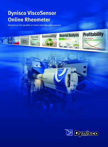
1 SINGLE SCREW EXTRUSIONTWIN SCREW EXTRUSION EXTRUSION PROCESSES SAFETY SINGLE SCREW EXTRUSIONExtrusion may be defined as a process for making a product (an extrudate) byforcing a material through an orifice or die to form a shape, or alternatively,the production of finished, or semi-finished products, using an extruder.Scope of the HandbookThis book will be mainly concerned with the extrusion of thermoplastic products because of their importance in extrusion processes. Thermoplastics areby far the largest group of plastic materials extruded; approximately 65% of allplastics pass through an extruder. As the most popular type of extruder is thesingle screw machine, this book will mainly concentrate on processes basedon that type of machine. Single screw machines are the most popular becausethey are relatively simple, cheap and easily give a continuous output.Extrusion and ThermoplasticsIn extrusion of a thermoplastic, heating first softens the material so that it canbe shaped. The extrusion machine, or extruder does this process. This heatsoftening is called by various names, such as ‘plastication’, ‘plasticization’ or‘thermal softening’. Most extruders are single screw machines. It is the screwwhich forces the material towards, and then through, the die. Shape is imparted by the die, and/or by post-extrusion forming, and then the product is set toshape by cooling it while maintaining its shape. The equipment that does thisis called the post extrusion equipment, while the whole system is called anextrusion line.Extruder ClassificationExtruders may be classified by three figures, for example, 1-60-24. The firstnumber states how many screws the machine has, the second number specifies the screw diameter in millimeters (mm) and, the third number specifiesthe effective screw length as a multiple of the screw diameter. In the examplegiven therefore, a single screw machine is being described that has a screw ofdiameter 60 mm and a length of 24 screw diameters (that is, a L/D ratio of24/1).Machine ConstructionA cut-away drawing of a simple single screw machine is shown in Figure 1.This shows the arrangement of the different parts of the machine. The screwand barrel are the two units that interact to convey the plastic material, meltthe material and then force it through the die. The electric motor drive unit andgearbox rotate the screw at a predetermined speed. Temperature controllerssection 1: introduction to extrusionSECTION 1:INTRODUCTION TO EXTRUSION
2are connected to heating/cooling elements on the barrel to hold the temperature at the set-point temperatures. The ability of the screw and barrel assemblyto extrude a given material is dependent on the characteristics of the plasticsmaterial, the characteristics, or construction, of the screw and barrel, and theconditions under which the system is operated.HopperGear BoxHeatersBarrelScrewDieCooling FansDrive MotorFigure 1. Single Screw Extruder (courtesy of Dr. Harold Giles)Post Extrusion EquipmentOnce the extrudate leaves the die it can either be set to the shape to be produced or have its shape altered and then set to shape. The equipment thatdoes this is called the ‘post extrusion equipment’ or the ‘haul off’ and in termsof size it is usually far larger than the extruder. One reason is that plastics takea long time to cool. This cooling process often determines how fast the linewill operate.Products of ExtrusionThe products of extrusion include: Feedstock for Other Plastics Processes: Extruders are widely used as compounders, or mixers. The output from an extruder compounder is granulatedor chopped to form the feed for another process, such as, injection moldingor extrusion Plastic Film: This is usually used for packaging or sealed into bags Plastic Pipe: Used for gas, water, drains, etc. Plastic Tubing: Used for hose and tubing for automobiles, laboratories, etc. Plastic Insulated Wire and Cable: Used in the home and industryfor appliances, for electric power distribution, communications etc. Profile: Used for tracks, windows, doors, home siding, gaskets, etc. Filaments: Used for brushes, ropes, twine, etc. Sheet: Used for signs, lighting, glazing, etc. Nets: Used for packaging, soil stabilization, etc. Plastic Coated Paper and Metal: Used for packagingCo-ExtrusionCo-extrusion is a process where two, or more, melt streams are combined in adie to produce an extrudate formed from two, or more, materials. The processis now associated with thermoplastics materials although it was first practiced
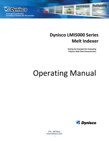
Vented ExtrusionA vented extruder is an extruder that contains a vent, which is used to extractvolatiles from a plastic material during the extrusion process. The water(moisture) and volatiles content in a plastic material may be reduced toacceptable levels by the use of a vented machine. Part of the way along theextrusion barrel the melt is decompressed by reducing the screw root diameter. A vent, through which the vapor escapes, is located at this point in thebarrel (the vent may be plugged and not used when venting is not required).The vapor-free melt is then conveyed towards the die and re-compressed byincreasing the screw root diameter. To ensure that melt does not escapethrough the vent, a dam or torpedo section is incorporated on the screw justbefore the vent. Because of the way that vented machines are constructed (ahigh L/D ratio and a variable screw geometry) and operated, it has been foundthat they produce very good mixing. It should be remembered, however, thatpre-drying of the polymer may be more appropriate, since heating some plastics in contact with water may cause their decomposition, or degradation. TWIN SCREW EXTRUSIONTwin screw extrusion machines or, twin screw extruders, are the simplestexample of multi-screw machines (Figure 2.). The two screws may rotate inthe same direction (co-rotation) or they may rotate in opposite directions(counter or, contra-rotation). The flights of the screws may intermesh or theymay not intermesh. As intermeshing, or partially intermeshing, types ofmachines are the most popular the discussion which follows is restricted tothis type of machine.Uses of Twin-Screw ExtrudersTwin-screw machines have always been popular for certain processes, forexample, where there is a need for a compounding step as well as an extrusion step. This is particularly true for un-plasticized polyvinyl chloride (UPVC).This material is often stabilized against heat degradation by the use of heavymetal compounds (like organic tins, or lead) and such stabilizers are expen-3section 1: introduction to extrusionwith rubbery polymers to produce an extrudate with different colored layers.With thermoplastics, the layers of materials are commonly combined in thedie. The simplest example combines just two layers, for example a coloredlayer on a natural core, which saves on colorant costs. In the packaging industry, films based on three or more layers are now common. Laminating two ormore layers of different polymers together can produce a product that hasbarrier properties far superior to those obtained when only one polymer isused. Frequently, one of the polymers used is a gas or moisture barrier layerbased on polyvinyl alcohol (PVAL). To produce three layered structures, two orthree extruders are usually used. In the blow-molding process it is possible tocombine co-extrusion with bi-axial orientation to produce strong, lightweightbottles which give a long storage life to the products.Layered co-extrusion is not the only type of co-extrusion. Byarranging for the materials to be combined one after the other, a sequentialco-extrudate may be produced. This may consist of a hard thermoplasticmaterial joined to a soft thermoplastic material. Alternatively, two materialsmay be extruded side-by-side, such as a clear material alongside an opaquematerial, to produce sheet to make thermoformed trays.
4Drive MotorGear BoxMainFeedPortDown Stream FeedRemovableTwin Screws withChangeable ElementsRemovableBarrelSectionsFigure 2. Twin Screw Extruder (courtesy of Krupp Werner & Pfleiderer)sive. Thus, for economic reasons, the amount of these heat stabilizers mustbe kept as low as possible. One way of doing this is to compound and extrudein one step. This saves a further heating stage (if the material is first compounded, cooled and then re-extruded). Twin screw machines are widely usedto make UPVC pipe and profiles. Today they are often used to compoundother plastics, or resins, with additives to make compounds for use in otherextrusion or injection molding operations.Operation and CharacteristicsWith a single screw extruder the hopper is filled and the screw takes in thematerial at the rate it wants. Such a scheme, called flood feeding, is often notpossible with twin screw machines. This is because the very positive feedingcharacteristics of twin screw machines may result in very high forces beinggenerated. These forces may be so high that thrust-bearing failure is a realdanger. Twin-screw extruders are therefore often starve fed, resulting in athrough-put independent of screw speed. The average residence time isinversely proportional to the screw speed and feed rate and, therefore,decreases with increasing output. The Specific Energy Consumption, or theenergy input per unit mass of material, also decreases with increasingthroughput. The output is often virtually independent of the size of die used.Because of the mixing action, twin screw machines can achieve more melting,mixing and conveying in a shorter machine length than a single screwmachine. They are, however, much more expensive.Co-Rotating or Counter-Rotating MachinesBoth types of twin screw extruders have distinct advantages that lead to theiruse in specific applications. Counter-rotating machines are used for the extrusion of UPVC and co-rotating machines are used for compounding applications. The counter-rotating machine has very positive material feed and conveying characteristics. The residence time and material temperature control inthe machine are also uniform. However, air entrapment, generation of highpressure, low maximum screw speed and output are disadvantages usuallyencountered. The advantages of the co-rotating machine are that the screwswipe each other clean (self-wiping), high screw speeds and high outputs arepossible, particularly for materials which are not very shear, or heat, sensitive
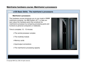
Tapered MachinesBecause of the very positive feeding characteristics of counter-rotating twinscrew machines, very high forces may be generated. These forces can be sohigh that thrust-bearing failure is a real danger. Such machines therefore oftenhave to be starve fed and/or run at low screw speeds. This is because it is difficult to incorporate adequate thrust bearings in the small space available.Tapering the screw diameter from the feed section to the die can increase thespace available. Thus the screws have a larger diameter at the feed end andlarger thrust bearings can then be incorporated, permitting higher outputs.The shear seen at the screw tips is also reduced.Compounding ExtruderThe mixing efficiency of a twin screw extruder can be increased by incorporating mixing elements along the screws. These and other elements may be slotted onto a central shaft to build up the screw section required. On somemachines the length, number, and form of the elements used may be easilychanged. The elements may take various forms such as reversed screwflights, kneading discs, pins, etc. Thus, in the process, the material may beheat-softened in an extrusion section, passed into the mixing section, and thenconveyed into another section. This process may be repeated several times,for example in devolatilizing extruders or machines used to carry out chemicalreactions.Cascade ExtruderThe simplest type of cascade extruder consists of two single screw extruders(two screw and barrel assemblies, one mounted above the other) where theoutput (melt) from the first machine feeds the second. A passageway that maybe vented for devolatization connects the two screw assemblies. This type ofmachine may also be classified as a vented extruder. It offers the advantagethat each screw may be driven at a separate speed, so their output can bematched. Valves may be also used to optimize the output from each stage.Gear PumpA gear pump is a very simple twin-screw extruder that moves a fluid materialthrough the action of two intermeshing gears (Figure 3.). A gear pumpextruder may be used to produce fibers from polymers that have low viscosities at their processing temperatures. Examples of this type of polymer arepolyamides, polypropylenes, or PET.A gear pump fitted between the end of the barrel and the die of asingle-screw extruder will produce a steady high pressure and a more consistent and higher output from the die. Thus, a gear pump can make the outputof an extruder virtually independent of back-pressure and, within reason, ofscrew wear. As the accuracy of output is improved, significant down gaugingof the extrudate is possible (approximately 10%). Since the gear pump is usedto build up pressure in the die ( 70 MPa/10,000 psi), the screw is notrequired to develop high pressures. This usually results in a reduction in melt5section 1: introduction to extrusion(such as PE). Less screw and barrel wear are also found. The output is, however, dependent on die-head pressure and at high pressures the material residence time distribution becomes broader (the clearances between the flanks ofthe screws are usually greater for this type of machine). At the high shearrates possible in this type of machine, this non-uniform residence time canresult in decomposition of heat sensitive materials. However, the greater interchannel flow results in better mixing or compounding.
6temperatures (approximately 10 C/18 F). The combination of down gaugingand melt temperature
Sheet: Used for signs, lighting, glazing, etc. Nets: Used for packaging, soil stabilization, etc. Plastic Coated Paper and Metal: Used for packaging Co-Extrusion Co-extrusion is a process where two, or more, melt streams are combined in a die to produce an e