Transcription
TECHNICAL GUIDESHAFTLINER FOR SHAFTWALL/STAIRWELL SYSTEMS
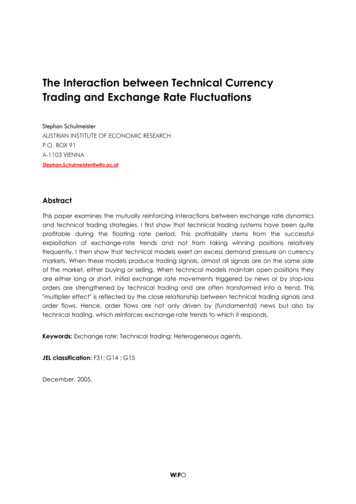
DensGlass Shaftliner Shaftwall/Stairwell SystemsProduct OverviewFiberglass MatsMoisture-ResistantGypsum CoreDensGlass Shaftliner 2016 Georgia-Pacific Gypsum LLCTable of ContentsProduct Overview. . . . . . . . . . . . . 2Sustainability . . . . . . . . . . . . . . . . 4Installation Instructions . . . . . . . . 5Recommendations . . . . . . . . . . . . 6Design Summary Vertical . . . . . . 7Design Summary Horizontal . . . 12Maximum Horizontal Spans. . . . 13DensGlass Shaftliner has fiberglass mats for superior mold and moisture resistancecompared to paper-faced shaftliners. Fiberglass mats eliminate a potential food source for mold and may reduce remediationand scheduling delays associated with paper-faced shaftliners. Replaces traditional paper-faced shaftliner. Backed with a limited warranty against delamination and deterioration for up to 12 monthsof exposure to normal weather conditions.**For complete warranty details, visit www.buildgp.com/warranties.2-Hour Vertical and HorizontalShaftwalls Around HorizontalMembranes and Ducts. . . . . . . . 13When tested, as manufactured, in accordance with ASTM D3273, DensGlass Shaftlinerpanels have scored a 10, the highest level of performance for mold resistance under theASTM D3273 test method.Hoistway Enclosures . . . . . . . . . 14The score of 10, in the ASTM D3273 test, indicates no mold growth in a 4-week controlledlaboratory test. The mold resistance of any building product when used in actual job siteconditions may not produce the same results as were achieved in the controlled, laboratorysetting. No material can be considered mold proof. When properly used with good design,handling and construction practices, Dens Brand gypsum products provide increased moldresistance compared to standard paper-faced wallboard. For additional information, go towww.buildgp.com/safetyinfo.Sound Chart . . . . . . . . . . . . . . . . 14Limiting Heights. . . . . . . . . . . . . 15Maximum Section Properties . . 15Door Frame Details . . . . . . . . . . 16Wall Frame Details . . . . . . . . . . 17Rails/Chute/Beam Details . . . . . 18HVAC Duct Detail. . . . . . . . . . . . 19Delivery, Handlingand Storage . . . . . . . . . . . . . . . . 19DensGlass Shaftliner is listed as mold resistant in UL Environment’s Sustainable ProductGuide. This validation means DensGlass Shaftliner, which features fiberglass facingsinstead of paper facings, resists mold growth. The microbial-resistant test is based onASTM D6329, a testing standard set by ASTM International, an agency which developstesting guidelines and procedures for building materials, products, systems and services.Recommendations andLimitations for Use. . . . . . . . . . . 192 For latest information and updates:Technical Service Hotline 1.800.225.6119 or www.gpgypsum.comCAUTION: For product fire, safety and use information,go to buildgp.com/safetyinfo.
DensGlass Shaftliner Shaftwall/Stairwell SystemsDensGlass Shaftliner PanelIn buildings around the world, our lightweight, maintenance-free gypsum shaftwall/stairwell enclosures serve as the perfectalternative for heavy masonry construction in building cores. In addition, DensGlass Shaftliner shaftwall/stairwell assembliessave space, go up quickly and don’t delay construction during cold weather.Space-saving DensGlass Shaftliner shaftwall/stairwell enclosures are designed for elevator and air shafts, stairwells andmechanical rooms in industrial buildings where greater wall heights are common and as firewalls between office, warehouseand manufacturing areas. They are also used as horizontal membranes for corridor and stairway ceilings and under mechanicalequipment where fire ratings are required and normal suspension support may be difficult.Easy InstallationBecause the shaftwall assemblies are built from one side only, there’s no need to access the inside of the shaft. The strong,C-T, C-H or I steel framing goes up quickly. Most configurations require only two steel components and two types of gypsumboard. That makes these systems ideal for furred chases and interior partitions where fire ratings are required for exterior wallsand access is restricted. Engineered for durability, these systems withstand air-pressure surges of high-speed elevators aswell as lateral impact of stairway doors.Built-In EconomyGypsum shaftwall/stairwell systems typically cost less than masonry. Contractors also save money, since the shaftwall/stairwellenclosures don’t require expensive structural framing or concrete construction.Building CodeGeorgia-Pacific Gypsum shaftwall/stairwell systems conform to the requirements of the IBC. Hardening of exit stairway andpassageway enclosures, and elevator shaft enclosures, are required for all buildings more than 420 feet high and for buildings75-420 feet high where failure of the enclosure would substantially jeopardize human life, including facilities such as hospitals.This assembly may also require the installation of DensArmor Plus Abuse-Resistant or Impact-Resistant panels.Reliable Steel ComponentsThe two primary framing components in the DensGlass Shaftliner shaftwall/stairwell system are slotted C-T, C-H or I studs andJ tracks, manufactured from galvanized steel that meets the requirements of ASTM C645 and A 924.The 2-1/2” (64 mm) steel framing system retains the popular 3-1/2” (89 mm) wall thickness with a two-hour fire rating(see pages 7 and 8) to accommodate standard door framing dimensions. The steel stud offers a unique feature — slotting in theweb of the stud. Tests have demonstrated that these slots effectively improve resistance to thermal and noise transmissions.The 2-1/2” (64 mm) stud provides a 1-1/2” (38 mm) air cavity for services. Studs are fitted between top and bottom J tracks.Use J tracks for all closure details, including duct and door openings, abutments, intersections, etc. No other special metalcomponents are required.Studs are automatically spaced 24” (610 mm) o.c. maximum with installation of shaftliner panels.The data relating to fire and sound-tested assemblies is based on the characteristics, properties and performance of materialsand systems obtained under controlled test conditions as set forth under the appropriate ASTM standard, such as E119 (fire),E90 (sound) or E72 (structural).CAUTION: For product fire, safety and use information,go to buildgp.com/safetyinfo.For latest information and updates:Technical Service Hotline 1.800.225.6119 or www.gpgypsum.com3
DensGlass Shaftliner Shaftwall/Stairwell SystemsGeorgia-Pacific Gypsum and SustainabilityGeorgia-Pacific Gypsum’s definition of sustainability is meeting the needs of society today without jeopardizing our ability to do soin the future. We are committed to using resources efficiently to provide innovative products and solutions that meet the needsof customers and society, while operating in a manner that is environmentally and socially responsible, and economically sound.We continue to focus on: Improving energy efficiency at our manufacturing plants Seeking opportunities to reduce water use, and to reuse water more efficiently Finding cost effective ways to further reduce air emissions Recovering and reusing materials that otherwise would end up in landfills.Green building codes, standards, and programs have established themselves across the country. They promote the use ofproducts which contribute to the performance of the building, along with minimizing environmental and human health impactsover the life of the building. Because we embrace product performance and operate in an environmentally, socially andeconomically sound manner, owners and architects can be proud of the structures they build using our products.Many of our products contribute to LEED and other green building codes, standards or program credits or requirements. Pleaserefer to www.gpgypsum.com for recycled content, regional materials and low emitting materials information or use our on-lineLEED calculator to calculate contribution for a specific credit. For general information on sustainability, visitwww.buildgp.com/sustainability.4 For latest information and updates:Technical Service Hotline 1.800.225.6119 or www.gpgypsum.comCAUTION: For product fire, safety and use information,go to buildgp.com/safetyinfo.
DensGlass Shaftliner Shaftwall/Stairwell SystemsInstallation Instructions1.Secure J track as perimeter framing on floor and plumb to ceiling and sides. Attach with suitable fasteners, spaced notmore than 24” (610 mm) o.c.2.Plan the stud layout 24” (610 mm) o.c. and adjust the spacing at either end so the terminal stud will not fall closerthan 8” (203 mm) from the end (is recommended). Pieces less than 8” (203 mm) may pose handling and installationproblems such as cracking and breaking.3.1” (25.4 mm) DensGlass Shaftliner panels should be cut no more than 3/4” (19 mm) for WHI designs or 1” (25.4 mm) forUL designs less than the total height of the framed section. Plumb the first panel flush against the long side of the J trackand secure with 1-5/8” (41 mm) Type S screws 24” (610 mm) o.c. or bend out tabs in J track to secure panels in place.DensGlass Shaftliner panels may be installed with either side facing out, however some authorities may require labeling tobe visible.4.Insert a C-T, C-H or I stud, cut 3/4” (19 mm) less than the overall height, into the top and bottom J track and fit tightlyover the previously installed 1” (25.4 mm) panel.5.Install the next 1” (25.4 mm) DensGlass Shaftliner panel inside the J track and within the tabs of the C-T, C-H or I stud.Note that the edges of the panel are beveled to help guide the panel into the slotted and tabbed section of the stud.6.Progressively install succeeding studs and panels as described above until the wall section is enclosed. The final panelsection may be secured with 1-5/8” (41 mm) Type S screws or tabs from the J track at 24” (610 mm) o.c.7.For doors, ducts or other large penetrations or openings, install J track as perimeter framing. Use true 20-gauge (33 mils)track with a 3” (76 mm) back leg for elevator doors and block cavity with 12” (305 mm) wide gypsum board filler strips fordoors exceeding 7’ 0” (2134 mm) in height. Attach metal intersections with a 3/8” (9.5 mm) pan head screw.8.1” (25.4 mm) DensGlass Shaftliner panels may be abutted, spliced or stacked within the cavity. The shorter panelshould be a minimum 2’ (610 mm) tall to engage two stud tabs on each panel edge. Joints of adjacent panels should bealternately stacked or staggered to prevent a continuous horizontal joint. Staggered Shaftliner joints are not required forUL V473 1 hour Shaftwall.9.Fire tests were conducted without back blocking of shaftliner joints. Install factory cut edges back to back for all WHIdesigns and UL 1 hour V473.*10. For WHI GP/WA 120-01 finished 2 hour one side, install the base layer of 1/2” (12.7 mm) ToughRock Fireguard C gypsumboard or 1/2” (12.7 mm) DensArmor Plus Interior Panel horizontally with 1” (25.4 mm) Type S or S-12 screws spaced 24”(610 mm) o.c. starting 3” (76 mm) from top and bottom. (5/8” (15.9 mm) DensArmor Plus Fireguard gypsum panels may beused in lieu of 1/2” (12.7 mm) ToughRock Fireguard C gypsum board, (if desired.) The horizontal joints should be offset fromany splice joints in the shaftliner panels by at least 12” (305 mm). Install the face layer vertically with 1-5/8” (41 mm) TypeS or S-12 screws spaced 12” (305 mm) o.c. starting 6” (152 mm) from top and bottom. (All edge and end joints should beoffset from the base layer by 24” (610 mm) o.c.)*11. For WHI GP/WA 120-02, finished 2 hour both sides, each side must be installed vertically with 1” (25.4 mm) Type S orS-12 screws spaced 12” (305 mm) starting 6” (152 mm) from top and bottom and with vertical joints offset 24” (610 mm).Edges and ends on opposite sides offset 24” (610 mm) o.c.*12. For WHI GP/WA 60-01, finished 1 hour one side, apply the 5/8” (15.9 mm) ToughRock Fireguard X gypsum board or 5/8”(15.9 mm) DensArmor Plus Interior Panel horizontally or vertically with 1” (25.4 mm) Type S or S-12 screws spaced 12”(305 mm) o.c.*13. For UL V473, 2 hour finished one side, install the base layer of 5/8” (15.9 mm) ToughRock Fireguard X gypsum board or 5/8”(15.9 mm) DensArmor Plus Interior Panel horizontally or vertically with 1” (25.4 mm) Type S screws spaced 24” (610 mm)o.c. Face layer applied horizontally or vertically, attached with 1-5/8” (41 mm) Type S screws spaced 12” (305 mm) o.c.(All end and edge joints should be offset from the base layer by 24” (610 mm) o.c.)*14. For UL V473, 1 hour, apply 5/8” (15.9 mm) ToughRock Fireguard X gypsum board or 5/8” (15.9 mm) DensArmor Plus InteriorPanel horizontally or vertically. Vertical joints centered over studs. Attach with 1” (25.4 mm) Type S or S-12 screws spaced 8”(203 mm) o.c.15. When used as HVAC ducts, consult with HVAC engineer regarding level of caulking and sealant required. All jointson face layers are to be taped and finished and fasteners finished with joint compound meeting ASTM C475. Allpenetration openings are to be filled with firestopping sealants.16. For more information on firestopping through penetrations in shaftwall systems or head of wall shaftwall details, consult theUL directory or other fire testing agencies’ listings.*Consult the UL or WHI listing or test report for complete assembly information.CAUTION: For product fire, safety and use information,go to buildgp.com/safetyinfo.For latest information and updates:Technical Service Hotline 1.800.225.6119 or www.gpgypsum.com5
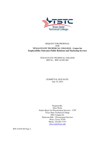
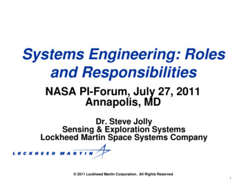
DensGlass Shaftliner Shaftwall/Stairwell SystemsSee individual fire test listings for approved studs. (Drawings are not to scale.)C-T Stud DetailC-H Stud Detail1-5/8”(41 mm)I Stud Detail1-3/8”(35 mm)1” (25.4 mm)1-1/2”(38 mm)1” (25.4 mm)1” (25.4 mm)2-1/2”,4” or 6”(64, 102or 152 mm)2-1/2”, 4” or 6”(64, 102 or 152 mm)1-3/8”(35 mm)2-1/2”, 4” or 6”(64, 102 or 152 mm)1-1/2”(38 mm)J TrackJ-L Corner3/4” (19 mm)3”(76 mm)2-1/2”, 4” or 6”(64, 102 or 152 mm)2-1/4”(57 mm)1” (25.4 mm)1” (25.4 mm)2-1/2”, 4” or 6”(64, 102 or 152 mm)2-1/2”, 4” or 6”(64, 102 or 152 mm)Recommendations Use a fastening plate to secure the J track whenever fasteners are closer than 4” (102 mm) to the end of the assembly.Setting the plate at the time of concrete construction will avoid spalling by mechanical fasteners. In structural steel-frame construction, install J track sections before applying spray-on fireproofing. Items to be anchored to the wall (cabinets, sinks, handrails, etc.) should be fastened to the C-T, C-H or I studs or to platessecured behind or between layers of gypsum board. (See handrail illustration on page 18.) Joint compounds should be applied at ambient temperatures above 50 F (10 C) with adequate ventilation. Use Type S screws for true 25-gauge (18 mils) steel framing. Use Type S-12 screws for true 20-gauge (33 mils) (or heavier)steel framing. It is important that the job structural engineer approves the type, size and maximum spacing of track fasteners to meet thedesign load requirements.6 For latest information and updates:Technical Service Hotline 1.800.225.6119 or www.gpgypsum.comCAUTION: For product fire, safety and use information,go to buildgp.com/safetyinfo.
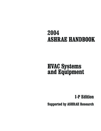
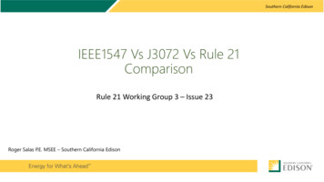
DensGlass Shaftliner Shaftwall/Stairwell SystemsDesign Summary Vertical ApplicationsDensGlass Shaftliner is UL and ULC certified as Type DGUSL and included in numerous assembly designs listed by UL andULC for hourly fire resistance ratings.In addition, DensGlass Shaftliner is classified as “Type X” in accordance with ASTM C1658 and may replace 1” (25.4 mm)gypsum shaftliner panels specified as Type X in generic fire-rated wall assemblies. Generic systems in the GA-600 FireResistance Design Manual are applicable to the products of any manufacturer, including Georgia-Pacific Gypsum, providedthey meet certain standards set forth in such manual, such as Type X gypsum board per applicable ASTM standard withspecified thickness and size described in the design. “Type X” as used in this technical guide designates gypsum boardmanufactured and tested in accordance with specific ASTM standards for increased fire resistance beyond regular gypsumboards. Please consult the ASTM standard for the specific product (for example, ASTM C1658 for glass mat gypsum panels)for further information and significance of use.The following design assemblies are for illustrative purposes only. Consult the appropriate fire resistancedirectory for complete assembly information. For additional fire safety information concerning DensGlassShaftliner, visit www.buildgp.com/safetyinfo.Proprietary GA-600 Designs: Assemblies listed as proprietary in the GA-600 Fire Resistance Design Manual only list oneproduct per manufacturer and may not include all products referenced in the illustrations below. Please consult the specifiedUL, ULC, cUL or other fire listing or test for a complete list of approved products.1-Hour Fire RatingDesign Reference: WHI Design GP/WA 60-0140-44 STC Sound Trans.Test Reference: RAL TL 09-357Approx. Weight: 7 psf (34 Kg/m2)One layer 1” (25.4 mm) ToughRock Shaftliner or 1” (25.4 mm) DensGlass Shaftlinerinserted between 2-1/2” (64 mm) floor and ceiling J runners with H section of 2-1/2”(64 mm) C-H, C-T, or I studs between panels. Panels attached to the top J runner withthree 1-5/8” (41 mm) Type S screws, one at each edge and one at mid width of theboard. Attach panels to vertical J runners with 1-5/8” (41 mm) Type S screws spaced 24”(610 mm) o.c.OPPOSITE SIDE: 5/8” (15.9 mm) ToughRock Fireguard X gypsum board or 5/8” (15.9mm) DensArmor Plus Fireguard gypsum panels applied vertically or horizontally to studswith 1” (25.4 mm) Type S drywall screws 12” (305 mm) o.c.C-T, C-H or I Stud2-1/2” (64 mm)4” (102 mm)6” (152 mm)Wall Thickness3-1/8” (80 mm)4-5/8” (118 mm)6-5/8” (168 mm)1-Hour Fire RatingDesign Reference: UL V473, cUL V473,GA WP 685140-44 STC Sound Trans.Test Reference: RAL TL 09-357Approx. Weight: 7 psf (34 Kg/m2)Sound tested with 1-1/2” (38 mm) glass fiber insulation friction fit in stud cavity andwith the 5/8” (15.9 mm) proprietary type X gypsum wallboard applied with screwsspaced 12” (305 mm) o.c. (NLB)One layer 1” (25.4 mm) ToughRock Shaftliner or 1” (25.4 mm) DensGlass Shaftlinerinserted between 2-1/2” (64 mm) floor and ceiling J runners with H section of 2-1/2”(64 mm) C-H, C-T, or I studs between panels.OPPOSITE SIDE: One layer 5/8” (15.9 mm) ToughRock Fireguard X Gypsum Board or5/8” (15.9 mm) DensArmor Plus Fireguard interior panels applied vertically or horizontallyto studs with 1” (25.4 mm) Type S drywall screws 8” (203 mm) o.c.C-T, C-H or I Stud2-1/2” (64 mm)4” (102 mm)6” (152 mm)Wall Thickness3-1/8” (80 mm)4-5/8” (118 mm)6-5/8” (168 mm)CAUTION: For product fire, safety and use information,go to buildgp.com/safetyinfo.For latest information and updates:Technical Service Hotline 1.800.225.6119 or www.gpgypsum.com7
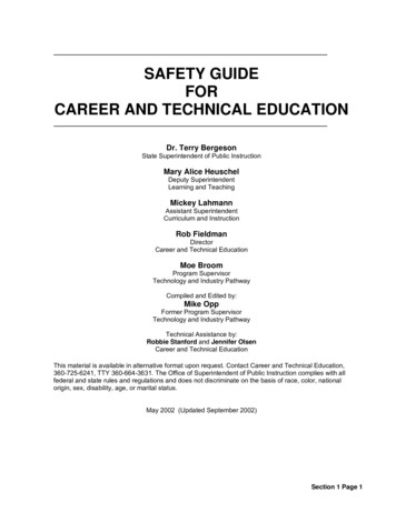
DensGlass Shaftliner Shaftwall/Stairwell SystemsDesign Summary Vertical Applications continued2-Hour Fire RatingDesign Reference: UL V473, cUL V473,GA WP 705450-54 STC Sound Trans.Test Reference: RAL TL 09-358Approx. Weight: 9 psf (44 Kg/m2)Sound tested with 1-1/2” (38 mm) glass fiber insulation friction fit in stud space. (NLB)One layer 1” (25.4 mm) ToughRock Shaftliner or 1” (25.4 mm) DensGlass Shaftlinerinserted between 2-1/2” (64 mm) floor and ceiling J runners with H section of 2-1/2”(64 mm) C-H, C-T, or I studs between panels.OPPOSITE SIDE: Base layer 5/8” (15.9 mm) ToughRock Fireguard X Gypsum Boardor 5/8” (15.9 mm) DensArmor Plus Fireguard interior panels applied vertically orhorizontally to studs with 1” (25.4 mm) Type S drywall screws 24” (610 mm) o.c.Face layer 5/8” (15.9 mm) ToughRock Fireguard X Gypsum Board or 5/8” (15.9 mm)DensArmor Plus Fireguard interior panels applied vertically to studs with 1-5/8” (41 mm)Type S drywall screws 12” (305 mm) o.c. along top and bottom tracks and 12” (305 mm)o.c. at vertical joints and intermediate studs. Face layer joints offset 24” (610 mm) frombase layer joints.C-T, C-H or I StudWall Thickness2-Hour Fire RatingDesign Reference: UL V473, ULC W481,cUL V473, GA WP 70592-1/2” (64 mm)3-3/4” (95 mm)4” (102 mm)5-1/4” (133 mm)6” (152 mm)7-1/4” (184 mm)50-54 STC Sound Trans.Test Reference: RAL TL 09-358Approx. Weight: 9 psf (44 Kg/m2)Sound tested with 1-1/2” (38 mm) glass fiber insulation friction fit in stud space. (NLB)One layer 1” (25.4 mm) ToughRock Shaftliner or 1” (25.4 mm) DensGlass Shaftlinerinserted between 2-1/2” (64 mm) floor and ceiling J runners with H section of 2-1/2”(64 mm) C-H, C-T, or I studs between panels.One layer 5/8” (15.9 mm) ToughRock Fireguard X Gypsum Board or 5/8” (15.9 mm)DensArmor Plus Fireguard interior panels applied vertically to each side with 1”(25.4 mm) Type S drywall screws 12” (305 mm) o.c.C-T, C-H or I StudWall Thickness2-Hour Fire RatingDesign Reference: UL U428, GA WP 70512-1/2” (64 mm)3-3/4” (95 mm)4” (102 mm)5-1/4” (133 mm)6” (152 mm)7-1/4” (184 mm)50-54 STC Sound Trans.Test Reference: RAL TL93-181Approx. Weight: 9 psf (44 Kg/m2)Sound tested with 1-1/2” (38 mm) glass fiber insulation in stud space. (NLB)One layer 1”x 24” (25.4 mm x 610 mm) DensGlass Shaftliner or ToughRock Shaftliner gypsum panels inserted between 2-1/2” (64 mm) floor and ceiling J runnerswith T section of 2-1/2” (64 mm) steel C-H or C-T studs between panels.OPPOSITE SIDE: Base layer 1/2” (12.7 mm) DensArmor Plus Fireguard C or 1/2”(12.7 mm) ToughRock Fireguard C gypsum wallboard applied at right angles to studswith 1” (25.4 mm) Type S drywall screws 24” (610 mm) o.c. Face layer 1/2” (12.7mm) DensArmor Plus Fireguard C or 1/2” (12.7 mm) ToughRock Fireguard C gypsumwallboard applied parallel to studs with 1-5/8” (41 mm) Type S drywall screws 12”o.c.(305 mm)8 For latest information and updates:Technical Service Hotline 1.800.225.6119 or www.gpgypsum.comCAUTION: For product fire, safety and use information,go to buildgp.com/safetyinfo.
DensGlass Shaftliner Shaftwall/Stairwell SystemsDesign Summary Vertical Applications continued2-Hour Fire RatingDesign Reference: UL U429, GA WP 705250-54 STC Sound Trans.Test Reference: RAL TL93-181Approx. Weight: 9 psf (44 Kg/m2)Sound tested with 1-1/2” (38 mm) glass fiber insulation in stud space. (NLB)One layer 1”x 24” (25.4 mm x 610 mm) DensGlass Shaftliner or ToughRock Shaftlinergypsum panels inserted between 2-1/2” (64 mm) floor and ceiling J runners withT section of 2-1/2” (64 mm) steel C-H or C-T studs between panels. Face layer 1/2”(12.7 mm) DensArmor Plus Fireguard C or 1/2” (12.7 mm) ToughRock Fireguard Cgypsum wallboard applied parallel to studs with vertical joints midway between studsand laminated to the 1/2” (12.7 mm) DensArmor Plus Fireguard C or 1/2” (12.7 mm)ToughRock Fireguard C gypsum wallboard with 4” (101.6 mm) wide strips of tapingcompound at wallboard perimeter and vertical centerline. 1-1/2” (38 mm) Type G drywallscrews 24” o.c. located 1-1/2” (38 mm) back from wallboard edges and at verticalcenterline.OPPOSITE SIDE: One layer 1/2” (12.7 mm) DensArmor Plus Fireguard C or 1/2” (12.7mm) ToughRock Fireguard C gypsum wallboard applied at right angles to studs with 1”(25.4 mm) Type S drywall screws 24” (610 mm) o.c.2-Hour Fire RatingDesign Reference: UL V433-System B,GA WP 7255Approx. Weight: 9 psf (44 Kg/m2)One layer 1”x 24” (25.4 mm x 610 mm) DensGlass Shaftliner or ToughRock Shaftliner gypsum panels inserted between 2-1/2” (64 mm) floor and ceiling J runnerswith tab flange section of 2-1/2” (64 mm) steel I studs between panels.One layer 1/2” (12.7 mm) ToughRock Fireguard C gypsum wallboard applied parallelto each side with 1” (25.4 mm) Type S drywall screws 12” (305 mm) o.c. Vertical jointsare offset one stud space each side (NLB)2-Hour Fire RatingDesign Reference: UL W437System ASystem AOne layer 1”x 24” (25.4 mm x 610 mm) DensGlass Shaftliner or ToughRock Shaftliner gypsum panels inserted between 2-1/2” (64 mm) floor and ceiling J runnerswith tab flange section of 2-1/2” (64 mm) steel I studs between panels.OPPOSITE SIDE: Base layer 1/2” (12.7 mm) ToughRock Fireguard C wallboardapplied at right angles to studs with 1” (25.4 mm) Type S drywall screws 24” (610mm) o.c. Face layer 1/2” (12.7 mm) ToughRock Fireguard C gypsum wallboardapplied parallel to studs with 1-5/8” (41 mm) Type S drywall screws 12” (305 mm) o.c.System BSystem BCAUTION: For product fire, safety and use information,go to buildgp.com/safetyinfo.One layer 1”x 24” (25.4 mm x 610 mm) DensGlass Shaftliner or ToughRock Shaftliner gypsum panels inserted between 2-1/2” (64 mm) floor and ceiling J runnerswith tab flange section of 2-1/2” (64 mm) steel I studs between panels. One layer1/2” (12.7 mm) ToughRock Fireguard C gypsum wallboard applied parallel to eachside with 1” (25.4 mm) Type S drywall screws 12” (305 mm) o.c. Vertical joints areoffset one stud space each side (NLB)For latest information and updates:Technical Service Hotline 1.800.225.6119 or www.gpgypsum.com9
DensGlass Shaftliner Shaftwall/Stairwell SystemsDesign Summary Vertical Applications continued2-Hour Fire RatingDesign Reference: UL U529Support angles- 1” ( 25.4 mm) by 2” (50.8 mm) steel “L” runners to support the wallalong the perimeter. Angles mechanically attached to structure spaced 24” (610 mm) o.c.1/2” (12.7 mm) DensArmor Plus Fireguard C or 1/2” (12.7 mm) ToughRock FireguardC gypsum wallboard applied vertically and secured to support angles with 1” (25.4mm) Type S drywall screws spaced 12” (305 mm) o.c. The wallboard is laminated*and secured to each side of the 1”x 24” (25.4 mm x 610 mm) DensGlass Shaftliner orToughRock Shaftliner panel also applied vertically (with wallboard joints centered overliner panels) with 1-1/2” (38 mm) Type G steel screws spaced 24” (610 mm) o.c. in bothdirections. Joints of wallboard layers offset 24” (610 mm).*Joint compound applied uniformly to both surfaces of 1”x 24” (25.4 mm x 610 mm)DensGlass Shaftliner or ToughRock Shaftliner gypsum panels with a notched spreader1/4” x 1/4” (6.35 mm x 6.35 mm) spaced 1” (25.4 mm) o.c.2-Hour Fire RatingDesign Reference:WHI Design GP/WA 120-01, GA WP 7054.450-54 STC Sound Trans.Test Reference: RAL TL 09-360Approx. Weight: 9 psf (44 Kg/m2)Sound tested with 1-1/2” (38 mm) glass fiber insulation friction fit in stud space. (NLB)One layer 1” (25.4 mm) ToughRock Shaftliner or 1” (25.4 mm) DensGlass Shaftlinerinserted between 2-1/2” (64 mm) floor and ceiling J runners with H section of 2-1/2”(64 mm) C-H, C-T, or I studs between panels.OPPOSITE SIDE: Base layer 1/2” (12.7 mm) ToughRock Fireguard C Gypsum Boardor 1/2” (12.7 mm) DensArmor Plus Fireguard C interior panels applied horizontally tostuds with 1” (25.4 mm) Type S drywall screws 24” (610 mm) o.c. and 3” (76 mm) fromfloor and ceiling runners. Face layer 1/2” (12.7 mm) ToughRock Fireguard C GypsumBoard or 1/2” (12.7 mm) DensArmor Plus Fireguard C interior panels applied verticallyto studs with 1-5/8” (41 mm) Type S drywall screws 12” (305 mm) o.c. and 6” (152 mm)from floor and ceiling runners. Joints offset 24” (610 mm) from base layer joints.C-T, C-H or I StudWall Thickness2-Hour Fire RatingDesign Reference:WHI Design GP/WA 120-02, GA WP 70734” (102 mm)5” (127 mm)6” (152 mm)7” (178 mm)45-49 STC Sound Trans.Test Reference: RAL TL 09-359Approx. Weight: 9 psf (44 Kg/m2)Sound tested with 1-1/2” (38 mm) glass fiber insulation friction fit in stud space. (NLB)One layer 1” (25.4 mm) ToughRock Shaftliner or 1” (25.4 mm) DensGlass Shaftlinerinserted between 2-1/2” (64 mm) floor and ceiling J runners with H section of 2-1/2”(64 mm) C-H, C-T, or I studs between panels.One layer 1/2” (12.7 mm) ToughRock Fireguard C Gypsum Board or DensArmor Plus Fireguard C interior panels applied vertically to each side with 1” (25.4 mm) Type Sdrywall screws 12” (305 mm) o.c. Joints staggered 24” (610 mm) on opposite sides.C-T, C-H or I StudWall Thickness10 For latest information and updates:2-1/2” (64 mm)3-1/2” (89 mm)Technical Service Hotline 1.800.225.6119 or www.gpgypsum.com2-1/2” (64 mm)3-1/2” (89 mm)4” (102 mm)5” (127 mm)6” (152 mm)7” (178 mm)CAUTION: For product fire, safety and use information,go to buildgp.com/safetyinfo.
DensGlass Shaftliner Shaftwall/Stairwell SystemsDesign Summary Vertical Applications continued3-Hour Fire RatingDesign Reference: WHI GP/WA 180-01,GA WP 742250-54 STC Sound Trans.Test Reference: RAL TL 09-360Approx. Weight: 12 psf (59 Kg/m2)Sound tested with 1-1/2” (38 mm) glass fiber insulation friction fit in stud space. (NLB)One layer 1” (25.4 mm) ToughRock Shaftliner or 1” (25.4 mm) DensGlass Shaftlinerinserted between 2-1/2” (64 mm) floor and ceiling J runners with H section of 2-1/2”(64 mm) C-H, C-T, or I studs between panels.OPPOSITE SIDE: Base layer 5/8” (15.9 mm) ToughRock Fireguard C Gypsum Board or5/8” (15.9 mm) DensArmor Plus Fireguard C interior panels applied horizontally to studswith 1” (25.4 mm) Type S drywall screws 24” (610 mm) o.c. Second layer 5/8” (15.9 mm)ToughRock Fireguard C Gypsum Board or 5/8” (15.9 mm) DensArmor Plus Fireguard Cinterior panels applied horizontally to studs with 1-5/8” (41 mm) Type S drywall screws16” (406 mm) o.c. at studs and 1-1/2” (38 mm) Type G drywall screws 16” (406 mm)o.c. placed 2” (51 mm) from any vertical joints. Face layer 5/8” (15.9 mm) ToughRock Fireguard C Gypsum Board or 5/8” (15.9 mm) DensArmor Plus Fireguard C interior panelsapplied vertically to studs with 2-1/4” (57 mm) Type S drywall screws 12” (305 mm) o.c.at studs and 1-1/2” (38 mm) Type G drywall screws 12” (305 mm) o.c. placed 2” (51 mm)from either side of horizontal joints.C-T, C-H or I Stud 2-1/2” (64 mm)4” (102 mm)6” (152 mm)Wall Thickness4-3/8” (111 mm)5-7/8” (149 mm)7-7/8” (200 mm)3-Hour Fire RatingDesign Reference: GP/GBA 180-02Approx. wt.10 psf (49 Kg/m2)Two layers 1” (25.4 mm) x 24” (610 mm) ToughRock Shaftliner or 1” (25.4 mm)DensGlass Shaftliner inserted between 2” (51 mm) floor and ceiling runner
board or 1/2” (12.7 mm) DensArmor Plus Interior Panel horizontally with 1” (25.4 mm) Type S or S-12 screws spaced 24” (610 mm) o.c. starting 3” (76 mm) from top and bottom. (5/8” (15.9 mm) DensArmor Plus