Transcription
NASA/TM—2012-217404Enhancement of Aviation Fuel Thermal StabilityCharacterization Through Applicationof EllipsometrySamuel Tucker Browne, Hubert Wong, and Cameron Branch HindererGlenn Research Center, Cleveland, OhioJennifer KlettlingerGlenn Research Center, Cleveland, OhioMarch 2012
NASA STI Program . . . in ProfileSince its founding, NASA has been dedicated to theadvancement of aeronautics and space science. TheNASA Scientific and Technical Information (STI)program plays a key part in helping NASA maintainthis important role.The NASA STI Program operates under the auspicesof the Agency Chief Information Officer. It collects,organizes, provides for archiving, and disseminatesNASA’s STI. The NASA STI program provides accessto the NASA Aeronautics and Space Database andits public interface, the NASA Technical ReportsServer, thus providing one of the largest collectionsof aeronautical and space science STI in the world.Results are published in both non-NASA channelsand by NASA in the NASA STI Report Series, whichincludes the following report types: TECHNICAL PUBLICATION. Reports ofcompleted research or a major significant phaseof research that present the results of NASAprograms and include extensive data or theoreticalanalysis. Includes compilations of significantscientific and technical data and informationdeemed to be of continuing reference value.NASA counterpart of peer-reviewed formalprofessional papers but has less stringentlimitations on manuscript length and extent ofgraphic presentations.TECHNICAL MEMORANDUM. Scientificand technical findings that are preliminary orof specialized interest, e.g., quick releasereports, working papers, and bibliographies thatcontain minimal annotation. Does not containextensive analysis.CONTRACTOR REPORT. Scientific andtechnical findings by NASA-sponsoredcontractors and grantees. CONFERENCE PUBLICATION. Collectedpapers from scientific and technicalconferences, symposia, seminars, or othermeetings sponsored or cosponsored by NASA. SPECIAL PUBLICATION. Scientific,technical, or historical information fromNASA programs, projects, and missions, oftenconcerned with subjects having substantialpublic interest. TECHNICAL TRANSLATION. Englishlanguage translations of foreign scientific andtechnical material pertinent to NASA’s mission.Specialized services also include creating customthesauri, building customized databases, organizingand publishing research results.For more information about the NASA STIprogram, see the following: Access the NASA STI program home page athttp://www.sti.nasa.gov E-mail your question via the Internet to help@sti.nasa.gov Fax your question to the NASA STI Help Deskat 443–757–5803 Telephone the NASA STI Help Desk at443–757–5802 Write to:NASA Center for AeroSpace Information (CASI)7115 Standard DriveHanover, MD 21076–1320
NASA/TM—2012-217404Enhancement of Aviation Fuel Thermal StabilityCharacterization Through Applicationof EllipsometrySamuel Tucker Browne, Hubert Wong, and Cameron Branch HindererGlenn Research Center, Cleveland, OhioJennifer KlettlingerGlenn Research Center, Cleveland, OhioNational Aeronautics andSpace AdministrationGlenn Research CenterCleveland, Ohio 44135March 2012
AcknowledgmentsThe Fuels Testing team would like to express their gratitude to the Aeronautics Research Mission Directorate at NASAHeadquarters for funding the NASA Aeronautics Academy at Glenn and the University Programs at Glenn for initiatingthe effort that made the NASA Aeronautics Academy possible. We appreciate the support from Dr. Rubén Del Rosario andthe Subsonic Fixed Wing project of the Fundamental Aeronautics Program. In addition, many thanks are extended to thosewho provided insight, expertise, and services that supplanted and facilitated the completion of this study; these includeChia Yen, Angela Surgenor, Leah Nakley, Chi Lee, Dennis L. Huff, Dr. Michael Nathal, Ralph Pawlik, Dr. Stephen Pepper,Joy Buehler, David Hull, and Janis L. Dick. Without the aid and support of those acknowledged above, the research performedwould not have been possible.Trade names and trademarks are used in this report for identificationonly. Their usage does not constitute an official endorsement,either expressed or implied, by the National Aeronautics andSpace Administration.This work was sponsored by the Fundamental Aeronautics Programat the NASA Glenn Research Center.Level of Review: This material has been technically reviewed by technical management.Available fromNASA Center for Aerospace Information7115 Standard DriveHanover, MD 21076–1320National Technical Information Service5301 Shawnee RoadAlexandria, VA 22312Available electronically at http://www.sti.nasa.gov
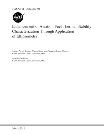
Enhancement of Aviation Fuel Thermal Stability CharacterizationThrough Application of EllipsometrySamuel Tucker Browne,1 Hubert Wong,2 and Cameron Branch Hinderer3National Aeronautics and Space AdministrationGlenn Research CenterCleveland, Ohio 44135Jennifer KlettlingerNational Aeronautics and Space AdministrationGlenn Research CenterCleveland, Ohio 44135AbstractASTM D3241/Jet Fuel Thermal Oxidation Tester (JFTOT) procedure, the standard method for testingthermal stability of conventional aviation turbine fuels is inherently limited due to the subjectivity in thecolor standard for tube deposit rating. Quantitative assessment of the physical characteristics of oxidativefuel deposits provides a more powerful method for comparing the thermal oxidation stabilitycharacteristics of fuels, especially in a research setting. We propose employing a SpectroscopicEllipsometer to determine the film thickness and profile of oxidative fuel deposits on JFTOT heater tubes.Using JP-8 aviation fuel and following a modified ASTM D3241 testing procedure, the capabilities of theEllipsometer will be demonstrated by measuring oxidative fuel deposit profiles for a range of differentdeposit characteristics. The testing completed in this report was supported by the NASA FundamentalAeronautics Subsonics Fixed Wing Project.1.0IntroductionSince the 1950’s, many people and organizations have relied on ASTM D3241 for thermal stabilityrating of conventional aviation fuels. Although this method has been universally utilized since itsinception, there have been numerous examples of people, academic discussions, and research thathighlight issues regarding subjectivity and accuracy of the current method, namely the visual ratingsystem. Despite a number of attempts to identify correlations between the color code and quantitativemeasurements, there has been little progress in this area overall. However, with an increasing emphasis onthe development of more economical and ecological technologies, it is increasingly evident that there is aneed for a more encompassing and advanced testing metric for quantifying the thermal stabilitycharacteristics of jet fuels. Improvements to the JFTOT visual rating system by way of a quantitative fueltesting metric may provide an improved tool for researchers and industry alike to facilitate advancementsin fuel system design and explore the potential benefits of future fuels.2.02.1BackgroundJet Fuel Thermal Oxidation Tester (JFTOT) ProcedureThe Jet Fuel Thermal Oxidation Tester, as designated by ASTM D3241, is a standardized test procedureused to assess the thermal stability of conventional aviation fuels. JFTOT rates jet fuels utilizing twometrics: first, differential pressure (dP) caused by particulate formation in the fluid must lie within a certain1NASA Glenn Research Center, summer intern from Cornell University.NASA Glenn Research Center, summer intern from University of California Berkeley.3NASA Glenn Research Center, summer intern from Villanova University.2NASA/TM—2012-2174041
Figure 1.—ADJD3241 standard color code for JFTOT.[Visual ratings ranging from 0 to 4 are given. Only2rate darkest spot of minimum size of 2.5 mm .]range; second, tube discoloration due to hydrocarbon deposits must not exceed a certain color on the visualrating scale. This paper concerns itself primarily with the tube discoloration. The highest temperature atwhich the fuel passes in both respects defines the respective break point. JFTOT involves aerated fuelflowing over a resistively heated tube at 260 C for 150 min to simulate jet fuel flow under engine operatingconditions (Ref. 1). Once the test is complete, the operator utilizes a standardized Visual Tube Rater (VTR)to determine the color rating. The VTR is an internally lit black box with three 30 W incandescent bulbs anda color chart that allows the operator to rate tube deposits on a scale of 0 to 4, which can be seen in Figure 1.A rating of 3 or less constitutes a passing score for the color test (Ref. 2).Numerous sources have found the standard visual rating method to be highly vulnerable to operatorsubjectivity (Refs. 3 and 4). Some studies have shown that reproducibility of results differed betweenoperators on the order of 6.5 C and up to a maximum of 15 C, which is considered unacceptable by manyin the research and fuel quality testing industries. The visual rating method fails to provide any informationregarding thickness or volume of the deposits. The bulk and depth of deposits can disturb fluid flow andeven cause blockages resulting in decreased engine performance. While the color of the engine componentsdoes not necessarily affect performance, fuel flow deposition and particulate formation plays an integralrole. Thus, integrating such a metric into JFTOT will strengthen the test rating’s value.It is also known that thicknesses in relation to the JFTOT color scale vary with heater tube material,fuel, and temperature. This implies that a comparison, for example, between the colors of depositionscreated by a conventional jet fuel and an alternative fuel would not be directly comparable. For thesereasons, it would be expected that different depositional patterns would manifest for each condition. Thisimplies that it may be more useful to know absolute magnitude of deposits, not just discoloration.In previously completed research, the thermal stability of Fischer-Tropsch (FT) fuel was compared toconventional Jet-A and various blends of Jet A and FT (Ref. 5). Fischer-Tropsch fuel was found to have asignificantly higher break point temperature than conventional Jet A, though limitations in the JFTOTprocedure inhibit the determination of the exact Fischer-Tropsch fuel break point temperature. It wasreasonable to assume that the break point temperature is higher than 380 C. It was also found that therewas no added thermal stability benefit of 50:50 blends in comparison to pure Jet A. Researchers foundFischer-Tropsch fuel to fail based on the color test well before the differential pressure metric, potentiallydue to the use of stainless steel in place of aluminum. This leaves questions in the researchers’ mindsspecifically on how accurately the JFTOT visual rating system depicts fuel fouling and its applicabilityacross metal compositions. The limitations in temperature range for aluminum tubes lead to the need for awider range of tube materials. It is important to recognize that other metals will have differentmechanisms in which they interact and discolor in the presence of jet fuel. Implementing a moreencompassing quantitative metric such as deposit thickness for thermal stability characterization willprovide a means to expand the gamut of fuels, temperature ranges, and metal compositions that JFTOTcan analyze. As non-petroleum based fuels progress in promise, both ecologically and economically, theability to rate such fuel is of utmost importance. Through improvements in JFTOT, such capabilities canbecome feasible.NASA/TM—2012-2174042
2.2EllipsometryIt was determined that ellipsometry may be a viable method of determining fuel deposit thicknesses.This was due to many factors, including the fact that the method is not dependent on knowing exactphysical properties of the film being examined. In fixed angle ellipsometry, light of known polarization isimpinged upon the surface and analyzed at a specified angle. At each interface between differentmaterials (i.e.: different layers on the JFTOT tubes), light is both reflected and transmitted, creatingmultiple reflected light waves. Electric field components parallel and perpendicular to the plane ofincidence are transmitted and reflected differently at each of these interfaces depending on the refractiveindex (n) of each material. Transmitted light diminishes in intensity within each layer depending on theextinction coefficient (k) of the material. The resulting reflected light waves differ from the impinginglight in both intensity and polarization and interference of these waves create elliptically polarized light.With spectroscopic ellipsometry, the intensity and phase change of the reflected light is measured over abroad spectrum of wavelengths. Mathematical models describing the depth and optical properties of thelayer as a function of wavelength are assumed and through an iterative process, unknown constants arevaried until calculated curves correlate well with measured curves. To obtain an accurate match, aquantitative estimate of the correlation between calculated and measured curves is generated using a typeof error function. The large number of data points provided by the broad spectrum of the spectroscopicellipsometer allows for highly accurate film thickness measurements with resolutions on the order of anangstrom (Ref. 6).3.03.1ExperimentJet Fuel Thermal Oxidation TesterJFTOT testing for this study was performed using a Hot Liquid Process Simulator (HLPS) modelHLPS-400 manufactured by Alcor. The HLPS machine, shown in Figure 2, is designed to simulate testingconditions as outlined in ASTM D3241 (Ref. 7). All operating conditions (i.e., fuel flow rate, test time,fuel system pressure etc.) are set in accordance with ASTM D3241 except experimental temperaturewhich is operator defined. JP-8 was chosen as the fuel for this study. Procedural details can be found inKlettlinger 2010 (Ref. 5). JFTOT testing was conducted at temperatures ranging between 255 and 275 Cto obtain a wide range of color ratings. As JFTOT designates testing at a temperature of 260 C forFigure 2.—Alcor HLPS-400 hot liquid. [Processsimulator graphic. Fuel flows form a reservoirpumped at a constant rate to flow fuel over the tubeat 3 mL/min. Three thermocouples provide pointtemperatures to roughly depict thermal profile.]NASA/TM—2012-2174043
conventional aviation fuels, additional tests were conducted at this condition. However, to obtain data thatwould express probable correlation between temperature and deposit thickness, a range of temperatureswas implemented into the test matrix. Following HLPS procedure, the heater tube specimen was visuallyrated in an Alcor Visual Tuberator, which corresponds to the rating method described in JFTOT protocol.3.2Ellipsometry MeasurementOnce samples have been created through the JFTOT procedure, physical characteristics, specificallyfilm thickness, can be attained using an ellipsometer. The sample can be mounted into a stand designed byHORIBA engineers to hold the JFTOT heater tube stationary. Ellipsometry was created on the pretense ofdetermining film thicknesses of a flat surface, so due to the curved surface of a cylindrical heater tube, therewere originally concerns that this would cause inaccuracies in readings. After testing these concerns werealleviated by finding variations to be insignificant in regards to either positioning or shape.After the sample tube was mounted inside the ellipsometer, the motorized stage which holds the tube inposition was manipulated so that the JFTOT tube was positioned correctly under the optical sensors. Thespot size was then set to the minimum size necessary to obtain optical measurements using the ellipsometer.To be consistent, a spot of 250 by 250 µm was selected and ensured to be evenly centered over the curvatureof the top of the tube. Once positioned here, the ellipsometer was used to obtain optical data on the fulllength of the tube—at 1 mm intervals. From this, raw information regarding the film’s optical propertieswas gathered and was ready to be fit to a dispersion model to determine the actual film thickness.The software supporting HORIBA’s ellipsometer allows for numerous different dispersion modelsand algorithms for fitting to be performed. First, under the assumption that the aluminum alloy JFTOTtube was nearly uniform throughout, a profile of non-uniformity in thickness and chemical composition inthe hydrocarbon deposits implied that a classical Lorentzian oscillator would not easily describe such asurface. After numerous iterations of absorbing disposition models, a “new amorphous” model derived byHoriba Jobin Yvon based on a Fourohi-Bloomer formulation was chosen. The fitting equation used todescribe this model can be seen below, and more information can be found in references (Ref. 8). Theequations below display the models for the coefficient of extinction, k, and refractive index, n. 2; for g f j gk 22 j j ; for g 0 n n (1) B j C j 2(2) 2jAlong with these equations, it is important to have general ranges and estimates for values of theunknowns that are being fit in the equations above. Table 1 list the approximate values for the unknownparameters contained in Equations (1) and (2). These unknowns describe different properties of theextinction coefficient; according to Horiba, ωg is the energy band gap, fj is related to the strength of theextinction coefficient peak, ωj is approximately the energy where the extinction coefficient is at amaximum, and Γj is the broadening term of the peak of absorption.MaterialTABLE 1.—OPTICAL PROPERTIES HYDROCARBONS.[Listing of approximate optical properties of general hydrocarbons.]n ωgfjωjHydrocarbonsNASA/TM—2012-217404 1.650 0.488 0.0844 3.443Γj 1.839
Figure 3.—Deposition model. [Aluminum substrate withtwo film deposit layers. Layer 1: hydrocarbon film.Layer 2: “roughness model”- air and hydrocarbon.]To assess the performance of the models, the difference between the theoretical and experimentalresults was calculated, squared, and averaged across the range of the model, resulting in a statisticalmetric called chi-squared (Χ2) that described the quality of fit. At first iterations, it was attempted tomodel the system as a simple aluminum substrate with a uniform layer of hydrocarbon deposits on top.This model resulted in Χ2 values on the order of 50 to 500 , which was deemed unacceptably high. Inseeking a Χ2 value on the order of 0.01 to 1.00, the model was modified to better represent the realisticdeposition patterns. After realizing the non-uniformity of the deposit thicknesses, it was desired to find away of adding a layer that could model this surface roughness. This was achieved by incorporating a layerthat represented a mixture of air and hydrocarbon material above a uniform hydrocarbon layer, see Figure3. This would allow measurements of not only deposit height of the second layer, but also the respectivepercentage of hydrocarbons present. From this, one could determine an average thickness of the secondlayer which could be added to the first layer to determine total hydrocarbon deposit thickness.Using this model, it was possible to achieve fits with chi squared values on the order of 0.05 to 0.20,which resulted in variations in coating thickness measurements on the order of 1 to 3 percent. Anamorphous dispersion model was used, allowing highly accurate determinations of thicknesses with chisquared values on the order of less than 1. From this, a relatively detailed profile for deposits could becreated. To determine more precise heights, readings were taken every 1.00 mm around the maximumrecorded heights from the first readings. Once one side was completed, the sample was rotated 90 andthen retested. This process was repeated until there was a profile and maximum height for every 90 . Themaximum height was then matched to the color rating taken from JFTOT testing. From this point,correlations between physical characteristics of the deposit thickness and colors could be observed.4.04.1Results/DiscussionModified JFTOTThe data collected from performing a number of runs in HLPS following the modified JFTOTprocedure as described in Section 3.1 was organized in Table 2 (For the complete set of experimental datacollected refer to Appendix A, Table 4). Note a minor software system error systematically displayedtemperature readouts 6 C actual experimental temperature; this is applicable across the entire range.Unless otherwise stated, temperatures have been altered to reflect true temperature.NASA/TM—2012-2174045
282011-6-27TABLE 2.—EXPERIMENTAL RESULTS[Test matrix showing different variables of successful JFTOT testing.Note temperatures have yet to be corrected for system error.]Fuel indexTest fileTubeRecordeddP,type temperature, mmHg CJP8-ASCR-2011-05-27 AL-275C-500AL275191JP8-ASCR-2011-05-27 AL-270C-500AL270196JP8-ASCR-2011-05-27 AL-265C-500AL265196JP8-ASCR-2011-05-27 AL-262C-500AL262189JP8-ASCR-2011-05-27 AL-260C-500AL2607JP8-ASCR-2011-05-27 AL-257C-500AL2571JP8-ASCR-2011-05-27 AL-255C-500AL2551JP8-ASCR-2011-05-27 AL-260C-500AL260192JP8-ASCR-2011-05-27 AL-260C-500AL260181JP8-ASCR-2011-05-27 AL-260C-500AL2607JP8-ASCR-2011-05-27 AL-260C-500AL2602DepositHeightPosition: -30 mmdPP/FColorratingColorP/FffffpppffPp 4 43, 4 32222221fffppppppPpExpected ThicknessProfile:0 mmClean Tube Section 30 mmDepositsFigure 4.—JFTOT heater tube and deposition pattern. [A JFTOT tube run at291 C that yielded a “3” on the color scale can be seen above. An expectedgeneral deposition pattern that may be seen through thickness measurement issuperimposed.]Runs executed at 266 C exhibited inconsistencies in differential pressure results. However, suchinconsistencies are taken into consideration by JFTOT procedure. As JFTOT dictates, runs are to beperformed at five degree intervals to definitively ascertain breakpoint. This accounts for potentialfluctuations in fuel performance as temperatures approach the actual breakpoint. In addition some runswere deemed invalid and not included in data analysis. Regardless of failure with respect to differentialpressure and visual rating, tests were considered invalid only when instrumentation/control systemmalfunctioned or the operator terminated the run prior to completion.4.2Angular Variation of Ellipsometer ProfilesUsing the ellipsometric procedure outlined in Section 3.3, a profile for a JFTOT tube was attained.This graph showed the heights of the deposits measured at positions. To better understand what isrepresented, a picture of a JFTOT tube is contained below. It is important to see the maximum thicknessof the color deposits, most importantly the dark areas on the tube. An example tube with depositionswhich were rated a “3” on the JFTOT color rating scale can be seen in Figure 4. Also included is aprediction of the expected thickness profile, showing the relatively low deposit height in the clean sectionof the tube, followed by the bumpy rounded deposition profile.NASA/TM—2012-2174046
Figure 5.—Multi-angle film deposit profile of single aluminum heater tube.[This figure shows the relative profile of deposition along a JFTOT tube runat 291 C that yielded a “ 4” on the color test. The fuel type used for thiscase was JP8.]It was expected that for the profile of the tube that along the discolored parts there would be themaximum deposition and along the parts that appeared clear, there would be relatively little deposition.This was verified as can be seen in the data seen above in Figure 5. The lower relative distances from thecenter, between 0 to 5 mm represent the clean tube portion. These had maximum depositions on theorder of 20 to 30 nm. Positions between 5 to 20 mm represent the visibly discolored area on the tube. Itwas expected that there would be a gradually rising rounded profile. What was found, in reality, was arising profile that was not well-rounded and appeared to have irregular dips and peaks. This implied aneed to validate results through another method, which is described in Section 4.3. It was verified,though, that the peak deposit heights were located in the darkest areas on the tube. Another encouragingresult was that the maximum heights of depositions at different angles around tubes were similar, on theorder of 15 percent variations. This allows for one to take measurements on only one side and know withrelative certainty that the maximum height is close to the maximum height along the whole tube.4.3Validation Techniques for Ellipsometer ResultsIt was determined that a secondary method for determining film thickness would be used in order tovalidate the ellipsometer’s results. Two readily accessible methods, interferometric microscopy and laserextensometry, were first explored. Interferometric microscopy only examines the surface profile of asmall area on the surface of the sample, so the only way to obtain the thickness of the film is to create astep from the film to bare aluminum tube by removing some of the film and then measuring the height ofthe film layer. However, because of the surface irregularities of the tube it is hard to differentiate betweenthe film and the bare aluminum at the step. This means thickness measurements made using this methodare unreliable and inconclusive, and therefore interferometric microscopy would not be a viable methodfor determining film thickness.Laser extensometry measures the width of an object placed between a laser and sensor; in the case ofthe JFTOT heater tubes the width corresponds to the diameter of the tube. Thus, determining the thicknessof the hydrocarbon deposits using laser extensometry involves measuring the heater tube before and afterJFTOT testing and then calculating the difference. The accuracy of this calculation requires thatmeasurements be made in the exact same angular positions on the tube to avoid inaccuracies caused bynon-uniform circumferential deposition and/or heater tube surface irregularities.NASA/TM—2012-2174047
While the laser extensometer used has a claimed resolution of 50 nm (Ref. 9), initial resultsdemonstrate relatively large variations in the overall heater tube profile as well as pronounced surfaceroughness. In Figure 6, a 200 nm thick line, representing a reasonable film thickness value, issuperimposed upon a sample tube profile to exhibit the necessary resolution the instrument must becapable of achieving. While some of these surface features seemed to be reproducible, even smallchanges in angular position yielded much different profiles meaning differences calculated between preand post test laser extensometer profiles may not represent actual film thickness. This demonstrates laserextensometry as an inadequate method for determining film thickness.Scanning Electron Microscopy (SEM) was considered as another option to validate ellipsometer filmthickness measurements. SEM provides highly magnified images which in our case can be used tomeasure the film height directly. Originally, we had intended to use a small diamond scribe to scratch thesurface of the tube, image the area at different angles with the SEM, and then calculate the depthaccordingly using the known angular orientations. However, after viewing the film surface on the heatertube, bare areas were present along the tube providing reference surfaces by which to measure filmthickness as illustrated in Figure 7. These measurements were then corrected for the angular orientation ofthe area imaged. Film thickness at several points along a heater tube was measured using this method and8000Δ Diameter nce Along Tube (cm)Figure 6.—Variations in JFTOT tube diameter. [A comparison betweenthe tube diameter (red) and a 200 nm thick line (blue) demonstratesthe considerable surface irregularities present on the tube.]Figure 7.—SEM image of hydrocarbon film onaluminum. [The lighter area in the bottom of thefigure represents the aluminum substrate while thehydrocarbon deposits are visible in the upperportion. Using the SEM the thicknesses of thedeposits could be measured.]NASA/TM—2012-2174048
the results were compared to the ellipsometer measurements. Figure 8 illustrates the film thicknessprofiles measured using SEM compared to 3 film thickness profiles measured using the ellipsometer.From this plot we see that the maximum heights from all three profiles agree well with one another. SEManalysis yielded a maximum thickness value of 233.3 nm compared to 233.8, 202.4, and 218 nm for the0, 90, and –90 measurements respectively. These values correspond to percentage deviations frommeasured SEM maximum deposit thickness of 0.0, 13.2, and 6.6 percent respectively. The reasonablecorrelation between results from both methods suggests that the ellipsometer measurements arerepresentative of actual deposit thicknesses.Figure 9 shows the chemical characterization of tube deposits using scanning electron microscopyenergy-dispersive x-ray (SEM-EDX) spectroscopy. These two images show the results at two differentlocations along the tube surface. On the left, position 0, the film shows very little carbon deposition and ahigh quantity of aluminum from the tube surface. This indicates that position 0 is expected to be a verythin film. On the right, position B, the film is analyzed to have a high quantity of carbon as well as anincreased deposition of oxygen. Visual observation is consistent with the SEM analysis as point 1 isdarker in color.Figure 8.—SEM versus spectroscopic ellipsometer. [Deposit thicknessmeasurements from SEM are superimposed onto previous ellipsometrymeasurements. Thes
The resulting reflected light waves differ from the impinging light in both intensity and polarization and interference of these waves create elliptically polarized light. With spectroscopic ellipsometry, the intensity and phase change o