Transcription
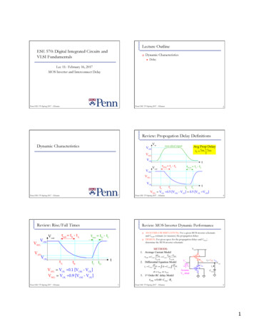
Lecture OutlineESE 570: Digital Integrated Circuits andVLSI Fundamentals!Dynamic Characteristics"DelayLec 11: February 16, 2017MOS Inverter and Interconnect DelayPenn ESE 570 Spring 2017 – KhannaPenn ESE 570 Spring 2017 – Khanna2Review: Propogation Delay DefinitionsDynamic CharacteristicsPenn ESE 570 Spring 2017 – Khanna3Review: Rise/Fall Times4Penn ESE 570 Spring 2017 – KhannaReview: MOS Inverter Dynamic Performance!!ANALYSIS (OR SIMULATION): For a given MOS inverter schematicand Cload, estimate (or measure) the propagation delaysDESIGN: For given specs for the propagation delays and Cload*,determine the MOS inverter schematicMETHODS:1. Average Current Modelτ PHL CloadΔVHLV V50% Cload OHI avg,HLI avg,HL2. Differential Equation ModeliC CloaddVout dt dt C loaddVoutiCdt τ PHL or τ PLH3. 1st Order RC delay ModelAssumeVin idealτ PHL 0.69 Cload RnPenn ESE 570 Spring 2017 – Khanna5Penn ESE 570 Spring 2017 – Khanna61
Case 1: Vin Abruptly Rises - τPHLMethod 2linearsaturationt0#t1Differential Equation ModelVDD VT 0 nτ PHL Cload VDDt1#t50%" 1 % 'dVout Cload# iDn &τ PHL VDD /2VDD VT 0 nV out V DD V T0n" 1 % 'dVout# iDn &" 2(VDD VT 0n ) VDD 2 %2CloadVT 0nCload ln 'kn (VDD VT 0n )2 kn (VDD VT 0n ) #VDD 2&Rnτ PHL Cload Penn ESE 570 Spring 2017 – Khanna8Penn ESE 570 Spring 2017 – KhannaCase 1: Vin Abruptly Rises - τPHLτ PHL Cload ) 2V# 2(VDD VT 0n ) &,1T 0n ln % 1(. kn (VDD VT 0n ) * (VDD VT 0n ) VDD 2'-Differential Model Approximation) 2V# 2(VDD VT 0n ) &,1T 0n ln % 1(. kn (VDD VT 0n ) * (VDD VT 0n ) VDD 2'-τ PHL Cload ) 2V# 2(VDD VT 0n ) &,1T 0n ln % 1(. kn (VDD VT 0n ) * (VDD VT 0n ) VDD 2'-linearsaturationRecall from static CMOS Inverter:VT 0 n Vth 1(VDD VT 0 p )kRVDD VT 0 n" V VT 0 p Vth %kR DD'# Vth VT 0 n&1kR1 t0#t1τ PHL Cload V2DDτ PHL Cload VDESIGN: (1) Vth kR; (2) τPHL kn; (3) kR & kn kpDD# 1 &%%((dVout iDn,sat 'τ PHL 9Penn ESE 570 Spring 2017 – KhannaDifferential Model Approximationt0#t1τ PHL Cloadlinear!" 1 %VDD /2 VDD VT 0 n # i '&dVoutDnApproximate by assuming in velocity saturation:VDD /2τ PHL Cload VDDΔ is less than 10%τ PHLVdsat #&%( Cload%(dVout% v C W *V V Vdsat - (% sat OX , DD T 0n( 2 ./ ' CloadVDD RnCload#V &2vsat COX W %VDD VT 0n dsat ( 2 ' Penn ESE 570 Spring 2017 – Khanna# 1 &%%((dVout iDn,vsat ' Penn ESE 570 Spring 2017 – Khanna!t1#t50%VDD VT 0 n " 1 % VDD # i '&dVout CloadDn VDD /2VDD VT 0 n" 1 % 'dVout# iDn & VDD /2VDD#&%( Cload%(dVoutk% n (VDD VT 0n )2 ( 2'CloadVDD RnCloadkn (VDD VT 0n )2Δ is less than 10%10Example 1:) 2V# 2(VDD VT 0n ) &,1T 0n ln % 1(. kn (VDD VT 0n ) * (VDD VT 0n ) VDD 2'-saturation" 1 % 'dVout Cload# iDn &Approximate by assuming in saturation:VDD /2τ PHL Cload t1#t50%LvsatµnConsider a CMOS inverter with Cload 1pF andVDD 5V. The nMOS transistor has VT0n 1V andkn 625uA/V2.Assume Vin is an ideal step pulse with instant rise/fall times. Calculate the delay time necessary for theinverter output to fall from its initial value of 5V to2.5V.τ PHL Cload ) 2V# 2(VDD VT 0n ) &,1T 0n ln % 1(. kn (VDD VT 0n ) * (VDD VT 0n ) VDD 2'-VDD /2VDD11Penn ESE 570 Spring 2017 – Khanna122
Example 1:!!Example 1:Consider a CMOS inverter with Cload 1pF andVDD 5V. The nMOS transistor has VT0n 1V andkn 625uA/V2.Assume Vin is an ideal step pulse with instant rise/fall times. Calculate the delay time necessary for theinverter output to fall from its initial value of 5V to2.5V.τ PHL Cload τ PHL Cload ) 2V# 2(VDD VT 0n ) &,1T 0n ln % 1(. kn (VDD VT 0n ) * (VDD VT 0n ) VDD 2'-τ PHL 1 10 12 τ PHL 0.52nsApproximate by assuming in saturation:τ PHL ) 2V# 2(VDD VT 0n ) &,1T 0n ln % 1(. kn (VDD VT 0n ) * (VDD VT 0n ) VDD 2'-τ PHL 1 10 12 ) 2# 2(5 1) &,1 ln % 1(. 2.5'(625 10 6 )(5 1) * (5 1)CloadVDD RnCloadkn (VDD VT 0n )2) 2# 2(5 1) &,1 ln % 1(. 2.5'(625 10 6 )(5 1) * (5 1)τ PHL 0.52nsPenn ESE 570 Spring 2017 – Khanna13Example 1:τ PHL Cload 14Penn ESE 570 Spring 2017 – KhannaExample 2:) 2V# 2(VDD VT 0n ) &,1T 0n ln % 1(. kn (VDD VT 0n ) * (VDD VT 0n ) VDD 2'-τ PHL 1 10 12 !) 2# 2(5 1) &,1 ln % 1(. 2.5'(625 10 6 )(5 1) * (5 1)!τ PHL 0.52nsApproximate by assuming in saturation:τ PHL CloadVDD RnCloadkn (VDD VT 0n )2τ PHL 1 10 12 (5) 0.5ns625 10 6 (5 1)2Consider a CMOS inverter with Cload 1pF andVDD 5V. The nMOS transistor has VT0n 1V,k’n 20uA/V2, and W/L 10.Use the average current method to calculate the falltime. Assume VOH VDD, and VOL 0V.Usefull equations:τ fall CloadΔV90% 10%V V Cload 90% 10%I avg,90% 10%I avg,90% 10%Δ 3%15Penn ESE 570 Spring 2017 – KhannaExample 2:!!k 'n W2(VGS VT 0 n )2 Lk' W n(2 (VGS VT 0 n ) VDS V 2DS )2 LI D,sat I D,linPenn ESE 570 Spring 2017 – Khanna16Example 2:Consider a CMOS inverter with Cload 1pF andVDD 5V. The nMOS transistor has VT0n 1V,k’n 20uA/V2, and W/L 10.Use the average current method to calculate the falltime. Assume VOH VDD, and VOL 0V.!!Consider a CMOS inverter with Cload 1pF andVDD 5V. The nMOS transistor has VT0n 1V,k’n 20uA/V2, and W/L 10.Use the average current method to calculate the falltime. Assume VOH VDD, and VOL 0V.I avg, fall 0.988mA1[ic (Vin VOH ,Vout V90% ) ic (Vin VOH ,Vout V10% )]21I avg, fall [ic (Vin 5V,Vout 4.5V ) ic (Vin 5V,Vout 0.5V )]2%1 "k ' Wk' W22I avg, fall n(Vin VT 0 n ) n ( 2 (Vin VT 0 n ) Vout V out)'&2# 2 L2 L 6 6%1 " 20 1020 102I avg, fall (10) ( 5 1) (10) ( 2 ( 5 1) (0.5) (0.5)2 )'2#22&I avg, fall τ fall CloadΔV90% 10%V V Cload 90% 10%I avg,90% 10%I avg,90% 10%τ fall 1 10 124.5 0.5 4ns0.988 10 3I avg, fall 0.988mAPenn ESE 570 Spring 2017 – Khanna17Penn ESE 570 Spring 2017 – Khanna183
Example 2:Example 2:Consider a CMOS inverter with Cload 1pF andVDD 5V. The nMOS transistor has VT0n 1V,k’n 20uA/V2, and W/L 10.Use the differential equation method to calculate thefall time. Assume VOH VDD, and VOL 0V.!!!Usefull equations:iC CloaddVout dtid ,satConsider a CMOS inverter with Cload 1pF andVDD 5V. The nMOS transistor has VT0n 1V,k’n 20uA/V2, and W/L 10.Use the differential equation method to calculate thefall time. Assume VOH VDD, and VOL 0V.!dVout1 W2 k 'n (Vin VT 0n )dt2L2Cloaddt dVout2k 'n (W L ) (VDD VT 0n )iC Cload dt C load1 W k 'nV V2L GS T 0n(dVoutiC)22 1 10 12dt 1 Wid ,lin k 'n2(VGS VT 0n )VDS V 2DS2L()20 10 6 (10 ) ( 5 1)t tsat dt t t90%Penn ESE 570 Spring 2017 – Khanna19Example 2:!dVout1 W2 k 'n ( 2(Vin VT 0n )Vout V out)dt2L2Cloaddt dV2k 'n (W L ) ( 2(VDD VT 0n )Vout V out) outiC Cloadt t10% dt t tsatt t10% dt t tsatt t10% dt t tsat2Cloadk 'n (W L )20Vout 0.5 Vout 4(2(VDDConsider a CMOS inverter with Cload 1pF and VDD 5V.The nMOS transistor has VT0n 1V, kn 20uA/V2, and W/L 10.Use the differential equation method to calculate the falltime. Assume VOH VDD, and VOL 0V.!!t90% tsat 0.313nst t10%1dV2 VT 0n )Vout V out) out dt t tsatt t10% 21t0#t1!1 ## &&dVout Cload" iDp %linearV50% VT 0 pt tsatVout 0.5 Vout 4(2(VDD1dV2 VT 0n )Vout V out) out 2(V V ) V10% 'Cload1 ln & in T 0n)k 'n (W L ) Vin VT 0n %V10%(dt 2(5 1) 0.5 '1 10 121 ln &) 3.39ns(20 10 6 (10 ) 5 1 %0.5saturationt0#t1!1 ## &&dVout" iDp % VT 0 pτ PLH Cload 0) 2 V # 2(VDD VT 0 p ) &,1T0p ln % 1(. k p (VDD VT 0 p ) * (VDD VT 0 p )VDD 2 '.-Avg method: 4ns22τ PLH Cload !1 ## &&dVout Cload" iDp %lineart1#t50% V50% VT 0 p!1 ## &&dVout" iDp %) 2 V # 2(VDD VT 0 p ) &,1T0p ln % 1(. k p (VDD VT 0 p ) * (VDD VT 0 p )VDD 2 '.-τ PLH Penn ESE 570 Spring 2017 – Khannat90% t10% 3.39ns 3.7nsCase 2: Vin Abruptly Falls - τPLHt1#t50% 2Cloadk 'n (W L )dt t tsatCase 2: Vin Abruptly Falls - τPLHsaturationt90% tsat 0.313nsdVout1 W2 k 'n ( 2(Vin VT 0n )Vout V out)dt2L2Cloaddt dV2k 'n (W L ) ( 2(VDD VT 0n )Vout V out) outiC Cload 2(5 1) 0.5 '1 10 121 ln &) 3.39ns(20 10 6 (10 ) 5 1 %0.5τ PLH Cload 6.25 10 10 dVout 0.313nsPenn ESE 570 Spring 2017 – Khannat t10% VT 0 p Vout 4.5 2(V V ) V10% 'Cload1 ln & in T 0n)k 'n (W L ) Vin VT 0n %V10%(τ PLH Cload 0dVout 6.25 10 10 dVoutExample 2:Consider a CMOS inverter with Cload 1pF and VDD 5V.The nMOS transistor has VT0n 1V, kn 20uA/V2, and W/L 10.Use the differential equation method to calculate the falltime. Assume VOH VDD, and VOL 0V.!2Vout 4023Penn ESE 570 Spring 2017 – KhannaCloadVDDk p (VDD VT 0 p )2RpRpCload244
Differential Equation ModelReview: MOS Inverter Dynamic Performance!!ANALYSIS (OR SIMULATION): For a given MOS inverter schematicand Cload, estimate (or measure) the propagation delaysDESIGN: For given specs for the propagation delays and Cload*,determine the MOS inverter schematicτ PHL Cload τ PLH Cload METHODS:1. Average Current Modelτ PHL CloadΔVHLV V50% Cload OHI avg,HLI avg,HL) 2V# 2(VDD VT 0n ) &,1T 0n ln % 1(. kn (VDD VT 0n ) * (VDD VT 0n ) VDD 2'-) 2 V # 2(VDD VT 0 p ) &,1T0p ln % 1(. k p (VDD VT 0 p ) * (VDD VT 0 p )VDD 2 '.-CONDITIONS for Balanced CMOS Propagation Delays, i.e.2. Differential Equation ModeliC CloaddVout dt dt C loaddVoutiCdt τ PHL or τ PLH3. 1st Order RC delay Model#AssumeVin ideal! W µn ! W #& #&" L % p µ p " L %nτ PHL 0.69 Cload Rn25Penn ESE 570 Spring 2017 – KhannaDelay Observationsτ PHL Cload τ PLH Cload 26Penn ESE 570 Spring 2017 – KhannaDelay Design Equations) 2V# 2(VDD VT 0n ) &,1T 0n ln % 1(. kn (VDD VT 0n ) * (VDD VT 0n ) VDD 2'-τ PHL Cload ) 2V# 2(VDD VT 0n ) &,1T 0n ln % 1(. kn (VDD VT 0n ) * (VDD VT 0n ) VDD 2'-) 2 V # 2(VDD VT 0 p ) &,1T0p ln % 1(. k p (VDD VT 0 p ) * (VDD VT 0 p )VDD 2 '.-τ PLH Cload 27Penn ESE 570 Spring 2017 – KhannaApproximation: Delay Design Equationsτ PHL ) 2 V # 2(VDD VT 0 p ) &,1T0p ln % 1(. k p (VDD VT 0 p ) * (VDD VT 0 p )VDD 2 '.-28Penn ESE 570 Spring 2017 – KhannaDesign for Delays with More Realistic Model for CloadCload i i Cdbn Cdbp Cint CgbCloadVDDkn (VDD VT 0n )2!W CloadVDD# & " L %n τ PHL µ nCox (VDD VT 0n )2τ PLH CloadVDDk p (VDD VT 0 p )2!W CloadVDD# & " L % p τ PLH µ pCox (VDD VT 0 p )2Penn ESE 570 Spring 2017 – Khannai iCload29Penn ESE 570 Spring 2017 – KhannaCdbn(Wn) Cdbp(Wp) Cint Cgb305
Design for Delays with More Realistic Model for CloadDesign for Delays with More Realistic Model for Cloadτ PHL Cload ) 2 V # 2(VDD VT 0 p ) &,1T0p ln % 1(. k p (VDD VT 0 p ) * (VDD VT 0 p )VDD 2 '.-τ PLH Cload τ PHL Γ n) 2V# 2(VDD VT 0n ) &,1T 0n ln % 1(. kn (VDD VT 0n ) * (VDD VT 0n ) VDD 2'-CloadWnandτ PHL Γ pCloadWpCdbn (Wn) [Wn (Y xj)] Cj0n Keqn (Wn 2Y) Cjswn Keqn(sw)Cdbp (Wp) [Wp (Y xj)] Cj0p Keqp (Wp 2Y) Cjswp Keqp(sw)Cload α0 αnWn αpWpα0 2YCjswnKeqn 2YCjswpKeqp Cint Cgbαn (Y xj)Cj0nKeqn CjswnKeqnαp (Y xj)Cj0pKeqp CjswpKeqp31Design for Delays with More Realistic Model for Cloadτ PHL Cload τ PLHDesign for Delays with More Realistic Model for Cload) 2V# 2(VDD VT 0n ) &,1T 0n ln % 1(. kn (VDD VT 0n ) * (VDD VT 0n ) VDD 2'-τ PHL Γ n) 2 V # 2(VDD VT 0 p ) &,1T0p Cload ln % 1(. k p (VDD VT 0 p ) * (VDD VT 0 p )VDD 2 '.-τ PHL Γ nCloadWnandτ PHL Γ pτ PHL Γ pCloadWpCload α0 αnWn αpWpCload α0 (αnWn/Wp)Wp αpWpCload α0 [αn/R αp]WpCloadWp1 µWwhere R Wp/Wn constant (Recall: Vth p p when Lp Ln)kRconst.33Penn ESE 570 Spring 2017 – KhannaDesign for Delays with More Realistic Model for CloadτPLH ΓpCloadWnCload α0 αnWn αpWpCload α0 αnWn (αpWp/Wn)WnCload α0 [αn αpR]WnΓn and ΓP are set largely by process parameters and VDDτPHL Γn α0 [αn αpR]WnWn32Penn ESE 570 Spring 2017 – KhannaτPHL Γn α0 [αn αpR]WnWnτPLH Γpµ nWnα0 [αn/R αp]WpWpPenn ESE 570 Spring 2017 – Khanna34Design for Delays with More Realistic Model for Cloadα0 [αn/R αp]WpWpwhere R (constant) aspect ratio Wp/WnHence increasing Wn and Wp will have diminishing influence on τPHL andτPLH as they become large, i.e.τPHL limit τPHL Γn [αn αp R]τPLH limit τPLH Γp [αn/R αp]Wn largeabsoluteminimumdelaysWp largePenn ESE 570 Spring 2017 – Khanna35Penn ESE 570 Spring 2017 – Khanna366
Taking Into Account Non-Ideal Input Waveform1st Order RC Delay Modelideal Vinnon-ideal VinVout to ideal VinVout to non-ideal Vin37Penn ESE 570 Spring 2017 – KhannaPenn ESE 570 Spring 2017 – Khanna1st Order RC Delay Modelsτ PHL 0.69 Cload Rn!1st Order RC Delay Models!Cload Cdbn Cdbp Cint CgbEquivalent circuits used for MOS transistors"Ideal switch “effective” ON resistance load capacitance""""""Define unit resistance, Ru: “effective” ON resistance of transistor with min lengthand W Wu (usually min width)nMOS has “effective” ON resistance Rn Run/κn and capacitances κnCd, κnCgpMOS has “effective” ON resistance Rp Rup/κp and capacitances κpCd, κpCg"""" scale factors κn 1 and κp 1, i.e. Wn κnWun, Wp κpWupCgb Cg and Cdb Csb Cd for the unit n/pMOS transistors""""ExampleUnitTransistors39V1 (t) VDD (1 e1st Order RC Delay Model -τPLH t/R pCload)V1 (t) VDD (1 eVDDStep Source140Penn ESE 570 Spring 2017 – Khanna1st Order RC Delay Model -τPLH0Capacitance directly proportional to gate width (W) # C W*CConductance directly proportional to gate width (W) # G W*GResistance is inversely proportional to gate width (W) # R R/WCapacitance directly proportional to gate width (W) # C W*CConductance directly proportional to gate width (W) # G W*GResistance is inversely proportional to gate width (W) # R R/WPenn ESE 570 Spring 2017 – Khanna0Define unit resistance, Ru: “effective” ON resistance of transistor with min lengthand W Wu (usually min width)nMOS has “effective” ON resistance Rn Run/κn and capacitances κnCd, κnCgpMOS has “effective” ON resistance Rp Rup/κp and capacitances κpCd, κpCg" scale factors κn 1 and κp 1, i.e. Wn κnWun, Wp κpWupCgb Cg and Cdb Csb Cd for the unit n/pMOS transistorsNMOS and pMOS transistor at minimum gate length (L)"NMOS and pMOS transistor at minimum gate length (L)"Ideal switch “effective” ON resistance load capacitance"Equivalent circuits used for MOS transistors"38VDDRpStep SourceV1(t)1t0CloadV1(0) 00V50% RpV1(t)tV1(0) 0Cload t/R pCload)VDD τ/R C VDD (1 e PLH p load )21 τ PLH /RpCload e21τln PLH2RpCloadτ PLH ln(2)RpCload 0.69RpCloadPenn ESE 570 Spring 2017 – Khanna41Penn ESE 570 Spring 2017 – Khanna427
1st Order RC Delay Model -τPLH1st Order RC Delay Model -τPHLV1 (t) VDD (1 eVDDV50% Step SourceRp100V1(t)tCloadV1(0) 0 t/R pCloadV1 (t) VDD e t/RnCload)VDDVDD τ/R C VDD (1 e PLH p load )21 τ PLH /RpCload e21τln PLH2RpCloadRn100VDD VDD e τ PHL /RnCload21 τ PHL /RnCload e21τln PHL2RnCloadV50% Step SourceV1(t)tCloadV1(0) VDDτ PHL ln(2)RnCload 0.69RnCloadτ PLH ln(2)RpCload 0.69RpCload(0 # 50%)NOTE: τ RpCload(0 # 63%)Penn ESE 570 Spring 2017 – Khanna43nMOS 1st Order RC Delay Model – Equiv. Rn44Penn ESE 570 Spring 2017 – KhannapMOS 1st Order RC Delay Model – Equiv. RpsκnCdRn Run/κnκnCgκnCdκpCdRp Rup/κpWhere Wn κnWunON/OFFκnON/OFFκpκn 1, usually κn 1κpCgκpCddτ PHL Rn CloadVDD 0.69RnCloadkn (VDD VT 0n )2τ PLH VDD Lun0.69µ nCoxκ nWun (VDD VT 0n )2Rp 45Penn ESE 570 Spring 2017 – Khanna1st Order Delay Model -τPHLVDD VDDκpCd1,κpVDDκpA1VDDYn1,κκp p1,κp12RnuR/κppVDDκpCd21CdRp Rpu/κp Rn46Penn ESE 570 Spring 2017 – KhannaVDD VDDκpCd1,κpVDDVDDnκp CgκpA1VDDYn1,κκp p1,κp1nCg2RnuR/κppVDDκpCd21Cs Cd CdiffVDDnκpCgYRnCdnCgwhere Wn Wunit κn 1, Rn RunWp κpWunitPenn ESE 570 Spring 2017 – KhannaVDD Lup0.69µ pCoxκ pWp (VDD VT 0 p )2Cs Cd Cdiffwhere Wn Wunit κn 1, Rn Runκp µn/ µp 2CloadVDD 0.69RpCloadk p (VDD VT 0n )21st Order Delay Model -τPHLYRnWhere Wp κpWupκp 1, usually κp µn/µpWp κpWunitCdκp µn/ µp 247Rp Rpu/κp RnPenn ESE 570 Spring 2017 – KhannaCd488
1st Order Delay Model -τPHLVDD VDDReff,HL Rn RnuReff,LH Rp Rpu/κp RnκpCdRp!!VDDVDDVDDκpCdnκpCgκpCdYRnReview: MOS Inverter Dynamic PerformanceCdRn/Rn nVDDnκpCgYκCnCdnCgANALYSIS (OR SIMULATION): For a given MOS inverter schematicand Cload, estimate (or measure) the propagation delaysDESIGN: For given specs for the propagation delays and Cload*,determine the MOS inverter schematicMETHODS:1. Average Current Modelτ PHL CloadnCκnCgΔVHLV V50% Cload OHI avg,HLI avg,HL2. Differential Equation ModelCload (1 κp)(Cd nCg)iC CloaddVout dt dt C loaddVoutiCdt τ PHL or τ PLHCd3. 1st Order RC delay Modelτ PHL 0.69RnCload 0.69Rn (1 κ p )(Cd nCg )AssumeVin idealτ PHL 0.69 Cload Rnτ PHL τ PLH49Penn ESE 570 Spring 2017 – KhannaRing Oscillator50Penn ESE 570 Spring 2017 – KhannaRing Oscillator051Penn ESE 570 Spring 2017 – KhannaRing Oscillator10152Penn ESE 570 Spring 2017 – KhannaRing Oscillator SYM INVSYM INV τPHL τPLH τptf τPHL2 τPHL1 τPHL3τPLH3 ττPLH11111 τp T 6τ p 2nτ p2nfPLH2SYM INV τPHL τPLHPenn ESE 570 Spring 2017 – Khanna53Penn ESE 570 Spring 2017 – Khanna549
Idea!AdminPropogation Delay"Average Current ModelDifferential Equation Model"1st Order Model""!HW 5 due Thursday, 3/2"Posted after classApproximationsPenn ESE 570 Spring 2017 – Khanna55Penn ESE 570 Spring 2017 – Khanna5610
sat µ n Penn ESE 570 Spring 2017 – Khanna Example 1: !Consider a CMOS inverter with C load 1pF and V DD 5V. The nMOS transistor has V T0n 1V and k n 625uA/V2. ! Assume V in is an ideal step pulse with instant ris