Transcription
REC-OCE-70-37Edward J. TrautDivision of DesignOffice of Chief EngineerBureau of ReclamationAugust 1970
BM-230 (6 70)Bureau of Reclamation1.TECHNICAL REPORT STANDARD TIT E PAGEREPORT NO.3.RECIPIENT'S CATALOG NO.5.REPORT DATE6.PERFORMING ORGANIZATION CODE8.PERFORMING ORGANIZATIONREPORT NO .REC-OCE-70-374.TITLE AND SUBTITLEHigh Head Gate Seal Studies7.AUTHOR(S)August 1970Edward J. Traut9.PERFORMING ORGANIZATION NAME AND ADDRESSDivision of DesignOffice of Chief EngineerBureau of ReclamationDenver, Colorado 8022512.10.WORK UNIT NO.11.CONTRACT OR GRANT NO .13.TYPE OF REPORT AND PERIODCOVERED14.SPONSORING AGENCY CODESPONSORING AGENCY NAME AND ADDRESS15.SUPPLEMENTARY NOTES16.ABSTRACTStudies were continued on rubber seals to determine the most suitableseal for use on wheel and roller-mounted gates operating under very highheads. The major problem encountered during the closing cycle under unbalanced pressure conditions is the pinching of the seal bulb betweenthe seal clamp and seal seat. Seven factors affecting this pinchingwere varied in attempts to find the optimum seal assembly capable ofwithstanding high pressure heads. Ten double-stem seal variations usingcombinations of stem thickness, fluorocarbon cladding, and rubber compositions were tested at heads up to 6oo ft (182.88 m). Tests were conducted in a special test rig accommodating 12-1/8-in.-long (30.798-cm)seal specimens. Tests consisted of measuring the seal bulb extensionand photographing and observing general behavior of the seal under loadduring simulated opening and closing cycles of the gate.17.KEY WORDS AND DOCUMENT ANALYSISa.DESCRIPTORS--/b.IDENTIFIERS·-/*gate seals/ *high pressure gates/ high pressure/ seals(stoppers)/ test procedures/ *laboratory tests/ physical properties/hydraulic gates and valves/ friction/ test facilities*high head/ fluorocarbons/ friction coefficient (mech)/test resultsc18 .COSATI F i eld / GroupDISTRIBUTION STATEMENT19 .SECURITY CLASS 21.( THIS REPOR T)NO . OF PAGE18Ava i lable f r om the Clear i nghouse for Federal Sc i entif i c and TechnicalUNCLASSIFIEDInformation , Nat i onal Bureau of Standards, U .S. Department of Commerce, r-2- 0-. ;;.;S E.;;.c""u R.;;.l ,,.T.;.Y.;C, ;;;L;.;:;A;.,S,.,,S .:-22"".--,,p--R-IC--E-------tSpringfield , V i rgin i a 22 151.( THIS PAGE)UNCLASS I FIED 3 .00
REC-OCE-70-3 7HIGH HEAD GATE SEAL STUDIES .,.!byEdward J. TrautAugust 1970Mechanical BranchDivision of DesignOffice of Chief EngineerDenver, ColoradoUNITED STATES DEPARTMENT OF THE INTERIORWalter J. HickelSecretaryBUREAU OF RECLAMATIONEllis L. ArmstrongCommissioner
ACKNOWLEDGMENTThis study, successor to Report No. Hyd-582 (1968) by R. D.Mohrbacher, was initiated by D. B. Mountjoy of the Mechanical Branchand was conducted in the Hydraulics Branch under the supervision ofW. E. Wagner, Head, Structures and Equipment Section. Photographywas by W. M. Batts, Office Services Branch.
CONTENTSPagePurposeConclusionsRecommended UsesApplications . . .Specific InformationTest Facility . . .122Description of Seal SpecimensTest Procedure3. . . . . . .3Comparison of Seal Performance3LIST OF TABLESTable12Summary of data obtained on gate seal specimensDescription of seal specimens. . . . . . .67LIST OF FIGURESFigure1234567891011Seal assembliesSeal designs .Typical gate installationTest facility. . . .Section through high head gate seal test rigSpecimen 4A being tested at 600 feet (182.88 meters) of headSpecimen 2A being tested at 600 feet (182.88 meters) of headSpecimen 58 after testing to 450 feet (137 .16 meters)Specimen 3A after testing to 600 feet (182.88 meters)Comparison of permanent set of 11/16-inch (1.74-cm) stem sealsComparison of permanent set on 1/2-inch (1.27-cm)and 11/16-inch (1.74-cm) stem seals. . . . . . . . .89101112131415161718
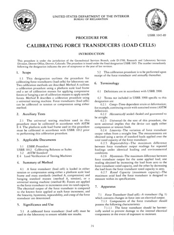
PURPOSESeveral types of clamp-on seals for high-head gateswere tested to obtain comparative operational data.Earlier tests 1 had indicated that the clamp-on typewere the best supported seals and that the extent offluorocarbon cladding had an effect on performance.For this study additional samples with variouscombinations of fluorocarbon and rubber compositionwith variations of seal assemblies were tested tocompare relative performances. The seal best suited for600-foot (182.88-meter) head was sought.CONCLUSIONS1. Using thicker stems on the seals decreased the bulbextension at high heads.2. Reducing the pressure-slot area behind the sealappeared to reduce the amount of seal-bulb extension.(See Figure 1B.)3. Using a new clamp, modified to increase theclamping action on the seal stem, appeared to decreasethe bulb extension at all heads. (See Figure 1C.) Thisseal assembly would have to be installed with a"built-in" seal interference to insure proper sealing atlow heads.4. The fluorocarbon cap bonded to the bulb and stemsdecreased the bulb extension. However, a small"permanent set" was present in the seals after beingsubjected to very high pressures. This "permanent set"was more pronounced when the fluorocarbon capcovered both the stems. A fluorocarbon cap on thebulb and the pressure side of the stem would avoid this"permanent set," with little loss of the seal assemblyeffectiveness at very-high heads.5. An appropriate seal would have to be chosen foreach installation according to the design head as noneof the seals are ideal for all heads.Recommended UsesAll clamp-on type seals.For heads up to 150 feet (45.72 m) use a seal with a1/2-inch (1.27-cm) stem and a fluorocarbon capbonded to the bulb only.For heads of 150 feet (45.72 m) to 300 feet (91.44 m),use a seal with a 1/2-inch (1.27-cm) stem and afluorocarbon cap bonded to the bulb and both stems.1For heads of 300 feet (91.44 m) to 450 feet (137.16m), use a seal with an 11/16-inch (1.74-cm) stem and afluorocarbon cap bonded to the bulb and both stems.For heads of 450 feet ( 137 .16 m) and above, use a sealwith an 11/16-inch (1.74-cm) stem and a fluorocarboncap bonded to the bulb and both stems installed with aclamp which limits movement of the seal stem over asmall pressure slot.The following conclusions were established earlier 1 andwere used as a basis for these tests:The clamp-9n-type seals tested were superior tobolt-through design seals in two respects: (a) Thebulb extension and resulting pinching tendencyduring the closing cycle of the gate was reduced,and (b) the clamp-on-type seals showed lesstendency to vibrate when the bulb was in theproximity of the seal seat.A brass or fluorocarbon cap bonded to the bulbsignificantly reduced the tendency for the bulb tobe pinched between the clamp and the seal seat.The fluorocarbon cap was superior to the brass capbecause of its lower coefficient of friction andgreater flexibility.Extending the fluorocarbon cap to cover the lower(high-pressure side) stem of the seal reduced thetendency to disbond between the cap from therubber, reduced the bulb extension, and reduced thetendency for vibration during the gate-operatingcycle.Extending the fluorocarbon cap to cover both stemsfurther reduced the bulb extension and thetendency of the cap to disbond from the rubberduring the gate-operating cycle.Seal failure by pinching occurred more readily asthe speed of the gate closure was increased.Seal specimens appeared to pinch more as theclamp-to-seat clearance was reduced, when closedwith the same bulb extension.APPLICATIONSThese studies produced data and general informationto aid the designer in choosing a suitable seal for aparticular application. The choice will depend almostentirely upon the hydraulic head acting on the gate.Mohrbacher, R. D., "High-head Gate Seal Studies," Bureau of Reclamation Report No. Hyd-582, 1968.
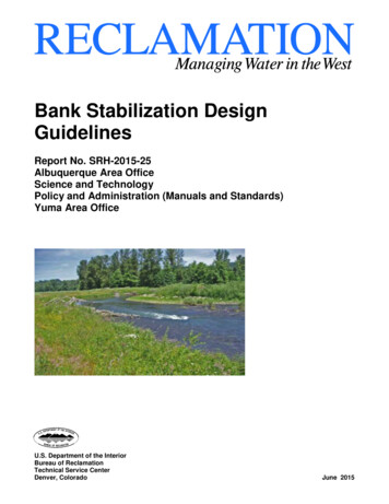
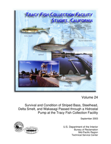
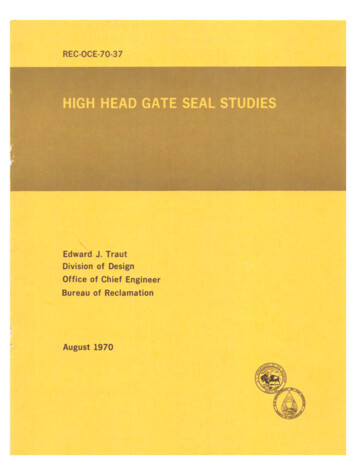
produces a bulb extension of the seal before the sealcontacts the seal seat. As the bulb moves onto the seat,the extension of the bulb causes it to be pinchedbetween the clamp and the seal seat. No pinchingproblem exists on the side seals because of continuouscontact with the seal seats.Table 1 gives bulb-extension data and the heads atwhich seal failure, if any, occurred.With this information an adequate and economical sealdesign may be chosen for a specific application.SPECIFIC INFORMATIONSeal failure due to pinching was found to be a functionof the following factors:All the seals tested were of the double-stem designs asshown in Figure 2. These seals are used on wheel- androller-mounted gates which are used primarily as guardgates in penstocks, outlet works, and spillways ininstallations similar to that shown in Figure 3.1. Amount of seal-bulb extension.2. Deformability of the bulb.3. Clamp-to-seat clearance.It is possible to use metal-to-metal sealing on relativelysmall gate installations. However, as the gate sizeincreases it becomes impossible to maintain properalinement of the metal-sealing surfaces. For this reasonrubber seals are clamped to the gate in a manner thatallows flexing of the seal to compensate forinaccuracies in gate fabrication and seal-seat alinementwhen large gates are used.4. Coefficient of friction between the bulb and theseal seat.5. Strength of bond between the cladding and therubber.6. Rate of gate closure.On earlier low-head gate installations, rubber seals witha cross-sectional shape similar to that of a music notewere commonly used. When gates with higher headscame into use, the music-note seals no longer gavesatisfactory service and a double-stem,bolt-through-type seal was developed and installed. Asheads on gates continued to increase it was necessaryto develop a seal which would perform satisfactorilyunder these higher heads. The double-stem, clamp-onseal shown in Figure 2 was developed and proved tohave definite advantages over the bolt-through-typeseal for high-head sealing applications. Differentvariations of the double-stem, clamp-on seal weredeveloped and tested to determine the seal mostsuitable for very-high heads. This report gives theresults of these tests.7. Slope of the surface which forces the extendedbulb of the seal inward to the seal seat.In this test program, Factors 1 and 2 above were variedin an attempt to find the most-suitable seal assembly.The next four factors had been varied in previous testsbut not in these tests. The retraction slope on the sealseat could not be changed readily, so Factor 7 was notvaried in any of the tests performed. The slope of thetest-rig seal seat was purposely made greater than theseal seats normally used in a gate installation to providea more-critical condition than actually encountered ina typical gate installation.The seals used in these tests were supplied, at no costto the Government, by a commercial firm. The sealshad the same shape as those used in recent Bureau ofReclamation installations, but utilized differentcombinations of fluorocarbon coverings, stemthicknesses, and rubber composition. The fluorocarbonused on these seals is a green opaque material whichhas proven satisfactory in previous seal tests.Gates with rubber seals are generally operated underbalanced water-pressure conditions, but they must alsobe suitable for emergency closure at unbalancedpressure conditions: full reservoir head on theupstream side of the gate leaf and approximatelyatmospheric pressure on the downstream side of thegate. During emergency closure the seals are subjectedto the greatest stresses.TEST FACILITYA typical seal assembly has a pressure groove behindthe seal which provides a hydrostatic pressure thatforces the seal bulb against the seat when the gate isunder pressure. During the emergency closing cycle theunbalanced pressure acting on the top and bottom sealsThe seal tests were conducted in a specialBureau-designed test rig, shown in Figures 4 and 5. Therig has a fixed seal assembly and a movable seal seatoperated by a hydraulic cylinder mounted on top ofthe rig. Although the seat is fixed and the seal moves in2
- -- - - - - - - - - - - - - - - - - - - - - - -the prototype, this arrangement provided the samerelative seal-seat motion, and had the advantage ofkeeping the seal in view through plastic windowsthroughout the gate test cycle. The hydraulic cylinderwas actuated by a variable displacement pump locatedadjacent to the test rig.Plastic windows on each side of the test rig allowedphotographing the seal behavior. Water was pumpedthrough an 8-inch (20.32-cm) pipe into the bottom ofthe test rig at a maximum head of 612 feet (186.54 m).Flow past the seal was upward and was deflected to thebottom rear of the test rig where it was discharged.Pressure was applied to a pressure slot at the back sideof the seal by a 1-inch (2.54-cm) pipe connection fromthe 8-inch (20.32-cm) supply line. Shims behind theseal base provided a means of varying the clamp-to-seatclearance. The seal assembly was removable from theupstream side of the test rig to facilitate changing ofthe seal specimens.Description of Seal SpecimensThe seal specimens were prototype-size sections,12-1/8 inches (30.798 cm) long. (See Figure 2 for sealdimensions.) Twelve specimens of ten different designsof rubber seals were tested in the tests described above.A description of the cladding and the modules of therubber used on each specimen is given in Table 2.Physical properties for all specimens referred to asregular modulus rubber: (As tested and reported by themanufacturer).Shore A Durometer Hardness 71Tensile strength 4,191 psi (294.65 kg/cm 2 )Elongation at break 600 percentModulus of elasticity at 300 percentelongation 1,422 psi (99.97 kg/cm2)Physical properties for all specimens referred to ashigh-modulus rubber: (As tested and reported by themanufacturer).Shore A Durometer hardness 70Tensile strength 3,809 psi (267.79 kg/cm 2 )Elongation at break 500 percentModulus of elasticity at 300 percentelongation 1,808 psi (127 .11 kg/cm 2 )TEST PROCEDUREData taken in this study included:1. Measurement of the seal-bulb extension in ahorizontal direction from its initial position whensubjected to a given head of water.These measurements were taken at increments of 25to 100 feet (7.62 to 30.48 meters) of head up toseal failure or to a maximum head set for thespecific seal tested if failure was not desired. Themaximum head used in any of the tests was 600 feet(182.88 m). These measurements were taken byalining a grid of lines, spaced at 0.10-inch(2.54-mm) intervals on both sides of a 2-inch-thickpiece of transparent plastic, with a similar grid oflines on the test-rig window. As all of the specimenshad a 0.030-inch (0.762-mm) thick fluorocarboncap on the bulb, it was possible to estimate the sealextension to the nearest hundredth of an inch(0.254 mm).2. General observations of seal performance duringgate operations.3. Motion pictures of seal performance duringtest-rig operation.4. Still photographs of a few seals at selected headswith the seal. under load or sometimes not loaded.5. Visual examination and photographs of sealsafter removal from test rig.The clamp-to-seat clearance was varied from 7/32 inch· (0.56 cm) to 15/32 inch (1.19 cm) at different timesduring the testing of the different seal specimens. Somespecimens were tested at more than one clearance. Thesize of the pressure slot was also reduced during thetesting program and all seals subsequently testedreflected this change (Figure 18). A modification wasalso made to the seal clamp (Figure 1C) during thetesting program in an effort to determine the effect of·seal clamping.Comparisons of Seal Per:formanceAll of the following specimens discussed in thiscomparison are tabulated in .Table 1.Fluorocarbon specifications: 0.030 inch (0.762 mm)thick; tensile strength 2,000 psi (140.61 kg/cm 2 )minimum; elongation 250 percent (minimum).3All seal specimens tested were of the clamp-on designhaving a green fluorocarbon cap bonded to the bulband sometimes one or both of the stems.
Specimen No. 58 had a 1/2-inch (1.27-cm) stem withfluorocarbon bonded to the bulb and the lower stem(pressure side) and was made of regular-modulusrubber. This seal specimen was tested with a 3/8-inch(0.95-cm) clamp to seat clearance to show that a1/2-inch (1.27-cm) stem seal was unable to sustain highheads (over 400 feet [121.92 m]) with an unmodifiedseal assembly. (Figure 1A.) When tested, the seal bulbwas pinched enough to crease the fluorocarbon capduring the gate-closing cycle at 450 feet (137 .16 m) ofhead. (Figure 8.) Testing was stopped at this point. (Itshould be noted that this crease in the fluorocarboncap would not prevent the seal from sealing.) When theseal specimen was removed from the test rig, a slightpermanent set was observed on the fluorocarbon stemside of the bulb. (Figure 8.)At this point in the testing program the width of thepressure slot behind the seal was reduced from 3 to 2inches (7.62 to 5.08 cm) by filling it with 2-1/2-inch(1.27-cm) square bars.Specimen No. 78 had a 1/2-inch (1.27-cm) stem withfluorocarbon bonded to the bulb and lower stem(pressure side) and was made of high-modulus rubber.This specimen, about the same as 58, was tested at3/8-inch (0.95-cm) clamp-to-seat clearance to checkthe effectiveness of the reduced pressure slot inreducing the amount of bulb extension. The sealspecimen was tested to 400 feet (121.92 m) of headwith no perceivable damage. It appeared that thesmaller pressure slot helped to reduce the bulbextension on this specimen. A very-slight permanentset was noticed on the side with fluorocarbon on thestem.Specimen No. 38 had an 11/16-inch (1.74-cm) stemwith a fluorocarbon cap bonded to the bulb and thelower stem (pressure side) and was made ofhigh-modulus rubber. This specimen was tested at7/32-inch (0.56-cm), clamp-to-seat clearance to give acomparison with the 1/2-inch (1.27-cm) stem sealstested in the previous report (1I. The seal performedwell up to 500 feet (152.40 ml of head without anypermanent damage. The test was stopped at 550 feet(167.64 ml of head as it appeared the seal would bedamaged if allowed to close. Upon removal from thetest rig no permanent damage was observed. Nopermanent set was observed.Specimen No. 18 had an 11 /16-inch (1.74-cm) stemwith fluorocarbon bonded to the bulb and lower stem(pressure side) and was made of regular-modulusrubber. This specimen was tested at 15/32-inch(1.19-cm) clamp-to-seat clearance. It was tested to 400feet (121.92 ml of head with no damage to the sealand a nominal amount of bulb extension. The testswere stopped at 400 feet (121.92 m) of head toprevent any damage to the seal so that it could beretested upon modification of the clamps. Nopermanent set was observed.Specimen No. 28 had an 11/16-inch (1.74-cm) stemwith fluorocarbon bonded to the bulb and both stemsand was made of regular-modulus rubber. Thisspecimen was tested at 3/8-inch (0.95-cm)clamp-to-seat clearance. The seal performed very wellunder up to and including 600 feet (182.88 m) ofhead. Upon removal from the test rig no permanentdamage to the specimen was observed, however therewas a slight indentation on the upper side (nonpressureside) of the fluorocarbon cap where it contacted theclamp while under pressure. A slight permanent set wasnoticed directly under the bulb.At this point in the testing program the seal assemblywas further revised by soldering a 1/8-inch (0.32-cm)diameter brass rod to the underside of the seal clamp atthe point where it contacts the seal stem at the base ofthe bulb. (See Figure 1C.) This created a clampingaction at that point. The change was made in anattempt to reduce the amount of bulb ext nsion,especially at high heads. (Fabrication of a seal clamp inthis manner would not be recommended as this shouldbe accomplished by gradually building it up to apoint.)Specimen No. 48 had an 11/16-inch (1.74-cm) stemwith fluorocarbon bonded to the bulb and both stemsand was made of high-modulus rubber. This specimenwas tested at 3/8-inch (0.95-cm) clamp-to-seatclearance. Specimen No. 48 performed almost exactlythe same as 28 including the indentation in thefluorocarbon on the upper side (nonpressure side) ofbulb. A slight permanent set was also observed at thebulb. (See Figure 118.)Specimen No. 18 was retested at this point to give adirect check of the effectiveness of the modified clampin reducing the amount of bulb extension at highheads. This specimen was retested at 15/32-inch(1.19-cm) clamp-to-seat clearance as it was in theprevious test without the modified clamps. The sealspecimen performed well up to and including 600 feet(182.88 m) of head with no apparent damage to theseal specimen. The modified clamps appeared to reducethe amount of bulb extension slightly at low heads and4
reduced the bulb extension significantly at higherheads. Upon removal from the test rig the sealspecimen appeared to be in perfect condition exceptfor a very slight permanent set on the side withfluorocarbon on the stem. (Figure 108.)fluorocarbon cap along the upper (nonpressure) side ofthe bulb and a slight disbonding of the fluorocarbonwas noted on the upper (nonpressure) side of thefluorocarbon cap. (It should be pointed out that thecrease in the fluorocarbon would not prevent the sealfrom sealing.) No permanent set was observed.Specimen No. 1A had an 11/16-inch (1.74-cm) stemwith fluorocarbon bonded to the bulb only and wasmade of regular-modulus rubber. This specimen wastested at 3/8-inch (0.95-cm) clamp-to-seat clearance. Itperformed adequately up to 600 feet (182.88 m) ofhead, except for the fact that the fluorocarbon capbroke loose at lower edge of the bulb at 550 feet(167.64 m) of head. Upon removal of the specimenfrom the test rig it was found that the fluorocarboncap had come loose only at the edge and could not beconsidered a real failure but rather a spot that was notbonded properly. No permanent set was observed.Specimen No. 4A had an 11/16-inch (1.74-cm) stemwith fluorocarbon bonded to the bulb and both stemsand was made of high-modulus rubber. This specimenwas tested at· 15/32-inch (1.19-cm) clamp-to-seatclearance and its performance was almost the same asthat of Specimen No. 2A. A permanent set wasobserved at the bulb.Specimen No. 6A had a 1/2-inch (1.27-cm) stem withfluorocarbon bonded to the bulb and both stems andwas made of regular-modulus rubber. This specimenwas tested at 3/8-inch (0.95-cm) clamp-to-seatclearance and it performed well up to 500 feet (152.40m) of head. There was no visible damage to the sealspecimen when it was removed from the test rig. Theimproved performance of a 1/2-inch (1.27-cm) stemseal appeared to be due to the modified clamp. andreduced pressure slot. A very-pronounced l)erinanentset was present directly at the bulb.Specimen No. 2A had an 11/16-inch (1.74-cm) stemwith fluorocarbon bonded to the bulb and both stemsand was made of regular-modulus rubber. Thisspecimen was · tested at 3/8-inch (0.95-cm)clamp-to-seat clearance and performed adequately upto 600 feet (182.88 m) of head with no extensivepinching of the bulb. When removed from the test rigthe seal was in good condition, except that it had aslight permanent set directly under the bulb. (FigureSpecimen No. SA had a 1/2-inch (1.27-cm) stem withfluorocarbon bonded to the bulb and both stems andwas made of high-modulus rubber. This specimen wastested at 3/8-inch (0.96-cm) clamp-to-seat clearance- and it performed without damage up to 600 feet(182.88 m) of head. This seal specimen also had novisible damage when removed from the test rig. Theimproved performance of the seal specimen, testing a1/2-inch (1.27-cm) stem seal to 600 feet (182.88 m) ofhead with no damage, appeared to be due to themodified clamp and reduced pressure slot. Avery-pronounced permanent set was present at thebulb. (Figure 11A.)10A.)Specimen No. 3A had an 11/16-inch (1.74-cm) stemwith fluorocarbon bonded to the bulb only and wasmade of high-modulus rubber. This specimen wastested at 15/32-inch (1.19-cm) clamp-to-seat clearance.The general performance appeared to be about thesame as Specimen No. 1A with the exception that thebulb extended slightly more. The increased bulbextension appeared to be caused by the largerclamp-to-seat clearance. Upon removal from the test rig(see Figure 9) it was found to have a ridge in the5
Table 1SUMMARY OF DATA OBTAINED ON GATE SEAL SPECIMENSB lb extension (inches)·Head -(feet of water)Specimen No.068100Remarks150 200 250 300 350 400 450 500 550 600Wide pressure slot (see Figure 1A)5B (1/2 inch-F.C. on bulband lower stem, reg. mod.)3B (11/16inch-F.C. on bulband lower stem, high mod.)2B (11/16inch-F.C. on bulband both stems, reg. mod.)4B (11/16 inch-F.C. on bulband both stems, high mod.)00.10 0.15 0.16 0.20 0.25 0.30 0.40 0.44 0.6500.09 0.10 0.11 0.12 0.20 0.26 0.32 0.37 0.42 0.6200.02 0.03 0.04 0.05 0.07 0.12 0.13 0.14 0.23 0.26 0.34 0.39.Seal pinched at 450 feet3/8-inch clamp clearanceToo far extruded at 500 feet7/32-inch clamp clearance3/8-inch clamp clearance00.013/8-inch clamp clearance0.05 0.06 0.06 0.10 0.14 0.20 0.23 0.29 0.32 0.40Pressure slot reduced (see Figure 1B)7B (1/2 inch-F.C. on bulband lower stem, high mod.)1B (11/16 inch-F.C. on bulband lower stem, reg. mod.)00.08 0.10 0.10 0.13 0.16 0.17 0.25 0.2900.08 0.09 0.11 0.13 0.19 0.24 0.29 0.33Trend established3/8-inch clamp clearanceTrend established15/32-inch clamp clearanceModified clamp and pressure slot reduced (see Figure 1C)1B (retest)1A (11/16 inch-F.C. on bulbonly, reg. mod.2A (11 /16 inch-F .C. on bulband both stems, reg. mod.3A (11/16 inch-F.C. on bulbonly, high mod.)4A (11/16 inch-F.C. on bulband both stems, high mod.)6A (1/2 inch-F.C. on bulband both stems reg. mod.)BA (1/2 inch-F.C. on bulband both stems, high mod.)000.05 0.08 0.12 0.15 0.18 0.23 0.26 0.31 0.31 0.33 0.36 0.390.05 0.070.24 0.29 0.34 0.41 0.50 0.56 0.570.1315/32-inch clamp clearance3/8-inch clamp clearance00.01 0.050.090.15 0.19 0.25 0.30 0.34 0.43 0.503/8-inch clamp clearance00.05 0.100.170.26 0.35 0.37 0.44 0.55 0.63 0.690O.Q1 0.050.120.16 0.20 0.24 0.27 0.37Seal pinched at 600 feet15/32-inch clamp clearance15/32-inch clamp clearance00.03 0.040.110.14 0.27 0.33 0.34 0.3600.02 0.040.080.13 0.17 0.23 0.32 0.37 0.47 0.540.45Trend established3/8-inch clamp clearance3/8-inch clamp clearance·-
Table 2DESCRIPTION OF SEAL SPECIMENS(All seals clamp-on-type with green fluorocarbon cladding)SpecimennumberStemthicknessCladdingon bulbCladdingon lowerstem1A182A,283A384A,48586A7811/16 inch11/16 inch11/16 inch11116inch11/16 inch11116inch112inch1/2 inch1/2 inch1/2 YesYesYesYesSA7Claddingon igh
O. UNMODIFIED SEAL ASSEMBLYFLOWsideIb. SEAL ASSEMBLY WITH REDUCED PRESSURE SLOTC. SEAL ASSEMBLY WITH REDUCED PRESSURE SLOTAND MODIFIED CLAMPSNOTE:All seal assemblies are shown with aFigure 1. Seal assemblies.8½- inchstem.
Fluorocarbon cladding onbulb and both stems. - - FLOW ---------11-16-INCHSTEM THICKNESSSEALFluorocarbon cladding onbulb and pressure stem.FLOW 511---------------58---------------it -INCHSTEM THICKNESSSEALFigure 2. Seal designs (see Table 2 for extent of fluorocarbon cladding on specific seals).9
""· s. E.\.- :;:s;:.--o40.o-----o:::M iiiE . \ . s s'1i-J\ .S.oo-- pelistoc \0 1 Q\O.M \ n . '1-1.s.E,\. 5 G0 '2 . , 0 0figure 3. ,v p i c a\ gate10insta\\ation.
A. Overall view of test facility-showing water pump, controls, andgate seal test rig. Photo PX-D-60628B. Gate seal test rig. Photo PX-D-57233 NAFigure 4. Test facility.11
HydraulicCylinderTo HydraulicPump,. -H- --lf--------- tt'l-::::;;:::---PI as ticWindows----nnrr-Non- pressureside of sealSealClamp-to-seatclear an c e------t, :t--.---H-Pressure sideof sealSeatFrom High ---. · --Head Pumpa" PipeFigure 5. Section through high head gate seal test rig.12
CLAMP- S EAT C L EARANCEHE A D Goo/ FEETTE-STHIGHS A MPLE4A /HEAD GATE SEAL TESTSl!1wA. Seal bulbPX-D-67478)extendedduringC L A M P - S E A T C L E AR AN C EHED600, FE E TS A MPLEHIGH4Aclosing3/e,cycle.0IHEAD GATE SEAL)B. Gate in closed position. Photo PX-D-67477Figure 6. High head gate seal studies.13Photo
CLAMP - S E AT -CHEE AR AN C E319 D 600 1 FE ETT ES TS A MP LE2A. 'HIGHHEAD GA TE SEAL TESTSA. Seal bulbPX-D-67476extendedduringCL A MP - S E AT CL E AR A NCEclosingcycle.Photo319 HEAD 600,FEETTESTS AMPLEH I GHHEAD GATE SEAL2A I B. Gate in closed position. Photo PX-D-67475Figure 7. Specimen 2A being tested at 600 feet of head.14
Photo PX-0-67484Photo PX-O-67486Figure 8. Specimen 5B after testing to 450 feet (137.16 m).15
Photo PX-D-67480Photo PX-D-67485Figure 9. Specimen 3A after testing to 600 feet (182.88 m).16
A. Fluorocarbon cap on both stems. Photo PX-D-67479B. Fluorocarbon cap on pressure side stem only. Photo PX-D-67482Figure 10. Comparison of permanent set of 11/16-inch stem seals.17
A. 1/2-inch stem seal. Photo PX-D-67481B. 11/16-inch stem seal. Photo PX-D-6748:tFigure 11. Comparison of permanent set on 1/2- and 11 /16-inch stem seals.18
7-1750 (1-70)Bureau or ReclamationCONVERSION FACTORS--BRITISH TO METRlC UNITS OF MEASUREMENTThe following conversion factors a:lopted by the Bureau of Reclamation are those published by the American Society forTestin-;i- and Materials (ASTM Metric Practice Guide, E 380-68) except that additional factors (*) commonly u.sed inthe Bureau have been a:lded. Further discussion of definitions of quan ities and units is given in the ASTM MetricPractice Guide,The metric units and conversion factors adopted by the ASTM are based on the "International System of Units" (designatedSI for Systeme International d'Unites), fixed by the International Committee for Weights and Measures; this system isalso known as the Giorgi or MKSA (meter-kilogram (mass)-second-ampere) system. This system has been adopted bythe International Organization for Standardization in ISO Recommendation R-31.The metric technical unit of force is the kilogram-force; this is the force which1 when applied to a body having amass of 1 kg, gives it a
1. Amount of seal-bulb extension. 2. Deformability of the bulb. 3. Clamp-to-seat clearance. 4. Coefficient of friction between the bulb and the seal seat. 5. Strength of bond between the cladding and rubber. 6. Rate of gate closure. 7. Slope of the surface which fo