Transcription
Semi-Automatically Mapping StructuredSources into the Semantic Web?Craig A. Knoblock1 , Pedro Szekely1 , Jose Luis Ambite1 , Aman Goel1 ,Shubham Gupta1 , Kristina Lerman1 , Maria Muslea1 , Mohsen Taheriyan1 , andParag Mallick21University of Southern CaliforniaInformation Sciences Institute and Department of Computer ,lerman,mariam,mohsen}@isi.edu2Stanford UniversityDepartment of Radiologyparagm@stanford.eduAbstract. Linked data continues to grow at a rapid rate, but a limitation of a lot of the data that is being published is the lack of a semanticdescription. There are tools, such as D2R, that allow a user to quicklyconvert a database into RDF, but these tools do not provide a way toeasily map the data into an existing ontology. This paper presents a semiautomatic approach to map structured sources to ontologies in order tobuild semantic descriptions (source models). Since the precise mappingis sometimes ambiguous, we also provide a graphical user interface thatallows a user to interactively refine the models. The resulting source models can then be used to convert data into RDF with respect to a givenontology or to define a SPARQL end point that can be queried withrespect to an ontology. We evaluated the overall approach on a varietyof sources and show that it can be used to quickly build source modelswith minimal user interaction.1IntroductionThe set of sources in the Linked Data cloud continues to grow rapidly. Many ofthese sources are published directly from existing databases using tools such asD2R [8], which makes it easy to convert relational databases into RDF. This conversion process uses the structure of the data as it is organized in the database,which may not be the most useful structure of the information in RDF. Buteither way, there is often no explicit semantic description of the contents of a?This research is based upon work supported in part by the Intelligence AdvancedResearch Projects Activity (IARPA) via Air Force Research Laboratory (AFRL)contract number FA8650-10-C-7058. The views and conclusions contained hereinare those of the authors and should not be interpreted as necessarily representingthe official policies or endorsements, either expressed or implied, of IARPA, AFRL,or the U.S. Government.
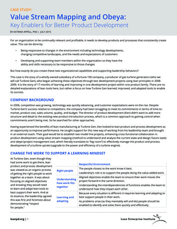
2Knoblock et al.source and it requires a significant effort if one wants to do more than simplyconvert a database into RDF. The result of the ease with which one can publishdata into the Linked Data cloud is that there is lots of data published in RDFand remarkably little in the way of semantic descriptions of much of this data.In this paper, we present an approach to semi-automatically building sourcemodels that define the contents of a data source in terms of a given ontology. Theidea behind our approach is to bring the semantics into the conversion processso that the process of converting a data source produces a source model. Thismodel can then be used to generate RDF triples that are linked to an ontologyand to provide a SPARQL end point that converts the data on the fly into RDFwith respect to a given ontology. Users can define their own ontology or bring inan existing ontology that may already have been used to describe other relateddata sources. The advantage of this approach is that it allows the source to betransformed in the process of creating the RDF triples, which makes it possibleto generate RDF triples with respect to a specific domain ontology.The conversion to RDF is a critical step in publishing sources into the LinkedData cloud and this work makes it possible to convert sources into RDF with theunderlying semantics made explicit. There are other systems, such as R2R [7]and W3C’s R2RML [9], that define languages for specifying mappings betweensources, but none of this work provides support for defining these mappings. Thispaper describes work that is part of our larger effort on developing techniquesfor performing data-integration tasks by example [23]. The integrated system isavailable as an open-source tool called Karma3 .2Motivating ExampleThe bioinformatics community has produced a growing collection of databaseswith vast amounts of data about diseases, drugs, proteins, genes, etc. Nomenclatures and terminologies proliferate and significant efforts have been undertaken to integrate these sources. One example is the Semantic MediaWiki LinkedData Extension (SMW-LDE) [5], designed to support unified querying, navigation, and visualization through a large collection of neurogenomics-relevant datasources. This effort focused on integrating information from the Allen Brain Atlas (ABA) with standard neuroscience data sources. Their goal was to “bringABA, Uniprot, KEGG Pathway, PharmGKB and Linking Open Drug Data [16]data sets together in order to solve the challenge of finding drugs that targetelements within a disease pathway, but are not yet used to treat the disease.”We use the same scenario to illustrate and evaluate our contributions, comparing our results to the published SMW-LDE results (see Figure 1). We uselogical rules to formally define the mapping between data sources and an ontology. Specifically, we use global-local-as-view (GLAV) rules [13] commonly usedin data integration [15] and data exchange [3] (i.e., rules whose antecedent andconsequent are conjunctive formulas). The rule antecedent is the source Group/Web-Karma-Public
Semi-Automatically Mapping Structured Sources into the Semantic WebThing: subclass: object propertyTop: data eggGeneIduniprotIdPharmGKBPathways(Accession Id, Name, Drug Id, Drug Name,Gene Id, Gene Name, Disease Id, Disease Name) Pathway(uri(Accession Id)) ˆ name(uri(Pathway Id), Name) ˆinvolves(uri(Pathway Id), uri(Gene Id)) ˆisTargetedBy (uri(Pathway Id), uri(Drug Id)) ˆisDisruptedBy (uri(Pathway Id), uri(Disease Id)) ˆGene(uri(Gene Id)) ˆ geneSymbol(uri(Gene Id), Gene Name) ˆDrug(uri(Drug Id)) ˆ name(uri(Drug Id), Drug Name) ˆDisease(uri(Disease Id)) ˆ name(uri(Disease Id), Disease Name)Fig. 1. The ontology used in the SMW-LDE study, one of the KEGG Pathway sourcesused, and the source model that defines the mapping of this source to the ontology.that defines the columns in the data source. The rule consequent specifies howthe source data elements are defined using the ontology terms. For example, thefirst term, Pathway(uri(Accession Id)) specifies that the values in the Accession Id column are mapped to the Pathway class, and that these values shouldbe used to construct the URIs when the source description is used to generate RDF. The second term, name( uri( Accession Id), Name) specifies that thevalues in the Accession Id are related to the values in the Name column usingthe name property.The task in the SMW-LDE scenario is to define source models for 10 datasources. Writing these source models by hand, or the equivalent R2R rules islaborious and requires significant expertise. In the next sections we describehow our system can generate source models automatically and how it enablesusers to intervene to resolve ambiguities.
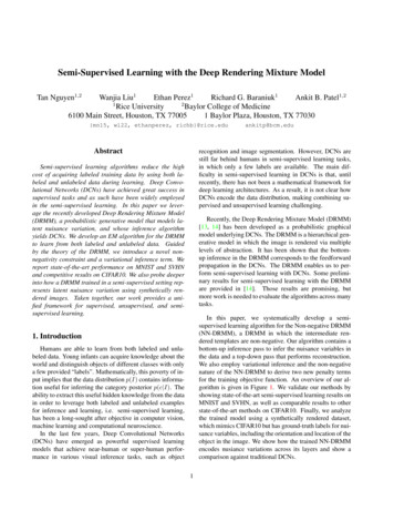
4Knoblock et FormalSpecificationSourceModelLearned Semantic TypesFig. 2. The Karma process to model structured sources.3Modeling Structured SourcesFigure 2 illustrates our approach for modeling data sources. The inputs to theprocess are an OWL ontology, the collection of data sources that the user wantsto map to the ontology, and a database of semantic types that the system haslearned to recognize based on prior use of the tool. The main output is the modelthat specifies, for each source, the mapping between the source and the ontology.A secondary output is a refined database of semantic types, updated during theprocess to incorporate semantic types learned using the data contained in thesources being mapped.As shown in Figure 2, the modeling process consists of four main steps. Thefirst step, Assign Semantic Types, involves mapping each column of a source toa node in the ontology. This is a user-guided process where the system assignstypes automatically based on the data values in each column and a set of learnedprobabilistic models constructed from assignments done in prior sessions. If thesemantic type assigned by the system is incorrect, the user can select from amenu the correct node in the graph. The system learns from this assignmentand records the learned assignment in its database. The second step, ConstructGraph, involves constructing a graph that defines the space of all possible mappings between the source and the ontology. At a high level, the nodes in thegraph represent classes in the ontology, and the edges represent properties thatrelate these classes. The mapping from the ontology to the graph is not one-toone given that, for example, several columns may contain instances of the sameclass (Section 3.2). The third step, Refine Source Model, updates the graph torefine the model based on user input. The graph is constructed so that the mapping between the source and the ontology can be computed using a Steiner treealgorithm (Section 3.3). The final fourth step, Generate Formal Specification,generates a formal specification of the source model from the Steiner tree computed in the prior step (Section 3.5). An example of this formal specificationappears in the bottom part of Figure 1.In general, it is not always possible to automatically compute the desiredmapping between a source and an ontology since there may not be enough information in the source to determine the mapping. So, the automated process
Semi-Automatically Mapping Structured Sources into the Semantic Web5computes the most succinct mapping, and the user interface allows the user toguide the process towards the desired interpretation (Section 3.4).3.1Inferring the Semantic TypesSemantic types characterize the type of data that appears in a column of data.For example, in the table shown in Figure 1, the first column contains PharmGKB identifiers of pathways, the second one contains names of pathways, etc.In some cases, semantic types correspond to classes in an OWL ontology, butin most cases, they could be most naturally thought of as the ranges of dataproperties. It is possible to define semantically meaningful RDFS types in OWLand use them as the ranges of data properties. However, few ontologies definesuch types. The ranges of data properties are almost always missing, or they aredefined using syntactic types such as String or Integer.In our modeling framework, a semantic type can be either an OWL class ora pair consisting of a data property and an OWL class (the property domain ora subclass of it). We use OWL classes to define the semantic types of columns ofdata that contain automatically-generated database keys or foreign keys (during RDF generation, these keys are used to generate URIs). We use semantictypes defined in terms of data properties and their domain for columns containing meaningful data. In our example, the first column contains PharmGKBidentifiers of pathways, so the values can be characterized by the semantic typeconsisting of the data property pharmGKBId and the class Pathway, or Pathway.pharmGKBId for short.Karma provides a user interface to let users assign semantic types to thecolumns of a data source. In this section we present our approach for automatingthe assignment of semantic types by learning from prior assignments defined inthe user interface. The objective is to learn a labeling function φ(n, {v1 , v2 , . . .}) t so that given n, the name of a column, and {v1 , v2 , . . .}, the values in that column, it assigns a semantic type t T , where T is the set of semantic types usedduring training. The training data consists of a set of prior assignments of semantic types ti to columns of data: {(n1 , {v11 , v12 , . . .}, t1 ), (n2 , {v21 , v22 , . . .}, t2 ), . . .}.We use a conditional random field (CRF) [18] to learn the labeling function.Before giving the details of how we build the feature vectors to train the CRF,we first explain how we define φ in terms of a function φ̂ that we use to labelindividual values in a column of data. Given a column name n and a singlevalue v in that column, φ̂(n, v) {(v, tk , pk ), tk T } gives for each tk in Tthe probability pk that the semantic type of v is tk . To label a column of data(n, {v1 , v2 , . . .}), we compute φ̂(n, vi ) for each value vi {v1 , v2 , . . .}, and thencompute the average probability over all values in a column. The result is a setof pairs φ̄(n, {v1 , v2 , . . .}) {(t1 , p1 ), (t2 , p2 ), . . .}. Based on this set, we defineφ(n, {v1 , v2 , . . .}) tm , the type with maximum probability, i.e., tm is such that(tm , pm ) φ̄(n, {v1 , v2 , . . .}) and pm pi for all (tk , pk ) φ̄(n, {v1 , v2 , . . .}).When users load a source, Karma automatically labels every column usingφ(n, {vj }) as long as the probability pm is above a certain threshold.
6Knoblock et al.The task is now to learn the labeling function φ̂(n, v). As mentioned above,users label columns of data, but to learn φ̂(n, v) we need training data thatassigns semantic types to each value in a column. We assume that columnscontain homogeneous values, so from a single labeled column (n, {v1 , v2 , . . .}, t)we generate a set of training examples {(n, v1 , t), (n, v2 , t), . . .} as if each valuein the column had been labeled using the same semantic type t.For each triple (n, v, t) we compute a feature vector (fi ) that characterizesthe syntactic structure of the column name n and the value v. To compute thefeature vector, we first tokenize the name and the value. Our tokenizer useswhite space and symbol characters to break strings into tokens, but identifiesnumbers as single tokens. For example, the name Accession Id produces thetokens (“Accession”, “ ”, “Id”), the value PA2039 produces the tokens (“PA”,2039), and the value 72.5 F produces the tokens (72.5, , F).Each fi is a Boolean feature function fi (n, v) that tests whether the name,value or the resulting tokens have a particular feature. For example, valueStartsWithA, valueStartsWithB, valueStartsWithPA are three different feature functions that test whether the value starts with the characters ‘A’, ‘B’ or the substring “PA”; hasNumericTokenWithOrderOfMagnitude1, hasNumericTokenWithOrderOfMagnitude10 are feature functions that test whether the value contains numeric tokens of order of magnitude 1 and 10 respectively. In general, featuresare defined using templates of the form predicate(X), and are instantiated fordifferent values of X that occur within the training data. In our scenario, valueStartsWith(X) is instantiated with X ‘P’ and X ‘A’ because “PA2039” is in thefirst column and “Arthritis, Rheumatiod” is in the last column; however, therewill be no valueStartsWithB feature because no value starts with the character‘B’. Our system uses 21 predicates; the most commonly instantiated ones are:nameContainsToken(X), nameStartsWith(X), valueContainsToken(X), valueStartsWith(X), valueHasCapitalizedToken(), valueHasAllUppercaseToken(), valueHasAlphabeticalTokenOfLength(X), asNumericTokenWithPrecision(X), valueHasNegativeNumericToken().A CRF is a discriminative model, and it is practical to construct featurevectors with hundreds or even thousands of overlapping features. The modellearns the weight for each feature based on how relevant it is in identifying thesemantic types by optimizing a log-linear objective function that represents thejoint likelihood of the training examples. A CRF model is useful for this problembecause it can handle large numbers of features, learn from a small number ofexamples, and exploit the sequential nature of many structured formats, such asdates, temperatures, addresses, etc. To control execution times, our system labelsand learns the labeling function using at most 100 randomly selected values froma column. With 100 items, labeling is instantaneous and learning takes up to 10seconds for sources with over 50 semantic types.3.2Constructing the GraphThe central data structure to support the mapping of sources to the ontologyis a graph computed from the semantic types of the source and the domain
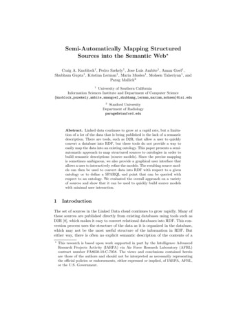
Semi-Automatically Mapping Structured Sources into the Semantic WebTop11/ε1/ε1/ε 1/εDRUG IDpharmGKBId4DRUG NAMEname31Drug111DISEASE ID1pharmGKBId3DISEASE NAMEname2: Voc, Vtc111Disease11: Vtp1: EdpACCESSION IDpharmGKBId111NAMEGENE ID11: Eopname11Pathway117pharmGKBId211Gene1: EscGENE NAME1# : weightgeneSymbol1Xxx : column nameFig. 3. The graph defines the search space for source models and provides the information for the user interface to enable users to refine the computed source model.ontology. The algorithm for building the graph has three sequential steps: graphinitialization, computing nodes closure, and adding the links.Graph Initialization: We start with an empty graph called G. In thisstep, for each semantic type assigned to a column, a new node with a uniquelabel is added to the graph. A semantic type is either a class in the ontology or a pair consisting of the name of a datatype property and its domain.We call the corresponding nodes in the graph Vtc and Vtp respectively. Applying this step on the source shown in Figure 3 results in Vtc {} and Vtp {pharmGKBId1 , pharmGKBId2 , pharmGKBId3 , pharmGKBId4 , name1 ,name2 , name3 , geneSymbol1 }.Computing Nodes Closure: In addition to the nodes that are mappedfrom semantic types, we have to find nodes in the ontology that relate thosesemantic types. We search the ontology graph and for every class node that hasa path to the nodes corresponding to semantic types, we create a node in thegraph. In other words, we get all the class nodes in the ontology from which thesemantic types are reachable. To compute the paths, we consider both propertiesand isa relationships. The nodes added in this step are called Voc . In the example,we would have Voc {T hing1 , T op1 , Gene1 , P athway1 , Drug1 , Disease1 }. InFigure 3, solid ovals represent {Vtc Voc }, which are the nodes mapped fromclasses of ontology, and the dashed ovals represent Vtp , which are the semantictypes corresponding to datatype properties.Adding the Links: The final step in constructing the graph is adding thelinks to express the relationships among the nodes. We connect two nodes in thegraph if there is a datatype property, object property, or isa relationship thatconnects their corresponding nodes in the ontology. More precisely, for each pairof nodes in the graph, u and v:– If v Vtp , i.e., v is a semantic type mapped from a datatype property, andu corresponds to the domain class of that semantic type, we create a directedweighted link (u, v) with a weight equal to one (w 1). For example, therewould be a link from P athway1 to pharmGKBId1 , because pharmGKBId1corresponds to the semantic type Pathway.pharmGKBId.
8Knoblock et al.– If u, v {Vtc Voc }, which means both of them are mapped from ontologyclasses, we put a weighted link (u, v) with w 1 in the graph only if there isan object property such as p in the ontology whose domain includes the classof u and whose range includes class of v. These links are called Eop . Note thatthe properties inherited from parents are also considered in this part, but toprioritize direct properties in the algorithm, we consider a slightly higher weightto the inherited properties. In other words, if p is defined such that its domaincontains one of the superclasses of u (at any level) and its range contains one ofthe superclasses of v, we add the link (u, v) with w 1 .– If u, v {Vtc Voc } and v is a direct or indirect subclass of u, a link (u, v)with w 1/ is added to the graph, in which is a very small value. We callthese links Esc . Subclass links have a large weight so that relationships mappedfrom properties are preferred over the relationships through the class hierarchy.The final graph is a directed weighted graph G (V, E) in which V {Vtp Vtc Voc } and E {Edp Eop Esc }. Figure 3 shows the final graph.3.3Generating Source ModelsSource models must explicitly represent the relationships between the columnsof a source. For example, after mapping columns to the Gene and Drug classes,we want to explicitly represent the relationship between these two classes. Thegraph we constructed in the previous section explicitly represents all possiblerelationships among the semantic types. We construct a source model as theminimal tree that connects the semantic types The minimal tree correspondsto the most succinct model that relates all the columns in a source, and this isa good starting point for refining the model. To compute the minimal tree, weuse one of the variations of the known Steiner Tree algorithm. Given an edgeweighted graph and a subset of the vertices, called Steiner nodes, the goal is tofind the minimum-weight tree in the graph that spans all Steiner nodes. In ourgraph, the Steiner nodes are the semantic type nodes, i.e., the set {Vtc Vtp }.The Steiner tree problem is NP-complete, but we use a heuristic algorithm [17]with an approximation ratio bounded by 2(1 1/l), where l is the numberof leaves in the optimal Steiner tree. The time complexity of the algorithm isO( Vtc Vtp V 2 ). Figure 4(a) shows the resulting Steiner tree.It is possible that multiple minimal trees exist, or that the correct interpretation of the data is specified by a non-minimal tree. In these cases, Karma allowsthe user to interactively impose constraints on the algorithms that lead to thecorrect model. We enforce these constraints on G by transforming it into a newgraph G0 , and using G0 as the input to the Steiner tree algorithm. User actionscan have three types of effects on the algorithm:Changing the semantic types: If the user changes the semantic type ofone or more columns, we re-construct the graph G and repeat all the stepsmentioned before to get the final Steiner tree.Specifying a relationship: In the Steiner tree shown in Figure 4(a), Diseaseis related to Gene through the isCausedBy property. However, in the correctmodel of the data, Gene is related to Pathway through the involves property.
Semi-Automatically Mapping Structured Sources into the Semantic Web: Steiner nodespharmGKBId4name3Top1: nodes in Steiner tree1/ε111Drug1 111name211pharmGKBId3: edges in Steiner treepharmGKBId1Disease1Pathway1 11incorrect edge1Top1name1pharmGKBId21geneSymbol1(a) Karma incorrectly infers that Gene1 causesDisease1 .pharmGKBId11111Pathway1 ε1Gene1: deleted bol1(b) User specifies that P athway1involves Gene1 .Fig. 4. Interactive refinement of the automatically computed Steiner trees.Karma allows the user to correct the model and change the relationship fromisCausedBy to involves. To force the Steiner tree algorithm to select the newlink, we first add the source (P athway1 ) and target (Gene1 ) of the link to theSteiner nodes. Then we remove all the incoming links to the target except thelink selected by the user. This means that involves would be the only link in thegraph going to Gene1 . Finally, we reduce the weight of the user link to . Thesesteps guarantee that the user link will be chosen by the Steiner algorithm. Notethat forcing a link by the user does not change graph G and it only affects G0and the Steiner nodes. Figure 4(b) illustrates the new G0 and Steiner tree afterselecting the involves relationship by the user.Generating multiple instances of a class: Consider the case that in thesource table, in addition to information about the genes involved in pathway,we also have the data about genes that cause specific diseases. This means that,for example, we have two columns Gene Name1 and Gene Name2 referring todifferent genes. Suppose that the CRF model has assigned the Gene.geneSymbolsemantic type to both columns and their corresponding nodes in the graph aregeneSymbol1 and geneSymbol2 . After constructing the graph, we would havetwo outgoing links from Gene1 to geneSymbol1 and geneSymbol2 , indicatingthat Gene Name1 and Gene Name2 are different symbols of the same Gene.However, the correct model is the one in which Gene Name1 and Gene Name2are symbols for two different genes. That is, there should be two instances ofthe Gene class, Gene1 and Gene2 that are separately connected to geneSymbol1and geneSymbol2 . To solve this problem, Karma gives the option to the user togenerate multiple instances of a class in the GUI. The user selects the Gene1node and splits it based on the geneSymbol property. Then G0 and the Steinertree are re-computed to produce the correct model.3.4User Interface for Refining Semantic ModelsKarma visualizes a source model as a tree of nodes displayed above the columnheadings of a source. Figure 5 shows the visualization of the source model corresponding to the Steiner tree shown in Figure 4(a). The root of the Steiner tree
10Knoblock et al.1467859101112“click”23classes redrelationshipFig. 5. Karma screen showing the PharmGKBPathways source. Clicking on the pencilicon brings up a menu where users can specify alternative relationships between classes.Clicking on a semantic type brings up a menu where the user can select the semantictypes from the ontology. A movie showing the user interface in action is available odeling.mp4.appears at the top, and shows the name of the class of objects that the tableis about (in our example the table is about diseases4 ). The Steiner nodes corresponding to the semantic types are shown just below the column headings. Thenodes between the root and the semantic types show the relationships betweenthe different objects represented in the table. Internal nodes of the Steiner tree(e.g., nodes 4, 5 and 8) consist of the name of an object property, shown in italicsand a class name (a subclass of the range of the property). The property definesthe relationship between the class named in the parent node and the class ofthe current node. For example, node 4 is “disrupts Pathway”, which means thatthe Disease (node 1) disrupts the Pathway represented by the columns undernode 4. The leaves of the tree (nodes 6, 7, 9, etc.) show the name of data properties. For example, node 6 is pharmGKBId, meaning that the column containsthe pharmGKBId of the Pathway in node 4.According to the model shown in Figure 5, the table contains informationabout diseases (1): the last column contains the disease names (3) and the nextto last column contains their identifiers (2). The Disease disrupts a Pathway (4),and isCausedBy a Gene (5). The Pathway is identified using its pharmGKBId in4Selection of the root is not unique for ontologies that declare property inverses.In this example, any of the classes could have been selected as the root yieldingequivalent models.
Semi-Automatically Mapping Structured Sources into the Semantic Web41115Fig. 6. Karma screen showing the user interaction to change the model of a columnfrom a Pathway label to a Drug label.the first column (6), and its name appears in the second column (7). The PathwayisTargeted by the Drug (8) whose identifier (9) and label (10) appear in the thirdand fourth columns. The gene that causes the disease (5) is identified using itspharmGKBId (11) and its geneSymbol (12).This is a plausible model, but it is incorrect because the table lists the genesinvolved in the pathways that are disrupted by the disease instead of the genesthat cause the disease; in other words, the isCausedBy property in cell 5 is incorrect. Users can edit the model to adjust the relationships between columns byclicking on the pencil icons. The pop-up in Figure 5 appears the user clicks on thepencil icon on the Gene cell (5): it shows the possible relationships correspondingto all incoming edges to the Gene 1 node in the graph shown in Figure 3. Figure 6shows the adjusted model after the user selects the “Pathway Involves” optionin Figure 5 to specify the correct relationship between the disease and the gene.The Gene cell (5) is now below Pathway (4) related using the involves property.Karma also provides capabilities to clean, normalize and transform data before modeling it. For example, a source in our scenario contained alternativesymbols for genes as comma-separated values stored in individual cells (e.g.,“CP12, P3-450, P450(PA)”). Karma provides a “split cell” command to breakthe value into multiple cells so that each value can be modeled as a separate alternative symbol. These commands can be saved in scripts to enable automaticpreprocessing of sources when source models are used to generate RDF.3.5Generation of Formal Source Model SpecificationAfter users have (optionally) imposed constraints to reflect the correct semantics, the system processes the resulting Steiner tree to generate GLAV rules thatprovide a formal specification of (1) how the sources are combined and which attributes of the source are relevant, (2) how the source data maps to the ontology,and (3) how URIs for objects in the ontology are generated. We illustrate thealgorithm that generates the GLAV rule of Figure 1 based on the Steiner treefrom Figure 4(b), which corresponds to the user interface shown in Figure 6.Class nodes generate unary predicates corresponding to classes in the ontology. The uri function builds URIs for class instances based on the key(s), orforeign key(s), in the source tables. For example, the Pathway node in Figures 3and 6 generat
The Karma process to model structured sources. 3 Modeling Structured Sources Figure 2 illustrates our approach for modeling data sources. The inputs to the process are an OWL ont