Transcription
Update on the Current Status of DG Interconnection Protection—What IEEE P-1547 Doesn’t Tell You About DG Interconnection ProtectionCharles J. MozinaContract Consultant, Protection and Protections SystemsBeckwith Electric Co., Inc.marketing@beckwithelectric.comI. INTRODUCTIONIn many parts of the United States, a significant amount of new generation capacity is being installed through theinstallation of Distributed Generation (DG) facilities. The recent 2003 Northeast Blackout will undoubtedly accelerateDG installation in the U.S. as more businesses awaken to the need for reliable on-site generation. Interconnect protectionallows DG to operate in parallel with the utility power system and is the single most important technical issue in mostDG projects. Typically, protection requirements to connect distributed generators to the utility grid had been establishedby each utility. These guidelines generally cover smaller distributed generators (10 MW or less), which are usuallyconnected to the utility system at the subtransmission and distribution level. These utility circuits are designed tosupply radial loads. Thus, the introduction of generation provides a source for redistribution of the fault current on thefeeder circuit, which can cause the loss of relay coordination and potential overvoltages. Within the past few years,there have been efforts by the IEEE, as well as individual states, to develop standards and guidelines for theinterconnection of DG. The stated goal of these standards/guidelines is to have a single document of standardtechnical requirements for DG interconnection rather than having to conform to local utility practices and guidelines.This paper examines how well this objective has been meet.The paper also updates the author’s previous papers (Ref. 3,9,10) on DG. It outlines the specific protection challengesto interconnect distributed generators into utility systems, as well as methods to reconnect these generators afterinterconnect protection tripping. It also highlights the importance of choosing the proper interconnection transformerwinding configuration and discusses potential overvoltage problems that can be caused by DGs. It is the author’sopinion that IEEE P-1547, the recently completed IEEE standard for the interconnection of DG with the utility system,does not adequately address these topics. Also, P-1547 does not address protection methods other than over/undervoltage and frequency.DGs need to be protected not only from short circuits, but also from abnormal operating conditions. Many of theseabnormal conditions can be imposed on the dispersed generator by the utility system. Examples of such abnormalconditions are: overexcitation, overvoltage, unbalanced currents, abnormal frequency and shaft torque stress due toutility automatic reclosing. When subjected to these conditions, damage or complete generator failure can occur withinseconds. Machine damage due to these causes is a major concern of DG owners. Utilities, on the other hand, aregenerally concerned that the installation of a dispersed generator will result in damage to their equipment or to theequipment of their customers.Most DGs are typically connected to the utility system at the distribution and subtransmission level. These utilitycircuits are designed to supply radial loads. Islanded operation of dispersed generation with utility loads external to theDG site on these circuits is not allowed for two major reasons:1.The utility needs to restore the outaged circuits and this effort is greatly complicated by having islandedgenerators with utility loads. Automatic reclosing is universally the first method attempted to restore powerto customers. Having islanded generators complicates both automatic reclosing, as well as manual switchingwhich requires synchronizing the generator/load islanded to the utility system.2.Power quality (voltage and frequency levels, as well as harmonics) generally cannot be maintained by theislanded dispersed generators within an acceptable level provided by the utility and could result in damageto the customer equipment.Properly designed interconnection protection should address the concerns of both the dispersed generator owner, as wellas the utility, at the lowest possible cost. The major functions of interconnect protection is to prevent system islanding by1
detecting asynchronous dispersed generator operation—in other words, determining when the generator is no longeroperating in parallel with the utility system. This detection and tripping must be rapid enough to allow automatic reclosingby the utility.II. AN UPDATE ON DG INTERCONNECTION STANDARDS AND GUIDELINESIn attempting to facilitate the installation of DG Generation, a number of efforts have been made to try to” standardize”interconnection protection requirements. This has proven to be extremely difficult due to variables such as:1.2.Design variations of utility distribution circuits: Some utilities use “fuse saving,” while other choose notto try to over trip line fuses. Some utilities use line reclosers and sectionalizers while others do not. Automaticreclosing practices vary from utility to utility.Various types of DG generators: The section of this paper on types of DG generators addresses theelectrical characteristics of the generators listed below.Synchronous Generators:Reciprocating enginesCombustion turbinesSmall hydroInduction Generators:Wind generatorsAsynchronous Generators:Micro turbinesFuel cellsPhotovoltaic3.Mixed views on specifications and performance requirements of interconnection equipment.4.Interconnection functional requirements vary from utility to utility for the same type and size of generator.IEEE P-1547 – An Attempt at a National Standard for DG InterconnectionIn this author’s view, IEEE P-1547 provides very limited guidance to the industry on interconnect protection requirementsother than calling for over/underfrequency and over/undervoltage interconnection protection. It also clearly definesinterconnection protection be installed at the Point of Common Coupling (PCC) between the DG and the utility system.The standard cites obvious requirements for DG interconnection operation but offers few methods, solutions oroptions to meet these requirements. Key issues such as: potential overvoltages, interconnection transformer choices,loss-of-utility-relay coordination, application of DG on secondary grid networks, damage to DG generators due tounbalanced current caused by utility single-phasing, and out-of-step protection are not addressed to any significantlevel. While the goal of P-1547 was to provide standard technical requirements for DG interconnection, it does this onsuch a basic level that the solutions to problems are not addressed to the degree required to help those struggling withthe problems cited in this paper. P-1547 is not a document that engineers in utilities or those consultants designing DGinterconnection protection can use to design their DG facilities. In recognition that much more work was needed, threeadditional IEEE Standards Committees were formed. These new Standards Committees are to address issues onlybriefly touched upon in P-1547. These new standard Committees are:IEEE P-1547.1; Draft Standard for the Conformance Test Procedures for Equipment Interconnecting DistributedResources with Electric Power System.IEEE P-1547.2; Draft Application Guide for IEEE 1547 Standard for Interconnecting Distributed ResourcesWith Electric Power Systems.IEEE P-1547.3; Draft Guide for Monitoring, Information Exchange, and Control of Distributed ResourcesInterconnected With Electric Power Systems.2
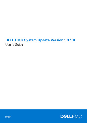
State Guidelines for DG InterconnectionA number of states have established guidelines for DG interconnection. These state guidelines are primarily filingswith the state utility commissions that outline the general requirements for interconnections of DG to utilities’ powersystems within that state. The most unique and perhaps famous state guideline is California’s Rule 21.California Rule 21- California requires a unique application of directional power relay (32) protection for antiislanding detection. Because of the high price of power in the state, most DG applications are either peakshaving or load-following where the DG generator is supplying a portion of the local load at the facility. Thus theDG is not selling power back to the utility. In SectionVII of this paper, application of directional power relayingspecified in Rule 21 is described in more detail.New York State Requirements - Provides specific functional interconnection requirements and provides statequalification procedures for interconnection devices. This eliminates the need to get approval for protectiverelays from each utility. Once interconnection protection is qualified at the state level, all utilities in New Yorkaccept it as qualified for use on their system.Texas State Requirements - Provides specific interconnection relay functional requirements similar to thosedescribed in this paper. It specifically addresses interconnection requirements for DGs connected to the utilitydistribution system through ungrounded sources.III. INTERCONNECTION VERSUS GENERATOR PROTECTIONInterconnection protection provides the protection that allows the dispersed generators to operate in parallel with theutility grid. Typically, protection requirements to connect a dispersed generator to the utility grid are established byindividual utilities or state guidelines. These guidelines generally cover smaller generators. Larger generators, generallygreater than 10 MVA, are reviewed on a case-by-case basis and are usually connected to the utility’s transmission system.These larger generators do not typically employ specific interconnection protection because they are integrated into theutility’s transmission system protection. DGs (10 MVA or smaller) are usually connected to the utility’s sub-transmissionor distribution systems. These utility circuits are designed to supply radial load. Thus, the introduction of generationprovides a source for redistributing the feeder circuit load and fault current as well as a potential source of overvoltage.Typically, interconnection protection for these generators is established at the Point of Common Coupling ( PCC) betweenthe utility and the DG. This can be at the secondary of the interconnection transformer as illustrated in Fig. 1a, or at theprimary of the transformer as illustrated in Fig.1b, depending on ownership and utility interconnect requirements.To Utility SystemTo Utility rmerCTVTCTUtility erUtility SystemIPP SystemIPP SystemGGGLocal LoadsFig. 1a Typical Interconnection Protection Applied atSecondary of the Interconnection TransformerGLocal LoadsFig. 1b Typical Interconnection Protection Applied atPrimary of the Interconnection Transformer3
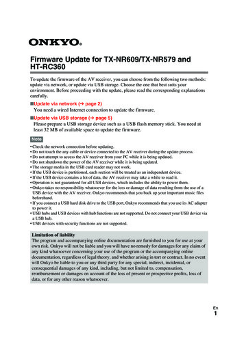
Interconnection protection satisfies the utility’s requirements to allow the DG to be connected to the grid. Its functionis three-fold:1.2.3.Disconnects the DG when it is no longer operating in parallel with the utility system.Protects the utility system from damage caused by connection of the DG, including the fault current suppliedby the DG for utility system faults and transient overvoltage.Protects the generator from damage from the utility system, especially through automatic reclosing.Generator protection is typically connected at the terminals of the generator as shown in Fig. 2.To Utility ionRelayCTGGLocal LoadsFig. 2 Typical Generator ProtectionGenerator protection provides detection of:1.2.Generator internal short circuitsAbnormal operating conditions (loss-of-field, reverse power, overexcitation and unbalanced currents)For smaller DGs, most U.S. utilities leave the responsibility to the DG owners and their consultants to select the levelof generator protection they believe is appropriate. Utilities, however, become very involved in specifying interconnectprotection. Typically, the following interconnection areas are specified by many utilities:1.2.3.4.5.6.Winding configuration of the interconnection transformerGeneral requirements of “ utility-grade” interconnection relaysCT and VT requirementsFunctional protection requirements—81O/U, 27, 59, etc.Settings of some interconnection functionsSpeed of operation required to disconnect the DG prior to utility system automatic reclosingIV. BASIC TYPES OF DG GENERATORSIEEE P-1547 discusses three basic types of DG generators. Two are traditional types of dispersed generators whichoperate interconnected with the utility system. They are induction and synchronous generators. The third type isinverter-based DGs that do not operate in synchronism with the utility system.Induction GeneratorsInduction machines are typically small—less than 500 KVA. These machines are restricted in size because theirexcitation is provided by an external source of VARS as shown in Fig. 3a. Induction generators are similar to induction4
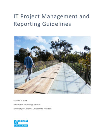
motors and are started like a motor (no synchronizing equipment needed). Induction generators are less costly thansynchronous generators because they have no field windings. Induction machines can supply real power (WATTS) tothe utility but require a source of reactive power (VARS), which in some cases is provided by the utility system. Thesegenerators can provide fault current for only a few cycles for faults on the utility system. Interconnection protectionassociated with induction generators typically requires only over/under voltage and frequency relaying. Selfcommutation is also possible with utility pole-top capacitors and can result in non-sinusoidal waveforms and overvoltage.Section VI of this paper on overvoltage discusses this condition in more detail.VAr SourceWATTSVARsGSystemVAr SourceINDUCTION- excitation provided externally- start up like a motor(e.g. no sync. equipment needed)- less costly than synchronous machinesFig. 3a Induction Generator.Synchronous GeneratorsSynchronous generators have a dc field winding to provide a source of machine excitation. They can be a source ofboth Watts and Vars to the utility system as shown in Fig. 3b and requires synchronizing equipment to be paralleledwith the utility. These generators can provide sustained fault current for faults on the utility system.WATTSG-VArsSystemField Winding dc sourceSYNCHRONOUS- dc field provides excitation- need to synchronize to utility systemFig. 3b Synchronous GeneratorsAsynchronous GeneratorsNon-traditional, small dispersed generators, especially the new micro-turbines, fuel cells and photovoltaic technologies,are being talked about more frequently as an energy source for the next decade. Most of these devices areasynchronously connected to the power system through Static Power Converters (SPCs). These SPCs are solid-statemicroprocessor controlled thyristor devices that convert DC or AC voltage at one frequency to 60 Hz system voltages.Digital electronic control of the SPC regulates the device’s power output and shuts down the machine when the utilitysystem is unavailable. Some of the newest micro-turbine controls have built in anti-islanding protection (Ref. 11) todetect when the generator is not operating in parallel with the utility. Every cycle or so, the microprocessor SPC controlattempts to increase the frequency of the micro-turbine. This is not possible if the micro-turbine is operating in parallelwith the utility system. If the generator is islanded from the utility system, the frequency will change and the control isprogrammed to trip the micro-turbine for this condition. The ability to verify the performance of this scheme throughtraditional testing is difficult. Thus the utility must rely on factory tests of the system. The need for traditionalindependent protection to avoid system islanding is thus required by some utilities while others rely on anti-islandingprotection embedded in the microprocessor control. Fig. 3c shows a typical one-line diagram for these types ofgenerators.5
GVARSWATTSSPCSystemAsynchronous TieASYNCHRONOUS- static power converter (SPC) converts generatorfrequency to system frequency- generator asynchronously connected to power systemFig. 3c Asynchronous GeneratorV. MAJOR IMPACT OF INTERCONNECTION TRANSFORMER CONNECTIONS ONINTERCONNECTION PROTECTIONAs mentioned in the previous section, the major function of interconnection protection is to disconnect the generatorwhen it is no longer operating in parallel with the utility system. DGs are generally connected to the utility system at thedistribution level. In the U.S., distribution systems range from 4 to 34.5 KV and are multi-grounded 4-wire systems. Theuse of this type of system allows single-phase, pole-top transformers, which typically make up the bulk of the feederload, to be rated at line-to-neutral voltage. Thus, on a 13.8 KV distribution system, single-phase transformers would berated at 13.8 KV/1.73 8 KV. Fig. 4 shows a typical feeder circuit. Line-to-neutral-rated transformers and lightningarrestors can be subjected to damaging overvoltages depending on the choice of DG interconnection transformer. Fivetransformer connections are widely used to interconnect dispersed generators to the utility system. Each of thesetransformer connections has advantages and disadvantages. Fig. 5 shows a number of possible choices and some ofthe advantages or problems associated with each connection.Fig. 4 Typical 4-Wire Distribution Feeder Circuit6
Fig. 5 Interconnection Transformer ConnectionsIEEE P-1547 addresses the question of overvoltages that can be caused by a DG operating in parallel with the utilitydistribution system with a single sentence that states: “The grounding scheme of the DG interconnection shall notcause overvoltages that exceed the rating of the equipment connected to the area electric power system and shall notdisrupt the coordination of the ground fault protection on the area electric system.” The consideration to do this isnot spelled out in the standard and is a major shortcoming of the document. Hopefully, grounding concerns will becovered in greater depth in the future IEEE P-1547.2 guide. The utility and DG owner have only two choices in selectingthe primary winding configuration of the interconnection transformer.1.2.Unground the primary windings (delta or wye ungrounded) and risk possible overvoltage.Ground the primary windings (wye grounded) and potentially disrupt feeder relay ground coordinationthrough the injection of unwanted ground current.Ungrounded Primary Transformer WindingsThe major concern with an interconnection transformer with an ungrounded primary winding is that after substationbreaker A (Fig. 5) is tripped for a permanent ground fault at location F1, the multi-grounded system is ungrounded. Thissubjects the L-N (line-to-neutral) rated pole-top transformer and lightning arrestors on the unfaulted phases to anovervoltage that will approach L-L voltage. This occurs if the DG is near the capacity of the load on the feeder whenbreaker A trips. The resulting overvoltages will saturate the pole-top transformer which normally operates at the kneeof the saturation curve. Many utilities use ungrounded interconnection transformers only if a 200% or more overloadon the DG occurs when breaker A trips. During ground faults, this overload level will not allow the voltage on the7
unfaulted phases to rise higher than the normal L-N voltage, avoiding pole-top transformer saturation. For this reason,ungrounded primary windings should generally be reserved for smaller DGs where overloads of at least 200% areexpected on islanding.Grounded Primary Transformer WindingsThe major disadvantage with this connection is that it provides an unwanted ground fault current for supply circuitfaults and reduces the current from breaker A at the utility substation. This can result in a loss of relay coordination.Consider the following cases:1.If the fault is near the end of the feeder, the reduction in substation ground fault current may result insubstation ground fault relaying not responding to the fault. If this is the case, the utility will have to addpole-top line reclosure to detect ground faults near the end of the feeder circuit.2.If the utility uses a “fuse saving scheme,” the reduction of source current and increase in current seen by thefuse can result in failure to over trip fuses and the resulting loss of coordination with substation relaying.Fig. 6 illustrates this point for a typical distribution circuit.3.If the fault is on an adjacent feeder (F2 in Fig. 5) the resulting ground current flow through the substation buscould result in loss of coordination and the undesirable tripping of breaker A. To avoid this situation, theovercurrent feeder relays at breaker A may have to be directionalized to respond to faults only on feeder A.Fig.6 Single-line diagram for Wye-Grounded(Pri)/Delta(Sec.) Interconnection TransformerWye-Grounded(Pri)/Delta(Sec.) Interconnection Transformer ConnectionAnalysis of the circuit in Fig. 6 also shows that even when the DG is off-line (the generator breaker is open), the groundfault current will still be provided to the utility system if the dispersed generator interconnect transformer remainsconnected. This would be the usual case since interconnect protection typically trips the generator breaker. Thetransformer at the dispersed generator site acts as a grounding transformer with zero sequence current circulating inthe delta secondary windings. In addition to these problems, the unbalanced load current on the system, which priorto the addition of the dispersed generator transformer had returned to ground through the main substation transformerneutral, now splits between the substation and the DG transformer neutrals. This can reduce the load-carrying capabilitiesof the DG transformer and create problems when the feeder current is unbalanced due to operation of single-phaseprotection devices such as fuses and line-reclosers. Even though the wye-grounded/delta transformer connection is8
universally used for large generators connected to the utility transmission system, it presents some major problemswhen used on 4-wire distribution systems. The utility should evaluate the above points when considering its use.Wye-Grounded (Pri)/Wye-Grounded (Sec) InterconnectTransformer ConnectionsThe major concern with an interconnection transformer with grounded primary and secondary windings is that it alsoprovides a source of unwanted ground current for utility feeder faults similar to that described in the previous section.It also allows sensitively set ground feeder relays at the substation to respond to ground faults on the secondary of thedispersed generator transformer (F3 in Fig. 5). This can require the utility to increase feeder ground relay pickup and/or delay tripping to provide coordination. This reduces the sensitivity and speed of operation for feeder faults and canincrease feeder circuit wire damage.IEEE P-1547 does not provide enough background to lead the reader of the standard to consider the above-cited cases.VI. OTHER SOURCES OF DG INDUCED OVERVOLTAGEThe phenomenon of self-excitation of induction generators has been known for many years. It occurs when an isolatedgenerator is connected to a system having capacitance equal to, or greater than, the magnetizing reactance requirements.Depending on the value of the capacitance, and the KW loading on the machine, voltages in the island of 1.5-2.0 perunit can be produced. To compound the problem of islanding of DGs with distribution system capacitor banks, aunique form of ferroresonance can occur that is not confined to induction generators but can also occur on synchronousmachines. Overvoltages of over 3.0 per unit can occur. The discharging and charging of the system capacitancethrough non-linear magnetizing reactance of the DG interconnection transformer produce these overvoltages. Theferroresonance associated with DG differs from the traditional ferroresonance caused by single-phase switching inthat no unbalanced condition is necessary. While the exact description of the phenomenon is contained in Ref. 4, thefollowing conditions must exist for it to occur:1.2.3.4.The DG must be separated from the utility source (islanding condition).The KW load in the island must be less than 3 times the rating of the DG.The system capacitance must be greater than 25 and less than 500 percent of the rating of the DG.There must be a transformer in the circuit to provide nonlinearity.If all these conditions exist ferroresonance can occur. What are the techniques for mitigating the resulting overvoltages?Studies have shown (Ref. 4) that both induction and synchronous generators are susceptible. Also, all types ofinterconnection transformer connections (wye-delta, delta-wye, wye-wye, delta-delta ) are susceptible. Surge arresterswill clip the peaks of the overvoltage, but will not suppress the ferroresonance condition and may be damaged in theprocess. Metal-oxide arresters have an increased ability to survive longer but can also be damaged. The most practicalsolution is to trip the DG to remove the driving source. This is not as simple as it sounds since the voltage wave shapefor this resonance condition is non-sinusoidal. An example of the voltage waveform is shown in Fig. 7 and was takenfrom field tests conducted in New York State in the 1980’s.9
50 KW synchronous DSG, 9 kw load, 100 kvar capacitance, and wye-delta stepup transformer. Maximum voltage: A 2.74 p.u., B 2.34 p.u., C 2.92 p.u.Fig.7 Overvoltage Caused by Ferroresonance (taken from Ref. 4)Frequency and voltage measurements in digital, electronic and electromechanical relays may not operate as expectedsince the waveshape is not sinusoidal. The measurement of peak overvoltage rather than RMS may provide the bestdetection solution. This method is described in Section VII of this paper.VII. DG INTERCONNECTION PROTECTION METHODS AND PRACTICESThe functional levels of interconnection protection vary widely depending on factors such as: generator size, point ofinterconnection to the utility system (distribution or subtransmission), type of generator (induction, synchronous,asynchronous) and interconnection transformer configuration (see previous section of this paper). As shown in Table1, specific objectives of an interconnection protection system can be listed, as well as the relay functional requirementsto accomplish each objective. Other than a very simplistic discussion of the detection of loss of parallel with the utility,IEEE P-1547 does not address protection areas such as: fault backfeed removal, abnormal power flow, damaging systemconditions or restoration practices addressed in this section of the paper.Interconnection Protection ObjectiveProtection Function UsedDetection of loss of parallel operation with utility system81O/U, 81R*, 27/59, 59I, TT**, 32***Fault backfeed detectionPhase Faults: 51V, 67, 21Ground Faults: 51N, 67N, 59N, 27NDetection of damaging system conditions47, 46, 78Abnormal power flow detection32Restoration25* Rate of change** Transfer Trip***Rule 21 CaliforniaTable 1 Interconnection Protection AreasDetection of Loss of Parallel Operation with the Utility SystemThe most basic and universal means of detecting loss of parallel operation with the utility is to establish an over/underfrequency (81O/U) and over/undervoltage (27/59) “window” within which the DG is allowed to operate. Whenthe DG is islanded from the utility system, either due to a fault or other abnormal condition, the frequency and voltage10
will quickly move outside the operating window if there is a significant difference between load and dispersed generationlevels. If the load and generator are near a balance at the time of separation, voltage and frequency may stay within thenormal operating window and under/overfrequency and over/undervoltage tripping may not take place. If this is a possibility,then transfer trip (TT) using a reliable means of communication may be necessary. When induction or synchronous DGsare islanded with pole-top capacitors and the generator capacity is near that of the islanded load (as described in SectionVI of this paper, a resonant condition that produces a non-sinusoidal overvoltage can occur. For these cases, aninstantaneous overvoltage relay (59I) that responds to peak overvoltage needs to be used to detect this situation.When the loss of parallel operation is detected, the dispersed generator must be separated from the utility systemquickly enough to allow the utility breaker at the substation to automatically reclose. High-speed reclosing on theutility system can occur as quickly as 15 to 20 cycles after utility substation breaker tripping. The utility needs toprovide guidance to the DG owner on the speed of separation required. The use of underfrequency relays coupled withthe need to separate the dispersed generator prior to utility breaker reclosing precludes the ability of most DGs toprovide power system support to the utility during major system disturbances. When frequency decreases due to amajor system disturbance, these generators will trip off-line. It may be possible to reduce underfrequency settings tocomply with regional Reliability Council requirements, but the required trip time cannot generally be extended to exceedautomatic reclosing times.An approach to mitigate this problem is to use rate-of-change frequency (81R) protection, which is widely used outsidethe U.S. in place of, or in conjunctions with, underfrequency (81) relaying to detect islanding of the DG. It offers theadvantage of more rapid tripping for severe DG overloads while allowing the DG to remain connected to the system whenfrequency is being slowly dragged down due to the loss of utility generation. The problem of DGs providing some systemsupport wil
IEEE P-1547 – An Attempt at a National Standard for DG Interconnection In this author ’s view, IEEE P-1547 provides very limited guidance to the industry on interconnect protection