Transcription
Chapter SevenALTERNATINGCURRENT7.1 INTRODUCTIONWe have so far considered direct current (dc) sources and circuits with dcsources. These currents do not change direction with time. But voltagesand currents that vary with time are very common. The electric mainssupply in our homes and offices is a voltage that varies like a sine functionwith time. Such a voltage is called alternating voltage (ac voltage) andthe current driven by it in a circuit is called the alternating current (accurrent)*. Today, most of the electrical devices we use require ac voltage.This is mainly because most of the electrical energy sold by powercompanies is transmitted and distributed as alternating current. The mainreason for preferring use of ac voltage over dc voltage is that ac voltagescan be easily and efficiently converted from one voltage to the other bymeans of transformers. Further, electrical energy can also be transmittedeconomically over long distances. AC circuits exhibit characteristics whichare exploited in many devices of daily use. For example, whenever wetune our radio to a favourite station, we are taking advantage of a specialproperty of ac circuits – one of many that you will study in this chapter.* The phrases ac voltage and ac current are contradictory and redundant,respectively, since they mean, literally, alternating current voltage and alternatingcurrent current. Still, the abbreviation ac to designate an electrical quantitydisplaying simple harmonic time dependance has become so universally acceptedthat we follow others in its use. Further, voltage – another phrase commonlyused means potential difference between two points.2021–22
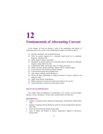
Physics7.2 AC VOLTAGE APPLIED TO A RESISTORFigure 7.1 shows a resistor connected to a source ε ofac voltage. The symbol for an ac source in a circuitdiagram is . We consider a source which producessinusoidally varying potential difference across itsterminals. Let this potential difference, also called acvoltage, be given byNICOLA TESLA (1856 – 1943)(7.1)v vm sin ω twhere vm is the amplitude of the oscillating potentialdifference and ω is its angular frequency.Nicola Tesla (1856 –1943) Serbian-Americanscientist, inventor andgenius. He conceived theidea of the rotatingmagnetic field, which is thebasis of practically allalternatingcurrentmachinery, and whichhelped usher in the age ofelectric power. He alsoinvented among otherthings the induction motor,the polyphase system of acpower, and the highfrequency induction coil(the Tesla coil) used in radioand television sets andother electronic equipment.The SI unit of magnetic fieldis named in his honour.FIGURE 7.1 AC voltage applied to a resistor.To find the value of current through the resistor, weapply Kirchhoff’s loop rule3.13), to the circuit shown in Fig. 7.1 to getvm sin ω t i Rvmsin ω tRSince R is a constant, we can write this equation asor i i i m sin ω twhere the current amplitude im is given by234(7.2)vm(7.3)REquation (7.3) is Ohm’s law, which for resistors, works equallywell for both ac and dc voltages. The voltage across a pure resistorand the current through it, given by Eqs. (7.1) and (7.2) areplotted as a function of time in Fig. 7.2. Note, in particular thatboth v and i reach zero, minimum and maximum values at thesame time. Clearly, the voltage and current are in phase witheach other.We see that, like the applied voltage, the current variessinusoidally and has corresponding positive and negative valuesduring each cycle. Thus, the sum of the instantaneous currentvalues over one complete cycle is zero, and the average currentis zero. The fact that the average current is zero, however, doesim FIGURE 7.2 In a pureresistor, the voltage andcurrent are in phase. Theminima, zero and maximaoccur at the samerespective times. ε(t ) 0 (refer to Section2021–22
Alternating Currentnot mean that the average power consumed is zero andthat there is no dissipation of electrical energy. As youknow, Joule heating is given by i 2R and depends on i 2(which is always positive whether i is positive or negative)and not on i. Thus, there is Joule heating anddissipation of electrical energy when anac current passes through a resistor.The instantaneous power dissipated in the resistor isp i 2 R i m2 R sin 2 ω tThe average value of p over a cycle is*(7.4)[7.5(b)]p i m2 R sin2 ωt 2Using the trigonometric identity, sin ω t 1/2 (1– cos 2ωt ), we have sin2 ωt (1/2) (1– cos 2ωt )and since cos2ωt 0**, we have, sin2 ω t 12Thus,1 2im R[7.5(c)]2To express ac power in the same form as dc power(P I2R), a special value of current is defined and used.It is called, root mean square (rms) or effective current(Fig. 7.3) and is denoted by Irms or I.p Geor geWestinghouse(1846 – 1914) A leadingproponent of the use ofalternating current overdirect current. Thus,he came into conflictwith Thomas Alva Edison,an advocate of directcurrent. Westinghousewas convinced that thetechnology of alternatingcurrent was the key tothe electrical future.He founded the famousCompany named after himand enlisted the servicesof Nicola Tesla andother inventors in thedevelopment of sion of hightension current, pioneeringin large scale lighting.GEORGE WESTINGHOUSE (1846 – 1914)[7.5(a)]p i 2 R i m2 R sin 2 ω t where the bar over a letter (here, p) denotes its averagevalue and . denotes taking average of the quantityinside the bracket. Since, i 2m and R are constants,FIGURE 7.3 The rms current I is related to thepeak current im by I i m / 2 0.707 im.T* The average value of a function F (t ) over a period T is given by F (t ) 1T1 sin 2ω t T1 [sin 2ω T 0] 02ω 0 2ω T** cos 2ω t T cos 2ω t dt T 02021–221F (t ) dtT 0235
PhysicsIt is defined byi1 2im m22 0.707 imI i2 (7.6)In terms of I, the average power, denoted by P is1 2im R I 2 R2Similarly, we define the rms voltage or effective voltage byP p V vm 0.707 vm2From Eq. (7.3), we havev m i mRvm (7.7)(7.8)imR22or, V IR(7.9)Equation (7.9) gives the relation between ac current and ac voltageand is similar to that in the dc case. This shows the advantage ofintroducing the concept of rms values. In terms of rms values, the equationfor power [Eq. (7.7)] and relation between current and voltage in ac circuitsare essentially the same as those for the dc case.It is customary to measure and specify rms values for ac quantities. Forexample, the household line voltage of 220 V is an rms value with a peakvoltage ofor,vm 2 V (1.414)(220 V) 311 VIn fact, the I or rms current is the equivalent dc current that wouldproduce the same average power loss as the alternating current. Equation(7.7) can also be written asP V2 / R I V (since V I R )Example 7.1 A light bulb is rated at 100W for a 220 V supply. Find(a) the resistance of the bulb; (b) the peak voltage of the source; and(c) the rms current through the bulb.Solution(a) We are given P 100 W and V 220 V. The resistance of thebulb isV 2 (220 V )R 484 ΩP100 W2236EXAMPLE 7.1(b) The peak voltage of the source isv m 2V 311 V(c) Since, P I VI P 100 W 0.454AV220 V2021–22
Alternating Current7.3 REPRESENTATION OF AC CURRENT AND VOLTAGEBY ROTATING VECTORS — PHASORSIn the previous section, we learnt that the current through a resistor isin phase with the ac voltage. But this is not so in the case of an inductor,a capacitor or a combination of these circuit elements. In order to showphase relationship between voltage and currentin an ac circuit, we use the notion of phasors.The analysis of an ac circuit is facilitated by theuse of a phasor diagram. A phasor* is a vectorwhich rotates about the origin with angularspeed ω, as shown in Fig. 7.4. The verticalcomponents of phasors V and I represent thesinusoidally varying quantities v and i. Themagnitudes of phasors V and I represent theamplitudes or the peak values vm and im of theseoscillating quantities. Figure 7.4(a) shows theFIGURE 7.4 (a) A phasor diagram for thecircuit in Fig 7.1. (b) Graph of v andvoltage and current phasors and theiri versus ωt.relationship at time t1 for the case of an ac sourceconnected to a resistor i.e., corresponding to thecircuit shown in Fig. 7.1. The projection ofvoltage and current phasors on vertical axis, i.e., vm sinω t and im sinω t,respectively represent the value of voltage and current at that instant. Asthey rotate with frequency ω, curves in Fig. 7.4(b) are generated.From Fig. 7.4(a) we see that phasors V and I for the case of a resistor arein the same direction. This is so for all times. This means that the phaseangle between the voltage and the current is zero.7.4 AC VOLTAGE APPLIEDTO ANINDUCTORFigure 7.5 shows an ac source connected to an inductor. Usually,inductors have appreciable resistance in their windings, but we shallassume that this inductor has negligible resistance.Thus, the circuit is a purely inductive ac circuit. Letthe voltage across the source be v vm sinω t. Usingthe Kirchhoff’s loop rule, ε (t ) 0 , andsince thereis no resistor in the circuit,di 0(7.10)dtwhere the second term is the self-induced Faradayemf in the inductor; and L is the self-inductance ofv LFIGURE 7.5 An ac sourceconnected to an inductor.* Though voltage and current in ac circuit are represented by phasors – rotatingvectors, they are not vectors themselves. They are scalar quantities. It so happensthat the amplitudes and phases of harmonically varying scalars combinemathematically in the same way as do the projections of rotating vectors ofcorresponding magnitudes and directions. The rotating vectors that representharmonically varying scalar quantities are introduced only to provide us with asimple way of adding these quantities using a rule that we already know.2021–22237
Physics238div v m sin ω t(7.11)dt LLEquation (7.11) implies that the equation for i(t), the current as afunction of time, must be such that its slope di/dt is a sinusoidally varyingquantity, with the same phase as the source voltage and an amplitudegiven by vm/L. To obtain the current, we integrate di/dt with respect totime:di dt dt vmL sin(ωt )dtand get,vmcos(ωt ) constantωLThe integration constant has the dimension of current and is timeindependent. Since the source has an emf which oscillates symmetricallyabout zero, the current it sustains also oscillates symmetrically aboutzero, so that no constant or time-independent component of the currentexists. Therefore, the integration constant is zero.Usingi tmlInteractive animation on Phasor diagrams of ac circuits containing, R, L, C and RLC series circuits:the inductor. The negative sign follows from Lenz’s law (Chapter 6).Combining Eqs. (7.1) and (7.10), we haveπ cos(ω t ) sin ω t , we have 2 π i i m sin ωt 2 (7.12)vmis the amplitude of the current. The quantity ω L isωLanalogous to the resistance and is called inductive reactance, denotedby XL:whereim XL ω L(7.13)The amplitude of the current is, thenim vmXL(7.14)The dimension of inductive reactance is the same as that of resistanceand its SI unit is ohm (Ω). The inductive reactance limits the current in apurely inductive circuit in the same way as the resistance limits thecurrent in a purely resistive circuit. The inductive reactance is directlyproportional to the inductance and to the frequency of the current.A comparison of Eqs. (7.1) and (7.12) for the source voltage and thecurrent in an inductor shows that the current lags the voltage by π/2 orone-quarter (1/4) cycle. Figure 7.6 (a) shows the voltage and the currentphasors in the present case at instant t1. The current phasor I is π/2behind the voltage phasor V. When rotated with frequency ω counterclockwise, they generate the voltage and current given by Eqs. (7.1) and(7.12), respectively and as shown in Fig. 7.6(b).2021–22
Alternating CurrentFIGURE 7.6 (a) A Phasor diagram for the circuit in Fig. 7.5.(b) Graph of v and i versus ωt.We see that the current reaches its maximum value later than theπ /2 Tvoltage by one-fourth of a period . You have seen that anω 4inductor has reactance that limits current similar to resistance in adc circuit. Does it also consume power like a resistance? Let us try tofind out.The instantaneous power supplied to the inductor isπ p L i v im sin ω t vm sin (ωt ) 2 i m vm cos (ωt ) sin (ωt )i m vmsin (2ωt )2So, the average power over a complete cycle is PL i m vmsin (2ω t )2i m vmsin (2ω t ) 0,2since the average of sin (2ωt) over a complete cycle is zero.Thus, the average power supplied to an inductor over one completecycle is zero.Figure 7.7 explains it in detail. Example 7.2 A pure inductor of 25.0 mH is connected to a source of220 V. Find the inductive reactance and rms current in the circuit ifthe frequency of the source is 50 Hz.Solution The inductive reactance,EXAMPLE 7.2X L 2 π ν L 2 3.14 50 25 10–3 Ω 7.85ΩThe rms current in the circuit isI V220 V 28AX L 7.85 Ω2021–22239
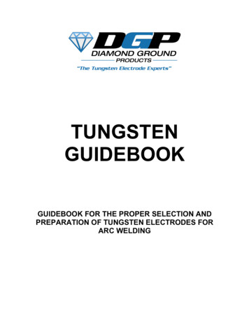
Physics0-1 Current i through the coil entering at Aincrease from zero to a maximum value. Fluxlines are set up i.e., the core gets magnetised.With the polarity shown voltage and currentare both positive. So their product p is positive.ENERGY IS ABSORBED FROM THESOURCE.1-2 Current in the coil is still positive but isdecreasing. The core gets demagnetised andthe net flux becomes zero at the end of a halfcycle. The voltage v is negative (since di/dt isnegative). The product of voltage and currentis negative, and ENERGY IS BEINGRETURNED TO SOURCE.One complete cycle of voltage/current. Note that the current lags the voltage.2-3 Current i becomes negative i.e., it entersat B and comes out of A. Since the directionof current has changed, the polarity of themagnet changes. The current and voltage areboth negative. So their product p is positive.ENERGY IS ABSORBED.2403-4 Current i decreases and reaches its zerovalue at 4 when core is demagnetised and fluxis zero. The voltage is positive but the currentis negative. The power is, therefore, negative.ENERGY ABSORBED DURING THE CYCLE2-3 IS RETURNED TO THE SOURCE.FIGURE 7.7 Magnetisation and demagnetisation of an inductor.2021–22
Alternating Current7.5AC VOLTAGE APPLIEDTO ACAPACITORFigure 7.8 shows an ac source ε generating ac voltage v vm sin ωtconnected to a capacitor only, a purely capacitive ac circuit.When a capacitor is connected to a voltage sourcein a dc circuit, current will flow for the short timerequired to charge the capacitor. As chargeaccumulates on the capacitor plates, the voltageacross them increases, opposing the current. That is,a capacitor in a dc circuit will limit or oppose thecurrent as it charges. When the capacitor is fullycharged, the current in the circuit falls to zero.When the capacitor is connected to an ac source,as in Fig. 7.8, it limits or regulates the current, butFIGURE 7.8 An ac sourcedoes not completely prevent the flow of charge. Theconnected to a capacitor.capacitor is alternately charged and discharged asthe current reverses each half cycle. Let q be thecharge on the capacitor at any time t. The instantaneous voltage v acrossthe capacitor isq(7.15)CFrom the Kirchhoff’s loop rule, the voltage across the source and thecapacitor are equal,v vm sin ω t qCTo find the current, we use the relation i i dqdtd(vm C sin ω t ) ω C vm cos(ω t )dtπUsing the relation, cos(ω t ) sin ω t , we have 2 π i im sin ω t (7.16) 2 where the amplitude of the oscillating current is im ωCvm. We can rewriteit asvm(1/ ω C )Comparing it to im vm/R for a purely resistive circuit, we find that(1/ωC) plays the role of resistance. It is called capacitive reactance andis denoted by Xc,im Xc 1/ωC(7.17)so that the amplitude of the current isim vmXC(7.18)2021–22241
PhysicsThe dimension of capacitive reactance is thesame as that of resistance and its SI unit isohm (Ω). The capacitive reactance limits theamplitude of the current in a purely capacitivecircuit in the same way as the resistance limitsthe current in a purely resistive circuit. But itis inversely proportional to the frequency andthe capacitance.A comparison of Eq. (7.16) with theFIGURE 7.9 (a) A Phasor diagram for the circuitequationof source voltage, Eq. (7.1) shows thatin Fig. 7.8. (b) Graph of v and i versus ωt.the current is π/2 ahead of voltage.Figure 7.9(a) shows the phasor diagram at an instant t1. Here the currentphasor I is π/2 ahead of the voltage phasor V as they rotatecounterclockwise. Figure 7.9(b) shows the variation of voltage and currentwith time. We see that the current reaches its maximum value earlier thanthe voltage by one-fourth of a period.The instantaneous power supplied to the capacitor ispc i v im cos(ωt)vm sin(ωt) imvm cos(ωt) sin(ωt)i m vmsin(2ωt )2So, as in the case of an inductor, the average power (7.19)i m vmi vsin(2ωt ) m m sin(2ωt ) 022since sin (2ωt) 0 over a complete cycle. Figure 7.10 explains it in detail.Thus, we see that in the case of an inductor, the current lags the voltageby π/2 and in the case of a capacitor, the current leads the voltage by π/2.EXAMPLE 7.3PC Example 7.3 A lamp is connected in series with a capacitor. Predictyour observations for dc and ac connections. What happens in eachcase if the capacitance of the capacitor is reduced?Solution When a dc source is connected to a capacitor, the capacitorgets charged and after charging no current flows in the circuit andthe lamp will not glow. There will be no change even if C is reduced.With ac source, the capacitor offers capacitative reactance (1/ω C )and the current flows in the circuit. Consequently, the lamp will shine.Reducing C will increase reactance and the lamp will shine less brightlythan before.242EXAMPLE 7.4Example 7.4 A 15.0 µF capacitor is connected to a 220 V, 50 Hz source.Find the capacitive reactance and the current (rms and peak) in thecircuit. If the frequency is doubled, what happens to the capacitivereactance and the current?Solution The capacitive reactance isXC 11 212 Ω2 π ν C 2 π (50Hz)(15.0 10 6 F)The rms current is2021–22
Alternating Current0-1 The current i flows as shown and from themaximum at 0, reaches a zero value at 1. The plateA is charged to positive polarity while negative chargeq builds up in B reaching a maximum at 1 until thecurrent becomes zero. The voltage vc q/C is in phasewith q and reaches maximum value at 1. Currentand voltage are both positive. So p vci is positive.ENERGY IS ABSORBED FROM THE SOURCEDURING THIS QUAR TER CYCLE AS THECAPACITOR IS CHARGED.1-2 The current i reverses its direction. Theaccumulated charge is depleted i.e., the capacitor isdischarged during this quarter cycle.The voltage getsreduced but is still positive. The current is negative.Their product, the power is negative.THE ENERGY ABSORBED DURING THE 1/4CYCLE 0-1 IS RETURNED DURING THIS QUARTER.One complete cycle of voltage/current. Note that the current leads the voltage.2-3 As i continues to flow from A to B, the capacitoris charged to reversed polarity i.e., the plate Bacquires positive and A acquires negative charge.Both the current and the voltage are negative. Theirproduct p is positive. The capacitor ABSORBSENERGY during this 1/4 cycle.3-4 The current i reverses its direction at 3 and flowsfrom B to A. The accumulated charge is depletedand the magnitude of the voltage vc is reduced. vcbecomes zero at 4 when the capacitor is fullydischarged. The power is negative.ENERGYABSORBED DURING 2-3 IS RETURNED TO THESOURCE. NET ENERGY ABSORBED IS ZERO.FIGURE 7.10 Charging and discharging of a capacitor.2021–22243
PhysicsI V220 V 1.04 AX C 212 ΩEXAMPLE 7.4The peak current isi m 2I (1.41)(1.04 A ) 1.47 AThis current oscillates between 1.47A and –1.47 A, and is ahead ofthe voltage by π/2.If the frequency is doubled, the capacitive reactance is halved andconsequently, the current is doubled.Example 7.5 A light bulb and an open coil inductor are connected toan ac source through a key as shown in Fig. 7.11.FIGURE 7.11EXAMPLE 7.5The switch is closed and after sometime, an iron rod is inserted intothe interior of the inductor. The glow of the light bulb (a) increases; (b)decreases; (c) is unchanged, as the iron rod is inserted. Give youranswer with reasons.Solution As the iron rod is inserted, the magnetic field inside the coilmagnetizes the iron increasing the magnetic field inside it. Hence,the inductance of the coil increases. Consequently, the inductivereactance of the coil increases. As a result, a larger fraction of theapplied ac voltage appears across the inductor, leaving less voltageacross the bulb. Therefore, the glow of the light bulb decreases.7.6 AC VOLTAGE APPLIED TO A SERIES LCR CIRCUITFigure 7.12 shows a series LCR circuit connected to an ac source ε. Asusual, we take the voltage of the source to be v vm sin ωt.If q is the charge on the capacitor and i thecurrent, at time t, we have, from Kirchhoff’s looprule:diq iR v(7.20)dtCWe want to determine the instantaneouscurrent i and its phase relationship to the appliedalternating voltage v. We shall solve this problemby two methods. First, we use the technique ofphasors and in the second method, we solveEq. (7.20) analytically to obtain the time–dependence of i .LFIGURE 7.12 A series LCR circuitconnected to an ac source.2442021–22
Alternating Current7.6.1 Phasor-diagram solutionFrom the circuit shown in Fig. 7.12, we see that the resistor, inductorand capacitor are in series. Therefore, the ac current in each element isthe same at any time, having the same amplitude and phase. Let it bei im sin(ωt φ )(7.21)where φ is the phase difference between the voltage across the source andthe current in the circuit. On the basis of what we have learnt in the previoussections, we shall construct a phasor diagram for the present case.Let I be the phasor representing the current in the circuit as given byEq. (7.21). Further, let VL, VR, VC, and V represent the voltage across theinductor, resistor, capacitor and the source, respectively. From previoussection, we know that VR is parallel to I, VC is π/2behind I and VL is π/2 ahead of I. VL, VR, VC and Iare shown in Fig. 7.13(a) with apppropriate phaserelations.The length of these phasors or the amplitudeof VR, VC and VL are:vRm im R, vCm im XC , vLm im X L(7.22)The voltage Equation (7.20) for the circuit canbe written asvL vR vC v(7.23)The phasor relation whose vertical componentgives the above equation isVL VR VC V(7.24)FIGURE 7.13 (a) Relation between thephasors VL, VR, VC, and I, (b) Relationbetween the phasors VL, VR, and (VL VC)for the circuit in Fig. 7.12.This relation is represented in Fig. 7.13(b). SinceVC and VL are always along the same line and inopposite directions, they can be combined into a single phasor (VC VL)which has a magnitude vCm – vLm . Since V is represented as thehypotenuse of a right-triangle whose sides are VR and (VC VL), thepythagorean theorem gives:2vm2 vRm (vCm v Lm )2Substituting the values of vRm, vCm, and vLm from Eq. (7.22) into the aboveequation, we havevm2 (im R )2 (i m X C i m X L )2 im2 R 2 ( X C X L )2 or, i m vm[7.25(a)]R ( X C X L )22By analogy to the resistance in a circuit, we introduce the impedance Zin an ac circuit:im vmZwhere Z [7.25(b)]R 2 ( X C X L )2(7.26)2021–22245
PhysicsSince phasor I is always parallel to phasor VR, the phase angle φis the angle between VR and V and can be determined fromFig. 7.14:tan φ vCm v Lmv RmUsing Eq. (7.22), we haveXC X L(7.27)REquations (7.26) and (7.27) are graphically shown in Fig. (7.14).FIGURE 7.14 ImpedanceThis is called Impedance diagram which is a right-triangle withdiagram.Z as its hypotenuse.Equation 7.25(a) gives the amplitude of the current and Eq. (7.27)gives the phase angle. With these, Eq. (7.21) is completely specified.If XC XL, φ is positive and the circuit is predominantly capacitive.Consequently, the current in the circuit leads the source voltage. IfX C X L, φ is negative and the circuit is predominantly inductive.Consequently, the current in the circuit lags the source voltage.Figure 7.15 shows the phasor diagram and variation of v and i with ω tfor the case XC XL.Thus, we have obtained the amplitudeand phase of current for an LCR series circuitusing the technique of phasors. But thismethod of analysing ac circuits suffers fromcertain disadvantages. First, the phasordiagram say nothing about the initialcondition. One can take any arbitrary valueof t (say, t1, as done throughout this chapter)and draw different phasors which show therelative angle between different phasors.The solution so obtained is called thesteady-state solution. This is not a generalFIGURE 7.15 (a) Phasor diagram of V and I.solution. Additionally, we do have a(b) Graphs of v and i versus ω t for a series LCRtransient solution which exists even forcircuit where XC XL.v 0. The general solution is the sum of thetransient solution and the steady-statesolution. After a sufficiently long time, the effects of the transient solutiondie out and the behaviour of the circuit is described by the steady-statesolution.tan φ 7.6.2 Analytical solutionThe voltage equation for the circuit isLdiq Ri vCdt vm sin ωt246We know that i dq/dt. Therefore, di/dt d2q/dt2. Thus, in terms of q,the voltage equation becomes2021–22
Alternating Currentd 2qdq q R vm sin ω t(7.28)2dt CdtThis is like the equation for a forced, damped oscillator, [see Eq. {14.37(b)}in Class XI Physics Textbook]. Let us assume a solutionLq qm sin (ω t θ )so that[7.29(a)]dq qm ω cos(ω t θ )dt[7.29(b)]d2q qm ω 2 sin(ω t θ )dt 2Substituting these values in Eq. (7.28), we getandqm ω [ R cos(ω t θ ) ( X C X L )sin(ω t θ )] vm sin ωt[7.29(c)](7.30)where we have used the relation Xc 1/ωC, XL ω L. Multiplying anddividing Eq. (7.30) by Z R 2 ( X c X L ) , we have2(X X L ) R qm ω Z cos(ω t θ ) Csin(ω t θ ) v sin ω tmZ Z Now, letandR cos φZ(XC X L ) sin φZXC X LRSubstituting this in Eq. (7.31) and simplifying, we get:so that(7.31)φ tan 1qm ω Z cos(ω t θ φ ) vm sin ω tComparing the two sides of this equation, we see that(7.32)(7.33)vm qm ω Z i m Zwherei m qm ω[7.33(a)]ππor θ φ22Therefore, the current in the circuit isand θ φ i [7.33(b)]dq qm ω cos(ω t θ )dt im cos(ωt θ )or i imsin(ωt φ )where i m vm Z 1and φ tan(7.34)vm[7.34(a)]R ( X C X L )2XC XLR22472021–22
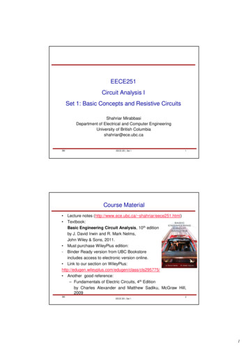
PhysicsThus, the analytical solution for the amplitude and phase of the currentin the circuit agrees with that obtained by the technique of phasors.7.6.3 ResonanceAn interesting characteristic of the series RLC circuit is the phenomenonof resonance. The phenomenon of resonance is common among systemsthat have a tendency to oscillate at a particular frequency. This frequencyis called the system’s natural frequency. If such a system is driven by anenergy source at a frequency that is near the natural frequency, theamplitude of oscillation is found to be large. A familiar example of thisphenomenon is a child on a swing. The swing has a natural frequencyfor swinging back and forth like a pendulum. If the child pulls on therope at regular intervals and the frequency of the pulls is almost thesame as the frequency of swinging, the amplitude of the swinging will belarge (Chapter 14, Class XI).For an RLC circuit driven with voltage of amplitude vm and frequencyω, we found that the current amplitude is given byim vm ZvmR 2 ( X C X L )2with Xc 1/ωC and XL ω L . So if ω is varied, then at a particular frequency()22ω0, Xc XL, and the impedance is minimum Z R 0 R . Thisfrequency is called the resonant frequency:X c X L oror ω 0 1ω0 C ω0 L1LC(7.35)At resonant frequency, the current amplitude is maximum; im vm/R.Figure 7.16 shows the variation of im with ω ina RLC series circuit with L 1.00 mH, C 1.00 nF for two values of R: (i) R 100 Ωand (ii) R 200 Ω. For the source applied vm 100 V. ω0 for this case is1LC 1.00 106rad/s.We see that the current amplitude is maximumat the resonant frequency. Since im vm / R atresonance, the current amplitude for case (i) istwice to that for case (ii).Resonant circuits have a variety ofFIGURE 7.16 Variation of im with ω for twoapplications,for example, in the tuningcases: (i) R 100 Ω, (ii) R 200 Ω,mechanism of a radio or a TV set. The antenna ofL 1.00 mH.a radio accepts signals from many broadcastingstations. The signals picked up in the antenna acts as a source in the248tuning circuit of the radio, so the circuit can be driven at many frequencies.2021–22
Alternating CurrentBut to hear one particular radio station, we tune the radio. In tuning, wevary the capacitance of a capacitor in the tuning circuit such that theresonant frequency of the circuit becomes nearly equal to the frequencyof the radio signal received. When this happens, the amplitude of thecurrent with the frequency of the signal of the particular radio station inthe circuit is maximum.It is important to note that resonance phenomenon is exhibited by acircuit only if both L and C are present in the circuit. Only then do thevoltages across L and C cancel each other (both being out of phase)and the current amplitude is vm/R, the total source voltage appearingacross R. This means that we cannot have resonance in a RL orRC circuit.Sharpness of resonanceThe amplitude of the current in the series LCR circuit is given byvmim 1 R2 ω L ω C 2and is maximum when ω ω 0 1/ L C . The maximum value isi mmax vm / R .For values of ω other than ω0, the amplitude of the current is lessthan the maximum value. Suppose we choose a value of ω for which thecurrent amplitude is 1/ 2 times its maximum value. At this value, thepower dissipated by the circuit becomes half. From the curve inFig. (7.16), we see that there are two such values of ω, say, ω1
Physics 234 NICOLA TESLA (18 5 6 – 1943) Nicola Tesla (1856 – 1943) Serbian-American scientist, inventor and genius. He conceived the idea of the rotating magnetic field, which is the basis of practically all alternating current machinery, and which helped usher in the age of electric pow