Transcription
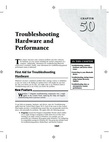
CHAPTER 7. MAINTENANCE & TROUBLESHOOTINGChapter 7.MAINTENANCE & TROUBLESHOOTINGChapter ObjectivesMai ntenanceThe infonnatlon In this chapter wUl enable you to: Maintain the system's components to ensure smooth.efficient operation Isolate and resolve system hardware and softwareproblems Use this chapter as a quick reference tool for a descriptionof system error codesThe following system components require periodicmaintenance: Spare PartsTable189The MotorThe DriveTable 7-1 provides a list of recommended spare parts to usewith the AX. system.Part DescrlDtionChoice of two drives:AXHAXLMechanical Screws (6-32 x 1/4)Universal Mountina Bracket5-Position Terminal Connector Phoenix6-Position Terminal Connector, Phoenix8-Position Terminal Connector, Phoenix11-Position Terminal Connector, PhoenixFan Kit (standard on AXH Drives)Part NumberAXH-DRIVEAXL-DRIVE51-006037-0153-006007 1AFKTable 7-1. Recommended Spare Parts for the AX System
190AX DRIVE USER GUIDEMotorMaintenanceYou should inspect all mechanical parts of the motorregularly to ensure that no bolts or couplings have becomeloose dUring normal operation. This will prevent minorproblems from developing into more serious problems.The ball bearings used in the Compumotor-supplied motorsare not sealed against severe environments. but arepermanently lubricated and do not require any maintenance.You should inspect the motor cables periodically for signs ofwear. This inspection inteIVal is duty-cycle. environment.and travel-length dependent. You should not apply excessivetensile force to the cable. Do not bend the cable beyond a oneinch radius of CUIVature during normal operation. Tightenall cable solationCheck that the drive heatsink is free of particles and has afree flow of air over its entire surface. Enclosures must beconnected to earth ground through a grounding electrodeconductor to provide a low-impedance path for ground-faultor noise-induced currents. All earth ground connections mustbe continuous and permanent.This section discusses methods to identify. isOlate. andresolve problems that may occur with your AX Drive.When your system does not function properly (or as you expectit to operate), the first thing that you must do is identify andisolate the problem. When you accomplish this. you caneffectively begin to eradicate and resolve the problem.Try to determine if the problem is mechanical. electrical. orsoftware-related. Can you repeat or re-create the problem?Do not attempt to make quick rationalizations aboutproblems. Random events may appear to be related. but theyare not necessarily contributing factors to your problem. Youmust carefully investigate and decipher the events that occurbefore the subsequent system problem.You may be experiencing more than one problem. You mustsolve one problem at a time. Log (document) all testing andproblem isolation procedures. You may need to review andconsult these notes later. This will also prevent you fromduplicating your testing efforts.Isolate each system component and ensure that eachcomponent functions properly when it is run independently.You may have to remove your system components and reinstall them component-by-component to detect the problem.If you have additional components available. you may wantto use them to replace existing components in your system tohelp identify the source of the problem.
CHAPTER 7. MAINTENANCE & TROUBLESHOOTING191Once you have isolated the problem. take the necessary stepsto resolve it. Refer to the problem solutions contained in thischapter. If your system's problem persist. contact ParkerCompumotor's Applications Department at (800) 358-9070.Motor Fallsto MoveTest the motor to see if it has holding torque. If there is noholding torque. here are some probable causes: There is no AC power. Current selection DIP switches are not set properly (see themotor current selection table in Chapter 6. HardwareReference). There are bad connections or bad cables. Disconnect thepower connector. then use an ohm meter to monitorcontinuity between the motor-to-drive cable. The drive may be disabled through software (STIcommand).If the unit has holding torque and the motor shaft still fails tomove. here are some probable causes: The limit switches have been tripped or are faulty. Makesure that your limit switches are OFF or that the limits aredisabled (LD3 command). The load is jammed. You should hear the drive attemptingto move the motor. Remove AC power from the drive andverify that you can move the load manually away from thepoint of the jam. Indexer parameters are Incorrectly set up. If certainparameters are out of range or are missing. the motor willnot move when you issue the Go (G) command.Use R. RA. RB. and RS status commands to detennine what ispreventing the move. Also check A. V. and D commands tomake sure that all the parameters are set properly. Thefollowing are additional troubleshooting techniques: Check the motor for damage. Also check the motor cableto see if it is damaged or shortened. These conditions maycause the drive to fault. Ohm the motor and cables to make sure that short-circuitsdo not exist between phases or to earth GND. On your mostsensitive scale. the resistance across each motor phaseshould be conSistently low (but not zero) and similar toeach other. On your highest scale. the resistance betweenmotor phases and between each phase and earth groundshould be infinite.
192AX DRIVE USER GUIDEFault LEDMotor StallsThere is a red FAULT LED located on the connector-side of theAX dIive. The LED may be activated (illuminated) if one of thefollowing conditions exists: Shutdown: You commanded the drtve to shutdown. Usethe Sn!) command to tum the drtve on again. Over-temperature: The drive may be overheating(heatsink temperature is above 149 F (65 C). You mayconSider cooling the drive and/or enclosure. Installing afan kit on the drive would help the problem. Short-circuit: A short-circuit exists in the motor currentoutput. Use an ohm meter to make sure that there is not ashort-circuit between phase A. phase B. or to earth ground.NOTE: Make sure power has been removed fHd'ore you testthe motor. Brown-out: Check the AC input voltage to make sure thatthe drive is receiving more than 95VAC.A motor stall during acceleration may be caused by one ormore of the following factors: The torque requirements may be excessiveThe acceleration ramp may be too steepThe load inertia and motor inertia may be grosslymismatched.Lower acceleration may be required.If the motor stalls during the constant velocity portion of amove. the shaft and/or coupler may be damaged or bindingdue to improper coupling or excessive motor load.A stall may occur if the DIP switch setting for the motorcurrent selection is incorrect. The motor may not be receivingenough current to operate.A stall may also be detected in closed loop mode if the encoderresolution (ER) is not set properly. or if the encoder inputchannels (A and B) are reversed.Motor Fallsto Run atHighSpeedsThe motor may fail to run at high speeds due to the followingfactors: It is possible that the motor may not produce enoughtorque to move a given load at these velOCities. Check thetorque/speed curve in Chapter 6 and make sure you aretrying to run the motor in the proper range. The indexer can produce pulses faster than the drtve canmake the motor move. The motor may not have the proper load-to-rotor inertia.The maximum ratio is 10: 1.
CHAPTER 7. MAINTENANCE & TROUBLESHOOTINGMotor IsJerky orWeakMotorOverheats193Check that there are no mechanical problems at the loadcausing highly variable loading condition. Disconnect themotor from the load and run it without a load connected. Keepin mind that the motor will run best with a load of equalinertia; with no load. it will not attain full speed. Tty tomanually tum the motor shaft; this will detenntne if themotor is maintaining full holding torque. Check the DIPswitches for proper current settings.If the motor exceeds its maximum motor case temperaturerating. failure will eventually result. Check your DIP Switchsettings to ensure that the current setting is correct for themotor you are using (refer to Chapter 6. Hardware Reference).The Standby Current feature (set with the SC or the SCAcommand) allows you to reduce the motor current from 13%to 100% when the motor is not moving. If the motor is hotafter a long period at standstill. check the standby currentwith a current probe.Motor ShaftWearsThe motor shaft may wear prematurely if there is foreignmaterial rubbing against the shaft. or if the load is notcoupled properly.1/0 SwitchIf you are having problems using the Trigger (TR). Home (GH)failurecommands. and the Trigger. Home. CWo CCW and SequenceSelect inputs. you must first check your wiring for properinstallation. Use an Ohm meter to verify proper connectionof the switches and inputs. If the hardware connection seemscorrect. you can manually change the input Switches and usethe IS command to verify if the AX recognizes the inputchange. The IS command provides a hardware status of theAX inputs. If the status does not change. check the hardwaresettings and wiring.RemoteSequencing(BCDInputs)failureIf you are having problems trying to run sequences from BCDinterfaces. the first thing you must verify is the hardwareinterface. Use the Ohm meter to verify proper wiring. Thenuse the IS conunand to read the status of the inputs. Changethe input setting and check the Input Status (IS) again to makesure that the AX recognized the change in the sequence selectinput. Make sure that your BCD input is calling the propersequences. Check Chapter 6. Hardware Reference. for theSequence Select Table. If you have a problem running asequence from the remote input, try running the sequenceusing the XR command before attempting to run it using BCDinput. Make sure you cycle power or issue a Z command afteryou enter an XP8 or XP9 command.
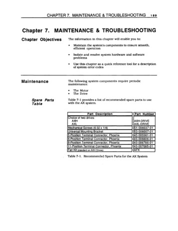
194AX DRIVE USER GUIDEReducingElectrical NoiseElectricalNoiseThis section discusses the sources and methods of suppressingelectrical noise.When an AX Drive system is operated in an environment inwhich there is an excessive amount of electrical noise. specialcare must be taken to eliminate sources of possible noiseinterference. Potential sources of electrical noise includeinductive devices such as solenOids. relays. motors. andmotor starters when they are operated by a hard contact.Compumotor recommends that you mount the AX Drive in aNEMA enclosure to protect the drive from electrical noise.For further information on avoiding electrical noise. refer tothe technical data section of the Compumotor Motion ControlCatalog.Noise suppression devices may be necessary when sources ofelectrical noise are connected to the same AC power source orare in close proximity to electronic eqUipment. You may alsoneed to install noise suppression devices if you have multipledrives attached to the same AC power source. Figure 7-1shows some recommended suppression devices for most smallloads. For best results. install these devices as close aspossible to the inductive load.ACr-DIODEVARISTOR (MeV)t "--11. Can be saved forboth AC and DCcircuits2. Use 500-1000ohm for Rand0.1 - 0.2 microF@200VandDCFor DC circuit onlyCan be used forboth AC and DCcircuitsFigure 7-1. Noise Suppression DevicesYou should Install the AX Drive in an enclosure to protect itEnclosureConsiderations against atmospheriC contaminants such as oll. moisture, anddirt. The National Electrical Manufacturers Association(NEMA) has established standards that define the degree ofprotection that electrical enclosures provide. The enclosureshould conform to NEMA Type 12 standards if the intendedenvironment is industrial and contains airbornecontaminants. Proper layout of components is required toensure suffiCient cooling of eqUipment within the enclosure.
CHAPTER 7. MAINTENANCE & TROUBLESHOOTINGSources ofElectricalNoise195NOise-related difficulties can range in severity from minorpositioning errors to damaged equipment from run-awaymotors crashing through limit switches. In microprocessorcontrolled equipment. the processor constantly retrievesinstructions from memory in a controlled sequence. If anelectrical disturbance occurs, it may cause the processor tomisinterpret instructions or access the wrong data. This canbe catastrophiC to the program and force you to reset theprocessor.Since electrical noise is not visible, it is very difficult todetect. Some possible sources are as follows: Power line noiseExternally conducted nOiseTransmitted noiseGround loopsThe following electrical devices are particularly apt togenerate unwanted electrical noise conditions: Coil-driven devices (conducted and power line noise) SCR-ftred heaters (transmitted and power line noise) Motors and motor drives (transmitted and power linenoise) Welders: electric (transmitted and power line nOise)The AX Drive is capable of delivering 6 amps on a 170V rail tothe motor. This is pulse width modulated at a 20 kHz rate:consequently. the AX Drive must be considered a source ofelectrical noise.POWER LINENOISEPower line noise is usually easy to resolve due to the widevariety of line filtering eqUipment that is available to themotion control industry. Only the most severe electricalnoise problems will require you to use an isolationtransformer. You will have to use line filtering equipmentwhen other devices connected to the local power line areswitching large amounts of current (especially if theswitching occurs at a high frequency).Any device that has coils is likely to disrupt the power linewhen it is Switched off. Surge suppressors. such as metaloxide varistors (MOY's) are capable of limiting this type ofelectrical noise. A series RC network across the coil is also aneffective means of eliminating the problem (resistance: 500 to1,000 0; capacitance: 0.1 to 0.2 ). Coil-driven devices(inductive loads) include relays. solenoids. contactors.clutches. brakes. and motor starters.
196AX DRIVE USER GUIDEEXTERNALLYCONDUCTEDNOISEExternally-conducted noise is similar to power line noise. butthe disturbances are created on signal and ground wires thatare connected to the indexer. This kind of noise can get intologic circuit ground or into the processor power supply andscramble the program. The problem in this instance is thatcontrol eqUipment often shares a common DC ground wirethat may be connected to several devices (such as a DC powersupply. programmable controller. remote switches. etc.).When a source of noise like a relay or solenoid is attached tothe DC ground. it may cause disturbances within the indexer.To solve the noise problem caused by DC mechanical relaysand solenoids. you must connect a diode backwards across thecoil to clamp the induced voltage kick that the coil willproduce. The diode should be rated a four times the coilvoltage and ten times the coil current. Using solid state relaysis another way to eliminate this problem. See Figure 7-1.Multiple devices on the same circuit should be groundedtogether at a single point.Furthermore. power supplies and programmable controllersoften have DC common tied to Earth (AC power ground). As arule. it is preferable to have the indexer signal ground or DCcommon floating with respect to Earth. This prevents sourcesof electrical noise that are grounded to Earth from sendingnoise into the indexer. When you cannot float the signalground. you should make the Earth ground connection at onlyone point.In many cases. optical isolation may be required tocompletely eliminate electrical contact between the indexerand a noisy environment. Solid state relays provide this typeof isolation.TRANSMITTEDNOISETransmitted nOise is picked up by external connections to theindexer. and in severe cases can attack an indexer with noexternal connections. The indexer enclosure will typicallyshield the electronics from this. but openings in the enclosurefor connections and front panel controls may leak. As withall electrical eqUipment. the indexer chassis should bescrupulously connected to Earth to minimize this effect.When high current contacts open. they draw an arc. producinga burst of broad spectrum radio frequency noise that can bepicked up on an indexer limit switch or other wiring. Highcurrent and high-voltage wires have an electrical field aroundthem. and may induce noise on signal wiring. espeCially whenthey are tied in the same wiring bundle or conduit.
CHAPTER 7. MAINTENANCE & TROUBLESHOOTING197When this kind of problem occurs, it is time to think aboutshielding signal cables or isolating the signals. A propershield surrounds the signal wires to intercept electrical fields,but this shield must be tied to Earth to drain the inducedvoltages. At the very least, wires should be run in twistedpairs to limit straight line antenna effects.Most Compumotor cables have shields tied to Earth, but insome cases the shields must be grounded at installation time.Installing the indexer in a NEMA electrical enclosure ensuresprotection from this kind of noise, unless noise-producingequipment is also mounted inside the enclosure. Connectionsexternal to the enclosure must be shielded.Even the worst noise problems in environments near 600 ampwelders and 25kW transmitters have been solved usingenclosures, conduit, optical isolation,and single point groundtechniques.GROUNDLOOPSGround Loops are the most mysterious noise problems. Theyseem to occur most often in systems where a control computeris using RS-232C communication. Symptoms like garbledtransmissions and intermittent operation are typical.The problem occurs in systems where multiple Earth groundconnections exist, particularly when these connections arefar apart.Suppose an AX is controlling an axis, and the limit switchesuse an external power supply. The AX is controlled by acomputer in another room. If the power supply Common isconnected to Earth, the potential exists for ground loopproblems. This is because most computers have their RS232C Signal common tied to Earth. The loop starts at the AXlimit switch ground, goes to Earth through the power supply toEarth at the computer. From there, the loop returns to the AX.through RS-232C signal ground. If a voltage potential existsbetween power supply Earth and remote computer Earth,ground current will flow through the RS-232C ground creatingunpredictable results.The way to test for and ultimately eliminate a ground loop isto lift or cheat Earth ground connections in the system untilthe symptoms disappear.
198AX DRIVE USER GUIDEDefeatingNoiseThe best time to handle electrical noise problems is beforethey occur. When a motion control system is in the deSignprocess, the designer should consider the following set ofgUidelines for system wiring in order of importance:1. Put surge suppression components on all electrical coils:ReSistor / capacitor fUters, MOVs, Zener and clampingdiodes.2. Shield all remote connections, use twisted pairs. Shieldshould be tied to Earth at one end.3. Put all microelectrical components in an enclosure. Keepnoisy devices outside, watch internal temperature.4. Ground Signal common wiring at one point. Float thisground from Earth if possible.5. Tie all mechanical grounds to Earth at one point. Runchassis and motor grounds to the frame, frame to Earth.6. Isolate remote Signals. Solid state relays or opto isolatorsare recommended.7. Filter the power line. Use common RF filters, isolationtransformer for worst case.A noise problem must be identified before it can be solved.The obvious way to approach a problem situation is toeliminate potential noise sources until the symptomsdisappear, as in the case of ground loops. When this is notpractical, use the above gUidelines to shotgun the installation.ReferencesInformation about the equipment referred to in this chaptermay be obtained by calling the numbers listed below: Corcom line filters, (312) 680-7400 Opto-22 optically isolated relays, (714) 891-5861 Crydom optically isolated relays, (213) 322-4987 Potter Brumfield optically isolated relays, (812) 386-1000 General Electric MOVs, (315) 456-3266 Teal ElectrOnics Corporation-specializing in power lineproducts, (BOO) 888-TEAL.
CHAPTER 7. MAINTENANCE & g199Procedures for troubleshooting three-wire RS-232Ccommunications are as follows:1. For single-axis applications. make certain the transmit(pin 2) of the host is wired to the receive ( pin 1) of the AXunit. Also. make sure that the receive (pin 3) of the host iswired to the transmit (pin 2) of the AX unit.ny switching the receive and transmit wires oneither the host or peripheral if you faU to get anycommunication.N01E:2. If you have a daisy-chained system. make sure thefollowing connections are made: Transmit (AX. pin 2) connected to receive (AX pin 1) ofthe successive AX units In the chainCOM (AX pin 3) is connected between AX units and toGND (pin 7) on the hostTransmit (AX pin 2) of the last AX unit in the chainconnected to the receive (pin 3) on the hostTransmit (pin 2) of the host connected to the receive(AX. pin 2) on the first AX unit in the chain3. Some computer serial ports require handshaking.Typically. you can disable the handshaking function byjumpertng RrS to CTS (usually pins 4 and 5) and DSR toom (usually pins 6 and 20). Refer to your computer orterminal user gUide for exact instructions.4. Configure the host and peripheral to the same baud rate.number of data bits. number of stop bits. and parity.5. If you receive double characters (for instance. if you type Aand receive AAl. your computer is set to half-duplex.Consult your computer or terminal emulator user manualfor Instructions on how to change the set-up to full-duplex.6. Use DC common or signal ground as your reference. 00Nar use earth ground.7. Cable lengths should not exceed 50 ft. unless you are usingsome form of line driver. optical coupler. or shield. Aswith any control signal. be sure to shield the cable to earthground at one end only.8. To test your terminal or terminal emulation software forproper 3-wire communication. unhook your peripheraldevice and transmit a character. You should not receivean echoed character. If you do. you are in half-duplexmode. Jumper the host's transmit and receive lines andsend another character. You should receive the echoedcharacter. If not. consult the manufacturer of the host'sserial Interface for proper pin-outs.
200AX DRIVE USER GUIDEReturning TheSystemIf you must return your AX system to effect repairs orupgrades. use the following steps:1. Get the serial number and the model number of thedefective unit. and a purchase order number to coverrepair costs in the event the unit is determined by ParkerCompumotor to be out of warranty.2. Before you ship the drive to Parker Compumotor. havesomeone from your organization with a technicalunderstanding of the AX system and its applicationinclude answers to the following questions: What is the extent of the failure/reason for return?How long did it operate?How many units are still working?How many units failed?What was happening when the unit failed (i.e .installing the unit. cycling power. starting otherequipment. etc)?How was the product configured (in detail)?What. if any. cables were modified and how?With what equipment is the unit interlaced?What was the application?What was the system sizing (speed. acceleration. dutycycle. inertia torque. friction. etc.)?What was the system environment (temperature.enclosure. spacing. unit orientation. contaminants.etc.)?What upgrades. if any. are required (hardware.software. user guide)?3. Call Parker Compumotor for a Return MaterialAuthOrization IRMA) number. Returned products cannotbe accepted without an RMA number. The phone numberfor Parker Compumotor Applications Department is (800)358-9070.4.Ship the unit to:Parker Compumotor Corporatlon5500 BUSiness Park DriveRohnert Park. CA 94928Attn: RMA # xxxxxxx
Electrical Noise Electrical Noise Enclosure Considerations This section discusses the sources and methods of suppressing electrical noise. When an AX Drive system is operated in an environment in which there is an excessive amount of electrical noise. special care must be t