Transcription
DEC13-06High- Current Pulse Generator
Team CompositionMembersAdvisorsGreg BulleitStephen ChievMatt StegemannHo Hsu*Wen Ya Ting*Li-yeh Yang*Shih-yao Yen*Robert BoudaDr. Mani MinaJohn PritchardClientHigh-Speed SystemsEngineering Laboratory*First semester only, fromTatung University in TaiwanDEC13-06
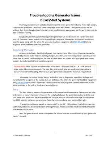
Transcranial Magnetic Stimulation Transcranial MagneticStimulation (TMS) Medical procedure fortreatment of depression Stimulation occurs froma large, focusedmagnetic field Magnetic fieldgenerated by a largecurrent pulsed through acoilDEC13-06
Project OverviewThe goal of the client is to research a smaller and low-costsolution. This senior design project’s objective is to create ahigh-current pulse generator device with biphasic output andadjustable pulse parameters.DEC13-06
Requirements Design and build adevice that outputs ahigh-current pulse Pulse is biphasic ormonophasic Pulse must becontrollable inamplitude and width Physical device capableof hundreds of amperes,design scalable tothousandsMono-phasicBi-phasicDEC13-06
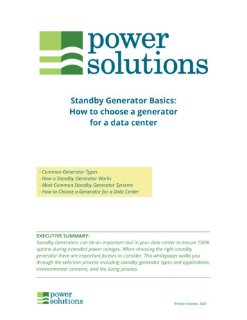
System Level DiagramDEC13-06
Power Supply Switching from a transformer to aToroidal transformer with a centertap to ground to power the wholedesign The center tap creates a negativevoltage that is needed for thenegative side of the biphasic pulse 12V AC power supply used for thearduino Using two smaller toroidaltransformers to power the gatedriversDEC13-06
Energy Storage Using six 8200 uF capacitors Created a PCB to hold all ofthe capacitors together The PCB contains adischarging relay unit Three capacitors used foreach side of the pulse;positive and negative sidesDEC13-06
Initial Gate Drive Circuit First semester designed anopamp circuit to drive theSwitching devices This circuit creates anadjustable DC voltage fromthe arduino PWM output Easy control by changingduty cycle of the PWMoutput Control can be done digitallywithout physical interactionwith deviceDEC13-06
Biphasic Gate Drive Circuit Switched to using DC-DCregulators to simplify circuit By using a SEPIC andinverting buck-boostconverters we can use onevoltage supply Can supply much greatercurrent to the switchingdevices 2A Arduino cannot controloutput only “read” it from itsanalog input. Requires a more complex pcbto use but have designed PCBfor switch regulators beforeDEC13-06
Biphasic Gate Drive Circuit When using high side switching it ishard to get an accurate Vgs This can be achieved using anisolated gate driver Isolation lets us use the devicessources as the virtual ground for anaccurate Vgs This circuit can be used inconjunction with the SEPICconverter, allowing us to still haveadjustable pulse parametersDEC13-06
MOSFET Board This board includes the main powerpath for the circuit Input voltage rectification andfiltering is done on this board Connections for the external caps. Traces between the caps andMOSFETs are as large as possible. Main switching MOSFETs are alsoon this board with connections tothe external gate delivers Building the PCB this way allowsfor design flexibilityDEC13-06
ArduinoTasks Handle the triggering of thepulses to the gate drivecircuits Discharge the capacitorsduring shutdownInputs Analog inputs for pulse widthand monitoring converteroutput Digital inputs for pulse triggerand capacitor dischargingOutputs Digital outputs for gate pulsesand capacitor dischargingDEC13-06
Enclosure Contains all of the componentsinto one box Provides no direct contactbetween user and device Will contain the input andoutputs on the outside of theenclosureDEC13-06
Simulations NI Multisim used forsimulations Used to simulate our circuitdesign before doing physicaltesting Ability to quickly modifycomponents and test multipleversions of the circuit Limited to only a selection ofcomponents that are accurateto real-world circuitryDEC13-06
Testing Bench testing for PCB boards Functionality verification High-wattage resistors withmakeshift coil for loadsDEC13-06
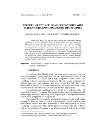
TestingNMOS pulsePMOS pulseDEC13-06
Risks & Challenges Physical harm to user Not finishing on time Not able to find the right parts forour design Parts not working as predicted PCB boards Grounding issues Team size cut in half after firstsemesterDEC13-06
Q &ADEC13-06
design The center tap creates a negative voltage that is needed for the negative side of the biphasic pulse 12V AC power supply used for the arduino Using two smaller toroida