Transcription
Video IP Coresfor Altera DE-Series BoardsFor Quartus II 11.01OverviewThe Altera University Program (UP) Video IP cores facilitate decoding, processing and display of video data. Theyare designed for use on Altera DE-series boards and work with on-board video-in and VGA chips, as well as Terasic’s5 megapixel CCD camera and LCD screen with touch panel daughtercards. This suite of IP cores comprises: a videodecoder, a VGA controller, eleven video-processing cores, two direct-memory-access (DMA) cores, a characterbuffer and two Video Image Processing (VIP) bridges. The video decoder converts raw video input from videoin chips on Altera DE2/DE2-70/DE2-115 boards, or Terasic’s 5 megapixel CCD camera, into packets that can beprocessed by the video-processing cores. The VGA controller core displays images by creating the timing signalsrequired by VGA compatible monitors attached to the VGA port on the DE-series board, or the Terasic LCD screenwith touch panel. The video-processing cores perform basic transformations on the video input, while the VIP bridgecores allow Altera VIP cores to be used together with Altera UP Video IP cores in more advanced applications. Thevideo DMA cores allow video data to be stored to and retrieved from memory. The character buffer core holdsASCII characters and converts them to a video stream, so that they can be displayed on a screen.The remainder of this manual is organized as follows: Section 2 gives a brief introduction of the cores and givesfour examples to assist designers using the video IP cores. Section 3, named Background, describes in detail howthe video IP core are connected, the format used to transfer data and the memory layout for stored video. A detaileddescription of all the UP video cores is given in Section 4.This manual assumes that the reader is familiar with the Altera SOPC Builder tool and how to use it.2Getting StartedIn this section, the cores will be briefly described through the use of four examples. The examples use the VGAoutput and video input ports on the DE-series boards. All examples were created using SOPC Builder, and includea Nios II processor and a 16 KB on-chip memory as a base system.All of these examples are available in the IP cores directory, which is installed using the University Program DesignSuite package.2.1Basic Video Out: Character DisplayThe first example demonstrates how to display characters on a VGA-compatible screen that is attached to the VGAport on the DE-series board. In this example, we make use of the following four cores: the VGA controller, ClockSignals, Dual-Clock FIFO and Character Buffer for VGA Display.Altera Corporation - University ProgramMay 20111
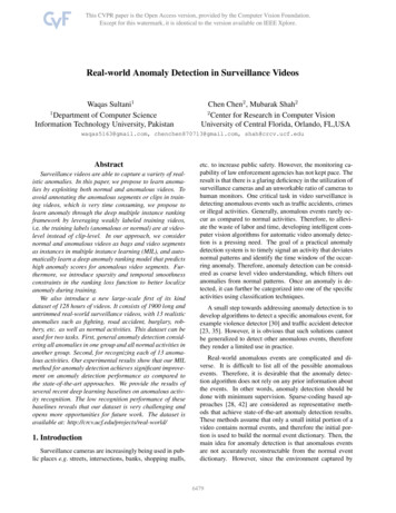
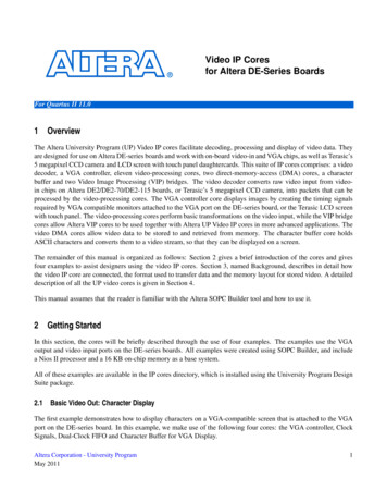
V IDEO IP C ORES FOR A LTERA DE-S ERIES B OARDSFor Quartus II 11.0In this example, drawing characters on the screen is implemented using the system shown in figure 1. To display acharacter on the screen, users must specify the character location to the Character Buffer IP core. Once specified,the character buffer renders an image of each character and sends it to the Dual-Clock (DC) FIFO core. The DCFifo buffers part of an image to be displayed on the screen until the VGA IP core is ready to display it. When theVGA cores is ready, the image will be displayed on the screen. It is important to note that in this example the VGAIP core and the character buffer operate at different clock frequencies. This is because the VGA IP Core needs torun at 25 MHz to properly display an image on the screen, while the Character Buffer was connected to the systemclock, which runs at 50 MHz. To allow both components to work together, the Clock Signals core generates theappropriate clocks, and the DC FIFO facilitates reliable communication between the two IP cores.Figure 1. Character display example’s SOPC Builder systemSample programs that run on this system are written in C. To run the example, do the following:1. Start the Altera Monitor Program software2. Connect the DE-series board, power it up and connect the USB cable between the board and the host computer3. Connect a VGA-compatible monitor to the VGA port on the DE-series board and power it up4. Open a project named "char buffer.ncf" in the example’s "IP Core Demos/DE2/DE2 Video SOPC Builder Demos/DE2 VGA Char Buffer/app software" directory5. Download the system onto the boards by clicking "Download SOPC Builder System" from the Actions menu6. Select "Compile and Load"7. Once the program is downloaded onto the system, click the Run button.2.2Basic Video Out: Pixel DisplayThe second example demonstrates how to display graphics on a VGA compatible screen that is attached to the VGAport on the DE-series board. In this example, we make use of the following cores: Pixel Buffer DMA Controller,SRAM/SSRAM controller, RGB resampler and Scaler.2Altera Corporation - University ProgramMay 2011
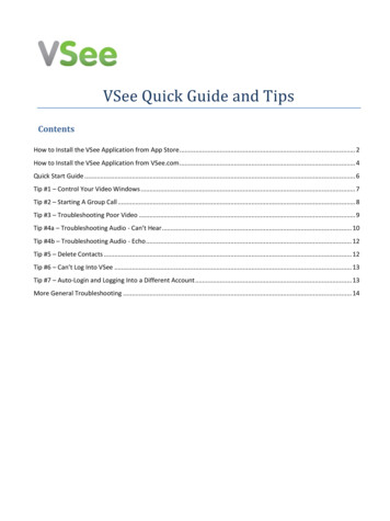
V IDEO IP C ORES FOR A LTERA DE-S ERIES B OARDSFor Quartus II 11.0The Pixel Buffer DMA Controller IP core produces video data for the VGA controller, similarly to the CharacterBuffer. Unlike the Character Buffer IP core which contains memory to serve as a buffer for ASCII characters, thePixel Buffer DMA Controller does not contain any memory. Instead, it has an Avalon memory-mapped interfacethat can be connected to any memory device in the SOPC Builder system. In this example, the SRAM/SSRAM willserve as memory for the pixel buffer. The Pixel Buffer DMA Controller reads the SRAM/SSRAM and sends theimage stored in memory to the VGA controller.The image stored in memory is configured to be 320 columns by 240 rows, with 16 bits representing the color ofeach pixel. This image must be converted into a format of 640 columns by 480 rows with 30 bits per pixel color,because this is the input format required by the VGA controller. The resampler and scaler IP cores are used toperform the conversion.First, the resampler core is used to change the number of bits needed to represent each pixel. This core extends the16-bit color value to 30 bits, while maintaining the image resolution of 320 by 240. Then the scaler core converts theresolution of the image from 320 by 240 to 640 by 480. To do this the core replicates each pixel 4 times, allowingthe scaler core to send a larger image to the VGA core. Please note that we still use the DC FIFO core to ensure thatthe scaler running at 50 MHz can reliably send the image data to the VGA core running at 25 MHz. The system usedin this example is shown in Figure 2. Note: that the example for the DE0 board uses on-chip memory and storesimages with a 80 x 60 resolution and 8-bit grayscale color space, since the board does not have an SRAM chip.Figure 2. Graphics display example’s SOPC Builder system.Sample programs that run on this system are written in C. To run the example, do the following:1. Start the Altera Monitor Program software2. Connect the DE-series board, power it up and connect the USB cable between the board and the host computer3. Connect a VGA-compatible monitor to the VGA port on the DE-series board and power it upAltera Corporation - University ProgramMay 20113
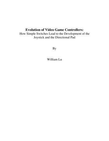
V IDEO IP C ORES FOR A LTERA DE-S ERIES B OARDSFor Quartus II 11.04. Open a project named "pixel buffer.ncf" in the example’s "IP Core Demos/DE2/DE2 Video SOPC Builder Demos/DE2 VGA Pixel Buffer/app software" directory5. Download the system onto the boards by clicking "Download SOPC Builder System" from the Actions menu6. Select "Compile and Load"7. Once the program is downloaded onto the system, click the Run button.2.3Video OutThe third example demonstrates how to merge the first two examples to display both characters and graphics simultaneously. In this example, we make use of the following cores: Pixel Buffer DMA Controller, SRAM/SSRAMcontroller, RGB resampler, Scaler, Character Buffer for VGA Display and Alpha Blender IP core.The Alpha Blender core combines two video streams into one. The blender has two parts for incoming video streams,named foreground and background. The foreground stream must contain alpha values, along with the regular pixelcolor values. The alpha values determine the ratio used to combine the foreground and background pixels. TheCharacter Buffer is used as the foreground and is set to automatically send alpha values with each pixel. The scaleris connected to the background port, so that the image resolution and color bits per pixel are identical for the twostream, which is required by the Alpha Blender. Once the video is combined it is sent to the Dual Clock FIFOand then to the VGA controller to be displayed. Figure 3 shows the SOPC Builder system that corresponds to thisexample.Figure 3. Graphics and character display example’s SOPC Builder system.Sample programs that run on this system are written in C. To run the example, do the following:1. Start the Altera Monitor Program software2. Connect the DE-series board, power it up and connect the USB cable between the board and the host computer4Altera Corporation - University ProgramMay 2011
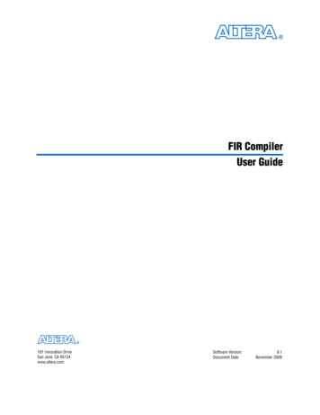
V IDEO IP C ORES FOR A LTERA DE-S ERIES B OARDSFor Quartus II 11.03. Connect a VGA-compatible monitor to the VGA port on the DE-series board and power it up4. Open a project named "char pixel.ncf" in the example’s "IP Core Demos/DE2/DE2 Video SOPC Builder Demos/DE2 VGA Both Buffers/app software" directory5. Download the system onto the boards by clicking "Download SOPC Builder System" from the Actions menu6. Select "Compile and Load"7. Once the program is downloaded onto the system, click the Run button.2.4Video InThe final example demonstrates how to decode incoming video data and output it using the VGA controller. Inthis example, we make use of the following cores: Pixel Buffer DMA Controller, SRAM/SSRAM controller, RGBresampler, Scaler, Character Buffer for VGA Display, Alpha Blender IP core and Audio and Video Configurtion IPcore, Video-In Decoder, Chroma resampler, Color Space Converter, Clipper, and Video-In DMA controller.The video analog-to-digital converter (ADC) chip on the DE2/DE2-70/DE2-115 boards converts video from thecomposite port and streams it into the FPGA. The Audio and Video Configurtion IP core initializes the ADC withthe appropriate settings for use with the UP Video IP cores. The Video-In Decoder IP core converts the videodata from the ADC into Avalon streaming packets and sends them to the video DMA controller. The video DMAcontroller writes the video stream to the pixel buffer (SRAM/SSRAM).The format of the video streamed from the Video-In Decoder is 720 columns by 244 rows with 16 bits per pixel inthe 4:2:2 YCrCb color space. The video must be converted into a format of 320 x 240 rows with 16 bits per pixel inthe RGB color space, because this is the format required by the pixel buffer. The Chroma Resampler, Color-SpaceConverter, RGB Resampler, Clipper and Scaler IP cores are used to perform the conversion.First, the Chroma Resampler converts the pixel from the 4:2:2 YCrCb to the 4:4:4 YCrCb formats, while maintainingthe frame resolution of 720 x 244. Then, the Color Space Converter converts between the 4:4:4 YCrCb and the 24-bitRGB color spaces. Next, the RGB Resampler converts the stream between the 24-bit RGB and 16-bit RGB formats.Then, the Clipper trims the stream from the 720 x 244 resolution to a 640 x 240 resolution by dropping the columnsand rows around the exterior of the frame. Lastly, the Scaler reduces the stream to 320 x 240 by dropping everyother pixel. Now that the video stream is in the correct format, the Video-In DMA Controller IP core transfers thestream to the SRAM/SSRAM. Figure 4 shows the SOPC Builder system that correspondes to this example.To run the example, do the following:1. Start the Altera Monitor Program software2. Connect the DE-series board, power it up and connect the USB cable between the board and the host computer3. Connect a VGA-compatible monitor to the VGA port on the DE-series board and power it up4. Connect a NTSC video source to the composite video port on the DE-series board and power it upAltera Corporation - University ProgramMay 20115
V IDEO IP C ORES FOR A LTERA DE-S ERIES B OARDSFor Quartus II 11.0Figure 4. Video in example’s SOPC Builder system.5. Open a project named "video in.ncf" in the example’s "IP Core Demos/DE2/DE2 Video SOPC Builder Demos/DE2 Video In/app software" directory6. Download the system onto the boards by clicking "Download SOPC Builder System" from the Actions menu3BackgroundIn this and the following sections, detailed descriptions of each IP core are given. This section contains informationcommon to most IP cores, while section 4 discussed each core individually.Video is produced by displaying frames (or images) in rapid succession. In a typical video, frames are displayedbetween 30 and 120 times per second. A frame is a two-dimensional array of pixels as depicted in Figure 5.The resolution of a frame is defined as the number of pixels in the x and y axes. An example resolution is 640 480,which has 640 pixels across the x axis and 480 pixels down the y axis, as shown in Figure 6. Therefore, each pixellocation in a frame can be identified by an (x,y) coordinate, with (0,0) being in the top-left corner.The next four sections describe how frames are mapped into memory, how they are transfered between the UP videoIP cores, and several formats that are used to represent individual pixels.6Altera Corporation - University ProgramMay 2011
V IDEO IP C ORES FOR A LTERA DE-S ERIES B OARDS012340x1.2For Quartus II 11.0.3yFigure 5. Video frame’s screen layout.0 1 2 3.639012.479Figure 6. A frame with a 640 480 resolution.3.1Memory Layout for Video FramesFrames are mapped to a memory’s address space in one of two modes. They are: Consecutive mode — the pixel addresses are consecutively laid out in the addressable space. For example, fora 640 480 resolution, the pixel at screen coordinate (0, 0) is at the offset 0, (1, 0) is at offest 1, . (639, 0) isat offset 639, (0, 1) is at offset 640, and so on.The address format is shown in Figure 7a. The k value, shown in the figure, is related to the frame’s resolutionas follows:k cei l (l og 2 (X Y ))where X and Y are the resolution in the x, y directions, respectively. For example, for a 640 480 resolution,shown in Figure 7b, we havek cei l (l og 2 (640 480)) 19 X-Y mode — the address contains x and y coordinates. The address format is shown in Figure 8a. The valuesof m and n , shown in the figure, are related to the frame’s resolution as follows:Altera Corporation - University ProgramMay 20117
V IDEO IP C ORES FOR A LTERA DE-S ERIES B OARDS31For Quartus II 11.00Consecutive Address (k bits)Not useda) Consecutive address format19 1831Not used0Consecutive Addressb) Consecutive address format for the 640 480 resolutionFigure 7. Address format for the Consecutive modem cei l (l og 2 X )n cei l (l og 2 Y )where X and Y are the resolution in the x, y directions, respectively. For example, for a 640 480 resolution,shown in Figure 8b, we havem cei l (l og 2 640) 10n cei l (l og 2 480) 9310Y coordinate (n bits)Not usedX coordinate (m bits)a) X-Y address format19 1831Not used10 9Y coordinate0X coordinateb) X-Y address format for the 640 480 resolutionFigure 8. Address format for the X-Y modeThe above addressing examples assume that the color of each pixel is represented with 8 bits. If the pixel color isrepresented by more than 8 bits, the addresses must be shifted to the left by the appropriate amount. Figure 9 showsgeneric addressing for 16-bit and 32-bit color pixel formats.3.2Video Stream Packet FormatThe UP video IP cores transfer frames using Avalon Streaming interfaces. Each packet in the stream represents oneframe of video data. The video frames are transfered one pixel at a time in row-major order. The first pixel, thetop-left pixel in the frame, is signalled by the start-of-packet bit in the Avalon Streaming interface. The last pixel,the bottom-left pixel in the frame, is signalled by the end-of-packet bit in the Avalon Streaming interface. Figure 10shows this streaming video packet representation.8Altera Corporation - University ProgramMay 2011
V IDEO IP C ORES FOR A LTERA DE-S ERIES B OARDS31Not usedFor Quartus II 11.01 00Pixel Addressesa) 16-bit data width3102 1Not usedPixel Addresses00b) 32-bit data widthFigure 9. Address format based on pixel’s data widthClockData ( k – 1 ) – 0(0,0)(1,0)(x-1,0) (x,0)(0,1)(1,1)(x,y)Start of PacketEnd of PacketData ValidFigure 10. Video frame’s streaming packet format.The format of each pixel in the packet depends on the video frame’s color space. The two color spaces used by theUP video IP cores are RGB and YCrCb, each having several different modes. Some of the video IP cores do notrequire knowledge of the specific color space and mode of the video stream it will process, but do require knowledgeof the number of bits per pixel. For these cores, it will be important to know the number of bits per color and thenumber of color planes of the color space and mode of the incoming packets.3.3RGB Color SpaceThe Red-Green-Blue (RGB) color space contains independent intensity values for each of the primary colors: red,green and blue. The range of the intensity for each color depends on the number of associated bits. The UP video IPcores can use the following RBG color ranges: 8-Bit RGB — This format uses 3 bits for red, and 3 bits for green and 2 bits for blue as shown in Figure 11.This mode is defined as 8 bits per color and one color plane.5 47R02 1GBFigure 11. 8-bit RGB Color Space.Altera Corporation - University ProgramMay 20119
V IDEO IP C ORES FOR A LTERA DE-S ERIES B OARDSFor Quartus II 11.0 9-bit RGB — This format uses 3 bits for each color as shown in Figure 12. This mode is defined as 3 bits percolor and three color planes.86 5R03 2GBFigure 12. 9-bit RGB Color Space. 16-Bit RGB — This format uses 5 bits for red, and 6 bits for green and 5 bits for blue as shown in Figure 13.This mode is defined as 16 bits per color and one color plane.1511 10R05 4GBFigure 13. 16-bit RGB Color Space. 24-bit RGB — This format uses 8 bits for each color as shown in Figure 14. This mode is defined as 8 bitsper color and three color planes.2316 15R08 7GBFigure 14. 24-bit RGB Color Space. 30-bit RGB — This format uses 10 bits for each color as shown in Figure 15. This mode is defined as 10 bitsper color and three color planes.2910 920 19RG0BFigure 15. 30-bit RGB Color Space. 16-bit RGBA — This format contains alpha values as well as RGB and uses 4 bits of each color as shown inFigure 16. This mode is defined as 4 bits per color and four color planes. 32-bit RGBA — This format contains alpha values as well as RGB and uses 8 bits of each color as shown inFigure 17. This mode is defined as 8 bits per color and four color planes.10Altera Corporation - University ProgramMay 2011
V IDEO IP C ORES FOR A LTERA DE-S ERIES B OARDS158 712 11A4 3GRFor Quartus II 11.00BFigure 16. 16-bit RGBA Color Space.3124 23A16 15R08 7GBFigure 17. 32-bit RGBA Color Space.39A10 920 1930 29BGR0Figure 18. 40-bit RGBA Color Space. 40-bit RGBA — This format contains alpha values as well as RGB and uses 10 bits of each color as shown inFigure 18. This mode is defined as 10 bits per color and four color planes. 8-Bit Grayscale — This is a special case of the RGB color space where are three colors have the same intensityand therefore produces shades of gray. Figure 19 shows to format of the 8-bit Grayscale data. This format isequivalent to YCrCb 4:0:0 color space. This mode is defined as 8 bits per color and one color plane.07GrayscaleFigure 19. 8-bit Grayscale RGB Color Space. Bayer Pattern — This is a special case of the RGB color space where each pixel has a value for only one ofthe three colors. The pattern of the colors in the frame is shown in 20. Figure 21 shows to format of the bayerpattern data. This mode is defined as 8 bits per color and one color plane.3.4YCrCb Color SpaceThe Luminance-Chrominance (YCrCb) color space contains information about the brightness (luminance or luma)and color (chrominance or chroma). The color is represented as two components, namely chrominance-red (Cr) andchrominance-blue (Cb). The UP video IP cores use 8 bits for each of Y, Cr and Cb. The following lists the YCrCbcolor space varieties used by the UP video IP cores: YCrCb 4:4:4 — This format is the normal YCrCb with all components as shown in Figure 22. This mode isAltera Corporation - University ProgramMay 201111
V IDEO IP C ORES FOR A LTERA DE-S ERIES B OARDSGRGRGBGBGBGRGRGRBGBGBGBGGBRG.BFor Quartus II 11.0.GFigure 20. Bayer pattern layout.07R07G07BFigure 21. Bayer Pattern RGB Color Space.defined as 8 bits per color and three color planes.2316 1508 7CrCbYFigure 22. YCrCb 4:4:4 Color Space. YCrCb 4:2:2 — This format has only half of the Cr and Cb components. Each consecutive pixel has alternatingCr or Cb components, with the first pixel in the frame starting with the Y and Cb pixel. Figure 23 shows twoconsecutive pixels for this format. This mode is defined as 8 bits per color and two color planes.150 158 7CbY08 7CrYFigure 23. YCrCb 4:2:2 Color Space.12Altera Corporation - University ProgramMay 2011
V IDEO IP C ORES FOR A LTERA DE-S ERIES B OARDSFor Quartus II 11.0 YCrCb 4:0:0 — This format only as the Y component as shown in Figure 24. This format is equivalent to8-Bit Grayscale RGB color space. This mode is defined as 8 bits per color and one color plane.07YFigure 24. YCrCb 4:0:0 Color Space.4Video IP Core DescriptionsIn this section, each IP core is described in detail.4.1Alpha BlenderThe Alpha Blender IP core combines two video streams into one. The two incoming streams, called foreground andbackground are blended together to create an output stream. The foreground must be in the 40-bit RGBA format,while the background must be in the 30-bit RGB format. The generated output stream is in the 30-bit RGB format.Figure 25 shows the block diagram of the core.Systemclock nstreamingsinkportmAvalonstreamingsourceportTo AvalonswitchfabricmBackgroundFigure 25. Alpha Blender core’s block diagram.The foreground and background streams are combined using the formula:C n α C f (1 α)C bC n is the new outgoing pixel color, α is a number between 0 and 1, C f is the incoming foreground pixel colors andAltera Corporation - University ProgramMay 201113
V IDEO IP C ORES FOR A LTERA DE-S ERIES B OARDSFor Quartus II 11.0C b is the incoming background pixel color. To blend the streams, this formula is computed three times, once of eachcolor plane, namely, the red, green and blue color planes.The key parameter in the blending process is α, which is provided as part of the foreground input stream. Theforeground input stream consists of a 30-bit RGB value, same as the background stream, and a 10-bit value A. Theα parameter is derived by dividing the unsigned 10-bit value A by 1023.The Alpha Blender has two modes of operation: simple and normal. In the simple mode, the alpha value is roundedto either 0 or 1, which simplifies the blending circuitry. In the normal mode, blending occurs exactly as describedabove. The mode is selected using the Alpha Blender SOPC Wizard as shown in Figure 26.Figure 26. Alpha Blender’s SOPC Builder’s wizard.4.2Bayer Pattern ResamplerThe Bayer Pattern Resampler converts a video stream from the Bayer Pattern format to the 24-bit RGB format. Fouradjacent pixels from the incoming stream are combined into one, as shown in Figure 27. The red and green valuesfrom the Bayer Pattern are copied to the new pixel. The averaged value of the two green values from the BayerPattern are used in the new pixel. The resulting outgoing stream will have a resolution with half the width and halfthe height of the incoming stream. Figure 28 shows the block diagram of the Bayer Pattern Resampler.GRGRGRG1RBGBGBGBG2GRGRGRBGBGBGR, (G1 G2)/2, BFigure 27. Bayer Pattern Resampler’s method of conversion.14Altera Corporation - University ProgramMay 2011
V IDEO IP C ORES FOR A LTERA DE-S ERIES B OARDSFor Quartus II 11.0Systemclock BayerPatternResamplerAvalonstreamingsourceportTo AvalonswitchfabricFigure 28. Bayer Pattern Resampler core’s block diagram.4.2.1Instantiating the Core in SOPC BuilderDesigners use the Bayer Pattern Resampler’s configuration wizard in the SOPC Builder to specify its settings. Thefollowing configurations are available and shown in Figure 29:Figure 29. Bayer Pattern Resampler’s SOPC Builder’s wizard. Video Source — Specifies the source of the Bayer Pattern, and by extension, it specifies the screen resolutionof the incoming stream.4.3Character Buffer for VGA DisplayThe Character Buffer for VGA Display renders ASCII characters into graphical representation for display. A program running on a Nios II processor can send ASCII character codes to the Character Buffer’s Avalon interface,named avalon char slave. The core stores the characters in its on-chip memory. The DMA controller reads theASCII characters from the on-chip memory and sends them to the character renderer. The renderer converts theAltera Corporation - University ProgramMay 201115
V IDEO IP C ORES FOR A LTERA DE-S ERIES B OARDSFor Quartus II 11.0ASCII characters into their graphical representation and send them out via an Avalon Streaming interface. Figure 30shows the block diagram of the character buffer.Systemclock urceportTo AvalonswitchfabricFigure 30. Character Buffer for VGA Display core’s block diagram.The Character Buffer supports one color mode, which is that characters are drawn in white with a transparentbackground.Upon initialization or reset, the Character Buffer sets all the characters to “space”, so no characters will be displayed.This “clear screen” operation can take up to 5000 clock cycles.The Character Buffer’s resolution is defined by the number of characters per line and the number of lines per screen.The Character Buffer supports one resolution per output device. For the on-board VGA DAC, the resolution is 80characters by 60 lines. For the LCD with touchscreen the resolution is 50 30. The core only supportes the X-Yaddressing mode, which is shown in Figure 31 for the two valid resolutions.317 613 12Not usedY coordinate0X coordinatea) X-Y address format for the 80 60 resolution31Not used6 5011 10Y coordinateX coordinateb) X-Y address format for the 50 30 resolutionFigure 31. Character address format16Altera Corporation - University ProgramMay 2011
V IDEO IP C ORES FOR A LTERA DE-S ERIES B OARDS4.3.1For Quartus II 11.0Instantiating the Core in SOPC BuilderDesigners use the Character Buffer’s configuration wizard in the SOPC Builder to specify the desired features. Thefollowing configurations are available and shown in Figure 32:Figure 32. Character Buffer for VGA Display’s SOPC Builder’s wizard. Video-Out Device — Specifies the device being used, and by extension the screen resolution. Enable Transparency — When enabled the output format is set to 40-bit RGBA. This setting must be enabledif the Character Buffer and Pixel Buffer are to be used together.4.3.2Software Programming ModelRegister MapDevice drivers control and communicate with the Character Buffer through two Avalon memory-mapped interfaces,named avalon control slave and avalon char slave. The avalon char slave interface has a byte data width forASCII characters and is addressed using the X-Y mode. The avalon control slave interface consists of the tworegisters shown in Table 1. The Control register provides the ability to clear the screen by writing to the R bit, whichis bit 16 of this register. The R bit remains set to 1 until all characters have been cleared, and then R is set to 0. TheResolution register, which is read-only, provides two values: the number of characters per line, in bits 15-0, and thenumber of lines per screen, in bits 31-16.Programming with the Character BufferThe Character Buffer is packaged with C-language functions that are accessible through the hardware abstractionlayer (HAL). These functions implement the basic operations that control the Character Buffer.To use the functions, the C code must include the statement:Altera Corporation - University ProgramMay 201117
V IDEO IP C ORES FOR A LTERA DE-S ERIES B OARDSFor Quartus II 11.0Table 1. Character Buffer register mapOffsetRegisterBit DescriptionR/Win bytesName31. . . 17 16 15. . . 00ControlRW(1)R(1)4ResolutionRLinesCharsNotes on Table 1:(1) Reserved. Read values are undefined. Write zero.#include "altera up avalon character buffer.h"alt up char buffer initPrototype:Include:Parameters:Description:void alt up char buffer init(alt up char buffer dev*char buffer) altera up avalon character buffer.h char buffer – struct for the character buffer deviceInitialize the name of thestructure.alt up char buffer open n:alt up char buffer dev* alt up char buffer open dev(constchar *name) altera up avalon character buffer.h name – the character buffer component name in SOPC Builder.The corresponding device structure, or NULL if the device is not foundOpens the character buffer device specified by name .alt up char buffer on:18int alt up char buffer draw(alt up char buffer dev*char buffer, unsigned char ch, unsigned int x,unsigned int y) altera up avalon character buffer.h ch – the character to drawx – the x coordinatey – the y coordinate0 for success, -1 for error (such as out of bounds)Draw a character at the location specified by (x, y) on the VGA monitorwith white color and transparent background.Altera Corporation - University ProgramMa
In this example, drawing characters on the screen is implemented using the system shown in figure1. To display a character on the screen, users must specify the character location to the Character Buffer IP core. Once specified, the character buffer renders an image of each character and sends it to the Dual-Clock