Transcription
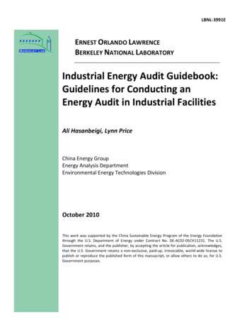
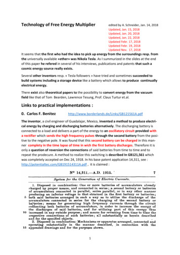
Technology of Free Energy Multiplieredited by A. Schneider, Jan. 14, 2018Updated, Jan. 15, 2018Updated, Jan. 20, 2018Updated, Jan. 22, 2018Updated Febr. 17, 2018Updated Febr. 19, 2018Updated Nov. 17, 2018It seems that the first who had the idea to pick up energy from the surroundings resp. fromthe universally available «ether» was Nikola Tesla. As I summurized in the slides at the endof this paper he refered in several of his interviews, publications and patents that such acosmic energy source really exists.Several other inventors resp. « Tesla followers » have tried and sometimes succeeded tobuild systems including a storage device like a battery which allows to produce continuallyelectrical energy.There exist also theoretical papers to the possibility to convert energy from the vacuumfield like that of Tom Bearden, Lawrence Tesung, Prof. Claus Turtur et.al.Links to practical implementations :0. Carlos F. dfThe inventor, a civil engineer of Guadalajar, Mexico, invented a method to produce electrical energy by charging and discharging batteries alternatively. The discharging battery isconnected to a load and delivers a part of the energy to an oscillatory circuit provided witha rectifier which sends the high frequency pulses through the second battery from the positive to the negative pole. It was found that this second battery can be charged in this manner complety in the time lapse of time in wich the first battery discharges. Therefore it isonly a question of reversion the connections of said batteries from time to time and torepeat the prodecure. A method to realize this switching is described In GB121,561 whichwas completely accepted on Dec 24, 1918. In his base patent application 14,311, see :http://potentialtec.com/GB191514311A.pdf , it is claimed :1
The basic circuit as printed in the patent application No 14,311 (GB) is reproduced here :2
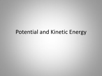
https://www.youtube.com/watch?time continue 12&v q1FyajzU3So 8 :17 (2.11 :58)Rick Friedrich explains inthis video how the invention of Carlos F. Benitezreally worked. Two seriallyconnected batteries 1 2with together 24 V are fedvia some loads to two parallely connected batteries3 4 (12 V) which are charged at the same time bythe flowing current. Aftersome time the chargingand loading batteries areinterchanged so that battery 3 4 are serially connected and batteries 1 2are parallely connected.And the current is flowingnow from battery 3 4 (24 V) via the load to battery 1 2 (12 V). Important is the oscillatorycircuit (below) which allows a faster and more effective charging of the batteries.Originally Carlos F. Benitez used capacitors instead of batteries, see at time 34 :50 in the linkgiven above.Also in this configuration the inventor emphasizes the need of an oscillatory circuit composed by a condensor, coils and a breaker. Evidently in this way it is possible to use resonanceenergy for recharging the parallelly connected right batteries from the serially connectedtwo left batteries completely and to use some remaining additonal energy for externalloads (lamps connected to line 36, see on the right). This load is transformed via transformer windings to left part (noted with 5) as a serial load to the left condenser.Much more can be learned by consulting the different videos of Rich Friedrich which canbe seen on the link mentioned above.3
1. Ronald Brandt/Bedini 080206/#.Wlm2za7iaM9At the Tesla Centennial Symposium in Colorado Springs, CO, on August, 11, 1984, John Bedinidemonstrated an inexpensive, cigar-box sized Tesla-type converter witch he had recently built.Throughout the demonstration, which lasted a full 24 hours during the symposium, a constant loadwas being drawn out of the system to do work, Nevertheless, the converter kept the nickel-cadmiumbatteries fully charged!The concept, witch had been originated by Nikola Tesla, was given to John Bedini by RonaldBrandt, who was a personal friend of Nikola Tesla. Brandt is reputed to have a similar converter which he has used for years without loosing the battery charge. Bedini presented theschematic diagram showing how to build the solid-state device, and then released copies ofthe schematic diagram.4
ery-switch#.Wlm3 a7iaM9Tesla used the fact that leadions are heavier thanelectrons. Every circuit, in ittransitory phase (from zerovolt to x volts) develops amuch higher voltage appliedon the negative side. Thisvoltage (pile-up of electronsmeeting the much heavierlead ions) is then normallydistributed in the circuit. Ifyou cut off the load and thesource battery, all thevoltage made by theelectrons gathered at thenegative side of the batteryyou want to charge, go inthat battery. If you do thatfrom 200 to 800 times persecond, you can charge thedestination battery (lead-acid) in a very short time (tens of minutes). By switching thebatteries between them, you restart the process and reload the source battery.Remark : According to Rick Friedrich it was found that such fast switching stresses theplates in the batteries to much which can result in batteries breack down.There is a company (Electrodyne Corporation) who tested this ensemblement and for threeyears they fueled many devices, with no unusual damage to the batteries. According to thelink : http://www.free-energy-info.co.uk/Chapt6.html Here you can read: The Electrodyne Corp. staff who experimented extensively with the Tesla Switch circuitry,found that when a battery was fully conditioned to used cold electricity, that a batterycould be disconnected, discharged independently to it’s full capacity, and then re-chargedcompletely in under one minute.That style of operation completely overcomes the objections to using battery banks topower household equipment of any power . This phenomenon is explained in more detailat the link: http://www.free-energy-info.com/Batteries.pdf5
THIS HAS THE SAME EFFECT AS IF A MUCHHIGHER VOLTAGE SOURCE HAD BEENCONNECTED TO THE BATTERY, CAUSING AMUCH GREATER RATE OF CHARGING.EFFECT ONLY LASTS FOR A FRACTION OF A SECOND, AND IF YOU ARE USING A DC CHARGINGSOURCE, IT ONLY OCCURS ONCE DURING THECHARGING SESSION.However, IF WE CHOOSE, WE CAN ARRANGEOUR CHARGING CIRCUIT TO DO THIS SWITCHON STYLE OF CHARGING THOUSANDS OFTIMES EACH SECOND.FOR EXAMPLE, LAWRENCE TSEUNG PRODUCEDA CHARGING SYSTEM WHICH IS A MODIFIEDJOULE THIEF CIRCUIT AND HE STATES THAT IT ISTEN TIMES MORE EFFECTIVE THAN ORDINARY CHARGING,see : http://www.free-energy-info.com/FLEET.pdfTHE CIRCUIT IS CALLED THE F.L.E.E.T. DEVICE WHERE F.L.E.E.T. STANDS FOR THE “FOREVERLEAD-OUT EXISTING ENERGY TRANSFORMER” EMPHASISING THAT THE EXTRA ENERGY HASNOT BEEN CREATED BUT INSTEAD HAS JUST BEEN DRAWN INTO THE CIRCUIT FROM THEENVIRONMENT WHERE IT ALREADY EXISTED.WHILE THE OUTER WINDING IS SHOWN HERE WITH THICKER WIRE OF A DIFFERENTCOLOUR, THIS IS ONLY TO MAKE THE DRAWING EASIER TO UNDERSTAND. IN REALITY, THEOUTER WINDING IS MADE WITH EXACTLY THE SAME WIRE AS THE INNER WINDING. BOTHWINDINGS GO ALL OF THE WAY AROUND THE TOROID.TOTAL AMOUNT OF WIRE NEEDED TO MAKE THE WINDINGS IS ABOUT 70 METRES AND SOIT IS NORMAL TO BUY A 100-METRE REEL OF THE TWIN-CORE WIRE AS THAT IS ENOUGH TOMAKE BOTH WINDINGS AND STILL HAVE SOME OVER FOR OTHER THINGS.6
TECHNICALLY MINDED PEOPLE, THE OUTPUTWAVEFORM LOOKS LIKE THIS : AND THERE AREABOUT 290,000 OF THOSE PULSES PER SECOND. ATAN EARLY STAGE, I DECIDED TO CONFIRM THAT FREEENERGY EXISTED, AND SO I BUILT A FLEET CIRCUIT INAN EVENING. I DECIDED TO USE TWO SMALL 12VOLT LEAD-ACID BATTERIES FOR THE TEST AND ICHOSE TO USE FOUR DIODES IN A BRIDGE RATHERTHAN JUST A SINGLE DIODE.I CHOSE TO USE TWO BATTERIES AND STAY AWAY FROM ANY FORM OF MAINS INPUT SOTHAT IT WOULD BE VERY CLEAR THAT NO CONVENTIONAL FORM OF ADDITIONAL POWERCOULD UPSET THE RESULTS.SO, I USED FLEET CIRCUIT POWERED BY ONE BATTERY TO CHARGE THE THE SECOND BATTERY. THEN I SWAPPED THE BATTERIES OVER AND USED THE SECOND BATTERY TO CHARGETHE FIRST. I DID THIS A COUPLE OF TIMES AND LET THE BATTERIES REST SO AS TO GET ARELIABLE READING FROM THEM. THE RESULT WAS A GENUINE GAIN OF REAL, USABLEPOWER IN BOTH BATTERIES.I CONSIDERED THAT RESULT TO SHOW THAT FREE-ENERGY IS MOST DEFINITELY A FACT, ESPECIALLY SINCE LEAD-ACID BATTERIES WASTE 50% OF ALL OF THE POWER THAT YOU FEEDINTO THEM WHEN CHARGING THEM, SO MY TEST HAD A CIRCUIT PERFORMANCE GREATERTHAN COP 2.THE EFFICIENCY OF THAT TEST WOULD PROBABLY HAVE BEEN VERY MUCH HIGHER IF I HADCHARGED TWO OR MORE BATTERIES CONNECTED IN SERIES. THE COIL USED WAS WOUNDON A PLASTIC PIPE OFFCUT WHICH WAS TO HAND AT THE TIME. IT WAS 8 INCHES INDIAMETER (200mm) AND 10mm X 12mm IN CROSS-SECTION AND THE WIRE WASSINGLESTRAND 6-AMP CAPACITY EQUIPMENT WIRE WHICH WAS AVAILABLE AT THE TIME.7
2. Tesla 4-battery system, Bedini 3-battery system, Ron Cole’s t62/Tesla Battery Switch 2.PGFED.pdfThe current flowing through the bulb can be arranged to be a charging current for anotherbattery. It can both light the bulb and charge another battery without needing any extracurrent: Here, the circuit is powered by battery 1 as before, but this time the current goes onto charge battery 2.Yes, battery 1 getsdischarged just asbefore, but the plusside is that battery 2is getting charged upall the time. The finalstep is to swap thebatteries over:And now, the newlycharged battery 2lights the bulb andcharges up battery 1again. Seem impossible? Well it isn’t.Nikola Tesla demonstrates this with his “4-battery switch” system where he chooses touse four identical batteries to implement this circuit:With 12-volt batteries asshown here, the bulb hasthe same 12 volts acrossit as it would have hadwith the single batteryshown in the first diagram, as batteries 1 and2 are wired “in series”to give 24 volts, whilebatteries 3 and 4 arewired “in parallel” togive 12 volts.Nikola Tesla arranged his circuit to swap the batteries over with 1 and 2 taking the place of 3and 4. He chose to do it in a slightly different way and he swapped the batteries over hundreds of times per second.8
The Weird stuff:There is another important factor involved in battery-charging circuits to be used with normal leadacid batteries and that is the practical detail of the materials involved.The charging process in this switching circuit is carried out by electrons flowing down the connectingwire and into the battery. The electrons flowing along the outer surface of the wire, move veryrapidly indeed.The main current inside the battery is carried by the charged ions inside the lead plates inside thebattery. These ions are hundreds of thousands of times heavier than the electrons. This doesn’tmatter at all once the ions get moving, but in the initial split second before the ions get going, theincoming electrons pile up like in a traffic jam tail-back.This pile-up of electrons pushes up the voltage on the terminal of the battery, well above thenominal battery voltage, and so the charging starts off with a high-voltage, high-current pulse intothe battery.This is not normally noticed when using a standard mains-powered battery charger, as switch-ononly occurs once during the whole charging process.In the Tesla switch shown here, and in the Bedini circuits shown earlier, this is not the case. Thecircuit takes advantage of this difference in momentum between the electrons and the lead ions, anduses it repeatedly to great advantage.The technique is to use very short duration pulses all the time. If the pulses are short enough, thevoltage and current drive into the receiving battery is far greater than a quick glance at the circuitwould suggest. This is not magic, just common-sense characteristics of the materials being used inthis circuit.A person unfamiliar with these systems, seeing John Bedini’s many advanced circuits for the firsttime, might get the impression that they are just crude, roughly-built circuits. Nothing could befurther from the truth. John often uses mechanical switching because it gives very sharp switch-onand switch-off times. John is a complete master of this circuitry and knows exactly what he is doing.The Electrodyne Corporation tested the Tesla 4-battery circuit over a period of three years.They found that at the end of that period, the batteries did not show any unusual deterioration.The batteries used were ordinary lead acid batteries.The system operated lights, heaters, television sets, small motors and a 30-horsepower electricmotor.If the batteries were run down to a low level and then the circuit switch on with a load, the recharging of the batteries took place in under one minute.9
No heating was experienced during this rapid charging. Heat was only produced during dischargecycles. If left undisturbed, each battery would charge up to nearly 36 volts. Control circuitry wasdeveloped to prevent this over-charging.They used mechanical switching and stated that below 100 Hz there was not much advantage withthe circuit and above 800 Hz it could be dangerous.They didn’t mention why they consider that higher rates of switching could be dangerous. If weconsider what exactly is happening, perhaps we can work out why they said that. The chargingsituation is like thisAt Time “A” the switch closes, connecting a voltage source (battery, charged capacitor, or whatever)to a lead-acid battery. Electrons start flowing down the outside of the connecting wire.Being very light and having little obstruction, they move very fast indeed (the electrons inside thewire only move a few inches per hour as getting through the wire is difficult).All goes well until Time “B” when the leading electrons reach the lead plates inside the battery.Here, they have a problem, because the current flow through the plates is carried by lead ions.Lead ions are very good at carrying current, but it takes them a split second to get going due to theirweight. That split second is critical and it opens the door to free-energy.In that split second, the electrons pile up because they are still arriving down the wire at very highspeed. So, at Time “C” they have built up into a large body of electrons.This large body of electrons has the same effect as if there had been a sudden connection to a muchhigher voltage source capable of supplying a much higher current.This situation only lasts for a very short time, but it has three very important effects.10
-Firstly, at Time “D”, it drives a much larger current into the battery than could reasonablyexpected from the original voltage source.-Secondly, this effect alters the Zero-Point Energy field (the space-time continuum) in whichthe circuit is located, causing extra energy to flow into the circuit from the outsideenvironment. This is a bit like sunshine generating current flow in an electric solar panel, butinstead of visible sunshine, the energy flow is not visible to us.-Thirdly, the excess energy flows into the battery, charging it much more than would beexpected, and at the same time, some of the excess energy flows into the load, powering itas well. The load could be a lamp, a motor, an inverter, a pump, a drill, or whatever.Conclusion : Excess energy is collected from the environment and used to bothcharge the battery and at the same time, perform useful work.The old saying “you can’t have your cake and eat it” just does not hold in this situation as that isexactly what happens.Instead of the battery being run down from powering the load, the load gets powered and the battery gets charged up at the same time.This why, with this system, a discharged battery can be used to apparently run a motor. It worksbecause the plates in the discharged battery are made of lead which forms a bottleneck for theelectron flow, causing the environment to charge the battery and run the load at the same time.That is why you get what looks like the magical effect of a discharged battery appearing to power aload. In passing, the more discharged the battery, the faster it charges as the environment adjustsautomatically to the situation and feeds greater power into a flat battery. The environment hasunlimited power available for use.11
John Bedini who is expert in this field has had motors running continuously for three or more yearswith the battery never running down and the motor doing useful work all the time. Great battery?No, - great environment !!For the vital build up of excess electrons to take place, the switch closure has to be very sudden andvery effective. A thyristor or “SCR” is suitable for this as once it is started, it switches on rapidly andfully. Sound good so far?This is only the start. I suggest that the Tesla 4-battery switch circuit operated in the 100 Hz to 800Hz region operates in this way. This situation can be further enhanced by suddenly cutting off theelectron flow from the original voltage source while the excess electron pile-up is still in place. Thiscauses a sudden (very brief) further surge in the excess power, building up the voltage and currenteven further and increasing the battery charging and load powering drive.An even greater effect can be had if the next, short, sharp pulse is applied to the battery/load combination, just before the effect from the last pulse dies away. I suggest that this is the situationwhich the Electrodyne Corporation people encountered when the pulse rate went over the 800 Hzrate. I suggest that it is not so much a case that the battery and load could not take the power, butmore a case that the components which they were using were not rated high enough to carry thatlevel of power.They do mention that if they went further, that they found that some of their circuit componentsstarted failing through not having high enough ratings (notice that the output capacitors are rated at100 volts which is eight times the nominal battery voltage). This was hardly a problem, consideringthat they had 12-volt batteries operating happily at 36-volts if they wanted that. They ended upbuilding circuitry to hold the voltages down to a convenient level.To summarise the situation. The Tesla 4-battery switch appears to do the impossible through:1. Catching the current coming out of the load and using it to charge another battery instead ofwasting it.2. Providing very short, sharp, and rapid switching pulses which exploit the momentum of the leadions current flow.3. Pulling extra energy in from the local environment to both charge the batteries and power theload at the same time This leaves aside the possibility of two further gains available through veryprecise timing of the switching pulses (mainly to make the power available more easily and cheaplyhandled).So, it should be borne in mind that the practical issues involved in getting this circuit operatingeffectively are primarily about very fast, clean and welltimed switching. Stranded, high-currentrated wire will be helpful in getting the draw of excess energy into the circuit.Tesla has used four diodes to simplify the switching and reduce it to two On/Off switches plus twochangeover switches. Alternatively, six On/Off switches can be used.In the refered link :http://www.vems.hu/freeenergy/pajert62/Tesla Battery Switch 2.PGFED.pdfYou will find more details about a realized circuit is described.12
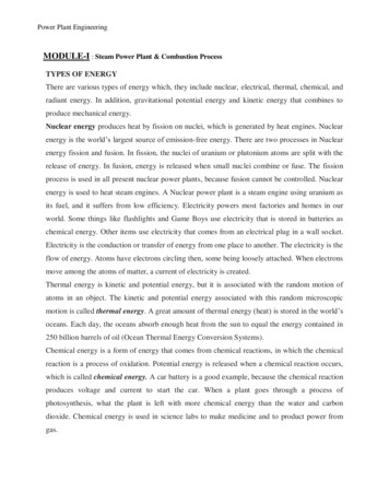
3. Carlos Ucrós Piedrahita : Free Energy Multiplier UCROSWebpages ish.htmhttps://kits-ucros.es.tl/Home---Inicio.htm Ucrós Multiplier Systemhttps://www.youtube.com/watch?v OUiKMm9IHCE1.2.3.4.5.Background. Two batteries 12 V 120 AhMiddle left : Pure Sine Wave InverterFront left: TransformerFront right: Schumacher Battery Charger 50 A, 12 VFront middle : 4 disconnect relais with white timer box for battery switchingThis system is build with only two batteries – not with 4 batteries as in the Tesla switch. This twobatteries are switched all 5 minutes from the inverter to the charger.During the 5 minutes the modified charger, which does load with current with superimposed rectangular pulses in the range of 900 Hz, is able to deliver 9 times or more the charge which is takenat the same time from the other battery which feeds the DC/AC-inverter.In the following 5 minutes the batteries are exchanged via timer controlled disconnect relais and thenext charging occurs on the decharged battery.See also : .pdfRemark :As it can be seen in the circuit schematics of Carlos Ucrós Piedrahitahe uses no special oscillatory circuit for the production of high frequency oscillations. But because standard battery chargers like thetype ABSAAR 12 V 22A/180A produce itself current pulses (and noDC-current) - see example in the oscilloscope picture – it seems thateven such « slow » pulsing with moderate slopes can trigger specialenergy effects as described in part 1 and 2.periode : 100 ms, current 45 A max.13
4. Panacea’s Documentation aboutMatthew Jones Tesla Switch, engineerGene, Tesla switch by mondrasek, a solidstate version by Jetijs ere we reproduce only the introductory text ofPeter Lindeman (we do know him personally):The following overview has been provided by PeterLindermann.« The original circuit was developed by Ronald Brandt. The 1983 date of the Brandt circuit pre-datesJohn Bedini’s work on this system. Ron's circuits used mechanical (as opposed to solid state)contractors as switches, but apparently worked quite well, as long as the contactors lasted.John was the first to adapt this circuit to solid-state switching, using the SG 1524 dual flip-flopfunctions and bipolar transistors as the switches.John has told me that his "cigar box" unit ran a small electric motor for more than 6 monthswithout discharging the batteries AT ALL. He also told me that the original working model wassmashed by a "guest" in his shop who was infuriated by its operation, while John was out of theroom. At this point, he decided not to rebuild it.I know John personally, and have no reason to doubt this report. Obviously, the voltage drops in thetransistors and diodes present a CONSTANT loss during operation, not to mention the energy dissipated at the load. Therefore, the system defies all standard explanations and energy use equations.The batteries apparently stay charged and run loads simultaneously for a reason that is notconventional.Since Ronald Brandt has run a car on this system, and John Bedini has run small motors onminiaturized version, it seems reasonable to assume it is worthy of more study by experimenters.It is recommended that you read a lengthy report; written by Eike Mueller, dated September 3,1984 entitled “EXPERIMENTS WITH A KROMREY AND A BRANDT-TESLA CONVERTER BUILT BY JOHNBEDINI (we have known Eike Mueller personally), see :http://www.tuks.nl/pdf/MUELLER EXPERIMENTS KROMREY BRANDT TESLA BEDINI.pdfWith Comments by Tom Bearden 1984 33 pages. Open source Rick Fredrick has this bookletavailable for sale on his web site. Or you can down load this from the energetic forum. Technicaldiscussion links and related links will be listed at the end of this course.5. Alexkor battery charging circuitThe Alexkor battery charging circuit is very effective, cheap and easy to build.See : System.pdfThe Alexkor circuit allows to charge a battery using twelve times less current than aconventional charger would. The circuit can charge lithium, NiCad or lead-acid batteries.14
6. Enlighted Technology#BREJU – Worlds most efficient battery page id 1241State of the art, High Tech, very high efficiency, Battery Charger/Quickener Rejuvenator. Fullyversatile and will charge almost any battery or battery pack. Will charge many batteries at once. Willcharge very fast compared to any other charger with the same amount of power input.Tested as high as 1.86 COP (186% efficiency) . Averages very close to 100% efficiency. For those whothink over-unity is impossible, you need to research heat pumps. These average a COP of 1.5 and ashigh as self-running (infinity). The extra energy comes from ambient. sometimes Charging circuittested as high as 300% in some tests (3x over unity).All other chargers that we tested averaged less then 50% efficient (0.5 COP)Summary of COP-values with pulse charged batteries0. Carlos F. Benitez – According to his patent GB121,561 he was able to fully charge a decharged battery bank in one ceratin time periode when an energy amount of 1/6 of the chargedbattery bank was used to recharage the decharged battery bank in the same time period.Therefore the COP was 6 :1.1. Ron Brandt/Bedini converter Electrodyne converter: COP not known but the systemshave been in use with loads running continously for days, months and years. The estimatedCOP was at least. 2 :1 or more2. Tesla 4-battery system, Bedini 3-battery system, Ron Cole’s 1-battery systemNo COP known, but continously running confirmed.3. Carlos Ucrós Piedrahita : Free Energy Multiplier UCROSInventor claims to have reached a COP of 9 :1 (905 to 10%)4. Panacea’s Documentation about Matthew Jones Tesla Switch, engineer Gene, Tesla switchby mondrasek, a solid state version by Jetijs etc.No COP given but the batteries apparently stay charged and run loads simultaneously5. Alexkor battery charging cicuitCOP was 12 :16. Enligthed TechnologyCOP 1,86 up to COP 3 :1Comments :A standard system of batteries, inverters, chargers if driven continously in a closed circle withoutadditional loads would result in the decharging of the batteries after some time because the totalCOP is much lower than 1. If you consider the losses in the inverter, the charger, the cablings and thebatteries you will get an overall efficiency of some 50% or a COP of 0,5 :1.Only if you are using the special effect of pulse charging – as explained in sections 1 to 6 andexspecially in the theoreticl paper of Dr. Cyril Smith you can get COP 1 or CP 1.15
Already when you can realize a COP of 2 :1 you are 4 times better then in the case of charging withcontinous current. If e.g. weg et 5 kW on the inverter output we feed 2,5 kW back via loader tot hebatteries and have 2,5 kW «free» to be used by the load.But when we discuss a COP 9 :1 as Carlos Ucrós has realized (according to this website) then we candeliver e.g. 4,44 kW to the load, 0,56 kW to the charger which is 1/9 of the of the total 5 kW whichthe inverter generates (which an efficiency of about 95%).If the inverter consumes 4,8 kW at 12 V, this correponds to a current of 400 A. With a COP 9 :1 itcan be assumed that the charger produces also 400 A pulses but with a pulse-pause ratio of 1:9 at afrequency of some 900 Hz. This large amount of down-up slopes of the pulses generates a fast electron flow and helps to charge the battery much faster compared with DC-current. The net powerneeded of the charger on the primary site is 4,8 kW/9 0,53 kW. But the actual values may differbecause we have also to consider the ohmic losses in different component and the wires.7. Special considerations by Rick Friedrich to Tesla-Switch-SystemsAs it is written in https://www.youtube.com/watch?time continue 12&v q1FyajzU3SoBedini himself has known that some circuit designs which are not recommended and caneven ruin the batteries. This is also the case with the traditional Tesla Switch which Bedinihas presented at the 1984 Tesla Symposium. According to Rick Friedrich it was Carlo Benitezwho has developped 100 years ago the real (working) Tesla Switch.In his video: https://www.youtube.com/watch?time continue 12&v q1FyajzU3So heemphasized several times that in fact the Bedini Tesla Switch caused a lot of problems (1:32).Lot of people wasted their time and money (1:42) and ruined their batteries (18:55). Thetype of Tesla Switch which Beini promoted actually destructed the batteries (2:25) as it didthe Watson machine (22:54). The principal of the Tesla Switch (or Brandt) with two batteriesin series and two in parallel war not invented by Bedini but 100 years before by Carlos F.Benitez (5:47). Carlos switched the batteries very slowly (7:53).Also the Bedini Tesla Switch Solar Amplifier had some serious failures (27:19). The switchingwas to fast and stressed the batteries.16
When you are switching to fast from the charging to the loading process the metal in thebatteries is to much stressed (32:01).8. Simplified battery charging circuitsRick Friedrich has published some papers where he has shown that even with a fewelectronic components it is possible to stimulate the special ‘’super-‘’charging behaviour ofbatteries.In his elaboration : http://www.r-charge.net/Free-Energy ep 56.html he desribes under thetitle «Selfish Unthankful Circuits or Loving Giving Paths. The Road to True Liberty» see also the video: https://youtu.be/SE-AiC9yiFc from Febr. 17, 2016, - that he has succeeded to present his final work on the subject of Free Energy and which may be part of a chapter in an upcoming book This is an attempt to show the world in the simplest way how tohave all the power they need in 4 different steps.17
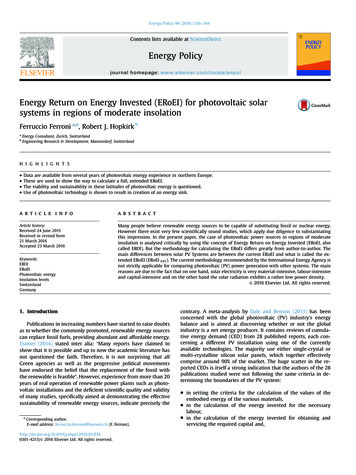
Open looping and transfering duplicate energy to another load beyond itselfOpen loop transfer of energyThis circuit shows how the energy inthe left battery can be mirrrored inthe right battery like an echo in theimpulse. Evidently the energy storedin the left battery is not wasted butgiven away to another. It is also possible to feed additional energy fromthe right battery to a load.The key element is an inductivitywhich is switched fast enough onand off and generates high voltagespikes and currents which are feededvia a diode to the positive pole ofsecond serially coupled battery.Close looping the duplicate energy back upon itselfClosed loop
The concept, witch had been originated by Nikola Tesla, was given to John Bedini by Ronald Brandt, who was a personal friend of Nikola Tesla. Brandt is reputed to have a similar con-verter which he has used for years without loosing