Transcription
hellocinu@gmail.com
Circuit AnalysisDemystified
Demystified SeriesAccounting DemystifiedAdvanced Calculus DemystifiedAdvanced Physics DemystifiedAdvanced Statistics DemystifiedAlgebra DemystifiedAlternative Energy DemystifiedAnatomy Demystifiedasp.net 2.0 DemystifiedAstronomy DemystifiedAudio DemystifiedBiology DemystifiedBiotechnology DemystifiedBusiness Calculus DemystifiedBusiness Math DemystifiedBusiness Statistics DemystifiedC DemystifiedCalculus DemystifiedChemistry DemystifiedCircuit Analysis DemystifiedCollege Algebra DemystifiedCorporate Finance DemystifiedDatabases DemystifiedData Structures DemystifiedDifferential Equations DemystifiedDigital Electronics DemystifiedEarth Science DemystifiedElectricity DemystifiedElectronics DemystifiedEngineering Statistics DemystifiedEnvironmental Science DemystifiedEveryday Math DemystifiedFertility DemystifiedFinancial Planning DemystifiedForensics DemystifiedFrench DemystifiedGenetics DemystifiedGeometry DemystifiedGerman DemystifiedHome Networking DemystifiedInvesting DemystifiedItalian DemystifiedJava DemystifiedJavaScript DemystifiedLean Six Sigma DemystifiedLinear Algebra DemystifiedMacroeconomics DemystifiedManagement Accounting DemystifiedMath Proofs DemystifiedMath Word Problems DemystifiedrMATLAB DemystifiedMedical Billing and CodingDemystifiedMedical Terminology DemystifiedMeteorology DemystifiedMicrobiology DemystifiedMicroeconomics DemystifiedNanotechnology DemystifiedNurse Management DemystifiedOOP DemystifiedOptions DemystifiedOrganic Chemistry DemystifiedPersonal Computing DemystifiedPharmacology DemystifiedPhysics DemystifiedPhysiology DemystifiedPre-Algebra DemystifiedPrecalculus DemystifiedProbability DemystifiedProject Management DemystifiedPsychology DemystifiedQuality Management DemystifiedQuantum Mechanics DemystifiedReal Estate Math DemystifiedRelativity DemystifiedRobotics DemystifiedSales Management DemystifiedSignals and Systems DemystifiedSix Sigma DemystifiedSpanish Demystifiedsql DemystifiedStatics and Dynamics DemystifiedStatistics DemystifiedTechnical Analysis DemystifiedTechnical Math DemystifiedTrigonometry Demystifieduml DemystifiedVisual Basic 2005 DemystifiedVisual C# 2005 DemystifiedVitamins and Minerals Demystifiedxml Demystified
Circuit AnalysisDemystifiedDavid McMahonNew YorkChicago San Francisco Lisbon London MadridMexico City Milan New Delhi San Juan SeoulSingapore Sydney Toronto
Copyright 2008 by The McGraw-Hill Companies, Inc. All rights reserved. Manufactured in the United States of America. Exceptas permitted under the United States Copyright Act of 1976, no part of this publication may be reproduced or distributed in anyform or by any means, or stored in a database or retrieval system, without the prior written permission of the publisher.0-07-151086-9The material in this eBook also appears in the print version of this title: 0-07-148898-7.All trademarks are trademarks of their respective owners. Rather than put a trademark symbol after every occurrence of atrademarked name, we use names in an editorial fashion only, and to the benefit of the trademark owner, with no intention ofinfringement of the trademark. Where such designations appear in this book, they have been printed with initial caps.McGraw-Hill eBooks are available at special quantity discounts to use as premiums and sales promotions, or for use in corporatetraining programs. For more information, please contact George Hoare, Special Sales, at george hoare@mcgraw-hill.com or (212)904-4069.TERMS OF USEThis is a copyrighted work and The McGraw-Hill Companies, Inc. (“McGraw-Hill”) and its licensors reserve all rights in and tothe work. Use of this work is subject to these terms. Except as permitted under the Copyright Act of 1976 and the right to store andretrieve one copy of the work, you may not decompile, disassemble, reverse engineer, reproduce, modify, create derivativeworksbased upon, transmit, distribute, disseminate, sell, publish or sublicense the work or any part of it without McGraw-Hill’s priorconsent. You may use the work for your own noncommercial and personal use; any other use of the work is strictly prohibited. Yourright to use the work may be terminated if you fail to comply with these terms.THE WORK IS PROVIDED “AS IS.” McGRAW-HILL AND ITS LICENSORS MAKE NO GUARANTEES OR WARRANTIESAS TO THE ACCURACY, ADEQUACY OR COMPLETENESS OF OR RESULTS TO BE OBTAINED FROM USING THEWORK, INCLUDING ANY INFORMATION THAT CAN BE ACCESSED THROUGH THE WORK VIA HYPERLINK OROTHERWISE, AND EXPRESSLY DISCLAIM ANY WARRANTY, EXPRESS OR IMPLIED, INCLUDING BUT NOTLIMITED TO IMPLIED WARRANTIES OF MERCHANTABILITY OR FITNESS FOR A PARTICULAR PURPOSE.McGraw-Hill and its licensors do not warrant or guarantee that the functions contained in the work will meet your requirements orthat its operation will be uninterrupted or error free. Neither McGraw-Hill nor its licensors shall be liable to you or anyone else forany inaccuracy, error or omission, regardless of cause, in the work or for any damages resulting therefrom. McGraw-Hill has noresponsibility for the content of any information accessed through the work. Under no circumstances shall McGraw-Hill and/or itslicensors be liable for any indirect, incidental, special, punitive, consequential or similar damages that result from the use of orinability to use the work, even if any of them has been advised of the possibility of such damages. This limitation of liability shallapply to any claim or cause whatsoever whether such claim or cause arises in contract, tort or otherwise.DOI: 10.1036/0071488987
ProfessionalWant to learn more?We hope you enjoy thisMcGraw-Hill eBook! Ifyou’d like more information about this book,its author, or related books and websites,please click here.
ABOUT THE AUTHORDavid McMahon is a physicist and researcher at a national laboratory. He isthe author of Linear Algebra Demystified, Quantum Mechanics Demystified,Relativity Demystified, Signals and Systems Demystified, Statics and DynamicsDemystified, and MATLAB r Demystified.Copyright 2008 by The McGraw-Hill Companies, Inc. Click here for terms of use.
This page intentionally left blank
For more information about this title, click hereCONTENTSPrefaceAcknowledgmentsxiiixvCHAPTER 1An Introduction to Circuit AnalysisWhat Is Circuit Analysis?Electric CurrentCurrent ArrowsVoltageTime Varying Voltage and Voltage SourcesDependent Voltage SourcesCurrent SourcesOpen and Short CircuitsPowerConservation of EnergySummaryQuiz1229111316161819222323CHAPTER 2Kirchhoff’s Laws and ResistanceBranches, Nodes, and LoopsKirchhoff’s Current LawKirchhoff’s Voltage LawThe ResistorPower in a ResistorCircuit Analysis with Resistors25252628313334
viiiCircuit Analysis DemystifiedRoot Mean Square (RMS) ValuesVoltage and Current DividersMore ExamplesSummaryQuiz3741465354Thevenin’s and Norton’s TheoremsThevenin’s TheoremStep One: Disconnect the Outside NetworkStep Two: Set Independent Sources to ZeroStep Three: Measure the Resistance atTerminals A and BSeries and Parallel CircuitsBack to Thevenin’s TheoremThevenin’s Theorem Using the Karni MethodNorton’s Theorem and Norton EquivalentCircuitsSummaryQuiz58596061CHAPTER 4Network TheoremsSuperpositionMillman’s TheoremQuiz86869396CHAPTER 5Delta–Wye Transformations and BridgeCircuitsDelta–Wye TransformationsBridge CircuitsQuiz9797101102Capacitance and InductanceThe CapacitorCapacitors in Parallel or SeriesVoltage–Current Relations in a CapacitorVoltage in Terms of Current103103104106107CHAPTER 3CHAPTER 661616777828484
ContentsixPower and Energy in the CapacitorTime Constants, Zero-Input Response, andFirst-Order RC CircuitsThe InductorInductors in Series and in ParallelEnergy in an InductorCurrent in an InductorZero-Input Analysis of First-Order RLCircuitsMutual InductanceZero-Input Response in an RL CircuitSecond-Order 30131CHAPTER 7The Phasor TransformBasics on Complex NumbersPolar RepresentationSinusoids and Complex NumbersSinusoidal SourcesLeading and LaggingEffective or RMS ValuesDynamic Elements and Sinusoidal SourcesThe Phasor TransformProperties of the Phasor TransformCircuit Analysis Using 9140142143147150151CHAPTER 8Frequency ResponseNatural FrequenciesThe Frequency Response of a CircuitFiltersSummaryQuiz152152156164169170
xCircuit Analysis DemystifiedCHAPTER 9Operational AmplifiersThe Noninverting AmplifierInverting AmplifierThe Summing AmplifierSummaryQuiz172173175176178178CHAPTER 10Sinusoidal Steady-State PowerCalculationsMaximum Power TransferInstantaneous PowerAverage and Reactive PowerThe RMS Value and Power CalculationsComplex PowerSummaryQuiz179179183185187194195196CHAPTER 11TransformersThe Dot ConventionSummaryQuiz197198200200CHAPTER 12Three-Phase CircuitsBalanced SequencesY LoadsSummaryQuiz202203204205205CHAPTER 13Network Analysis Using LaplaceTransformsThe Laplace TransformExponential OrderThe Inverse Laplace TransformAnalyzing Circuits Using Laplace TransformsConvolution206207210211214218
ContentsxiZero-State Response and the NetworkFunctionPoles and ZerosSummaryQuiz221224225226CHAPTER 14Circuit StabilityPoles and StabilityZero-Input Response StabilityBounded Input-Bounded Output StabilitySummaryQuiz228231236237239240CHAPTER 15Bode Plots and Butterworth FiltersAsymptotic Behavior of FunctionsCreating Bode PlotsBode Plot ExamplesFiltersButterworth FiltersQuiz241242244245252254259Final Exam260Quiz and Exam Solutions270References281Index283
This page intentionally left blank
PREFACECircuit analysis is one of the most important courses in electrical engineering,where students learn the basics of the field for the first time. Unfortunatelyit is also one of the most difficult courses that students face when attemptingto learn electrical engineering. At most universities it serves as a “weed out”course, where students not “cut out” for electrical engineering are shown the exit.A friend once referred to the course as “circuit paralysis” because he claimedto freeze up during the exams.The purpose of this book is to make learning circuit analysis easier. It canfunction as a supplement to just about any electric circuits book and it will serveas a tutorial for just about any circuit analysis class. If you are having troublewith electrical engineering because the books are too difficult or the professoris too hard to understand, this text will help you.This book explains concepts in a clear, matter-of-fact style and then usessolved examples to illustrate how each concept is applied. Quizzes at the endof each chapter include questions similar to the questions solved in the book,allowing you to practice what you have learned. The answer to each quiz questionis provided at the end of the book. In addition, a final exam allows you to testyour overall knowledge.This book is designed to help students taking a one-year circuit analysis courseor professionals looking for a review. The first 10 chapters cover topics typicallydiscussed in a first-semester circuit analysis course, such as voltage and currenttheorems, Thevenin’s and Norton’s theorems, op amp circuits, capacitance andinductance, and phasor analysis of circuits.The remaining chapters cover more advanced topics typically left to a secondsemester course. These include Laplace transforms, filters, Bode plots, andcharacterization of circuit stability.If you use this book for self-study or as a supplement in your class you willfind it much easier to master circuit analysis.Copyright 2008 by The McGraw-Hill Companies, Inc. Click here for terms of use.
This page intentionally left blank
ACKNOWLEDGMENTSI would like to thank Rayjan Wilson for his thorough and thoughtful reviewof the manuscript. His insightful comments and detailed review were vital tomaking this book a success.Copyright 2008 by The McGraw-Hill Companies, Inc. Click here for terms of use.
This page intentionally left blank
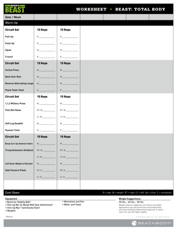
CHAPTER 1An Introduction toCircuit AnalysisAn electric circuit is an arrangement into a network of several connected electriccomponents. The components that we will be concerned with are two-terminalcomponents. This means that each component has two connection points orterminals that can be used to connect it with other components in the circuit.Each type of component will have its own symbol. This is illustrated in Fig. 1-1,where we indicate the terminals with two rounded ends or dots and use an emptybox to represent a generic electric component.There are several electric components but in this book our primary focus willbe on resistors, capacitors, inductors, and operational amplifiers. At this point,we won’t worry about what these components are. We will investigate each onein detail later in the book as the necessary theory is developed. In this chapterwe will lay down a few fundamentals. We begin by defining circuit analysis.Copyright 2008 by The McGraw-Hill Companies, Inc. Click here for terms of use.
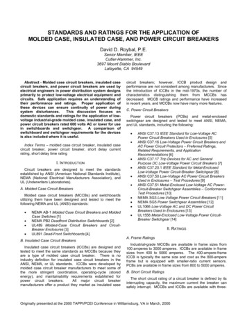
Circuit Analysis Demystified2TerminalTerminalSymbol for specificelectrical component.Fig. 1-1 A diagram of a generic two-terminal electric component.What Is Circuit Analysis?The main task of circuit analysis is to analyze the behavior of an electric circuitto see how it responds to a given input. The input could be a voltage or a current,or maybe some combination of voltages and currents. As you might imagine,electric components can be connected in many different ways. When analyzinga circuit, we may need to find the voltage across some component or the currentthrough another component for the given input. Or we may need to find thevoltage across a pair of output terminals connected to the circuit.So, in a nutshell, when we do circuit analysis we want to find out how theunique circuit we are given responds to a particular input. The response of thecircuit is the output. This concept is illustrated in Fig. 1-2.To begin our study of circuit analysis, we will need to define some basicquantities like current and voltage more precisely.Electric CurrentElectric charge is a fundamental property of subatomic particles. The amountof electric charge that a particle carries determines how it will interact withInput to circuitElectrical CircuitOutput or responseof circuitFig. 1-2 The task of circuit analysis is to find out what the output or response of anelectric circuit is to a given input, which may be a voltage or current.
CHAPTER 1An Introduction to Circuit Analysis3electric and magnetic fields. In the SI system, which we will use exclusively inthis book, the unit of charge is the coulomb. The symbol for a coulomb is C.An electron carries an electric charge given bycharge of single electron 1.6 10 19 C(1.1)The electric charge in an element or region can vary with time. We denoteelectric charge by q(t), where the t denotes that charge can be a function oftime.The flow of charge or motion of charged particles is called electric current.We denote electric current by the symbol i(t), where the t denotes that currentcan be a function of time. The SI unit for current is the ampere or amp, indicatedby the symbol A. One amp is equal to the flow of one coulomb per second1 A 1 C/s(1.2)Current is formally defined as the rate of change of charge with time. That is, itis given by the derivativei(t) dq(amperes)dt(1.3)EXAMPLE 1-1The charge in a wire is known to be q(t) 3t 2 6 C. Find the current.SOLUTIONUsing (1.3), we havei(t) dqd (3t 2 6) 6t AdtdtEXAMPLE 1-2Find the current that corresponds to each of the following functions of charge:(a) q(t) 10 cos 170πt mC(b) q(t) e 2t sin t µC(c) q(t) 4e t 3e5t CSOLUTIONIn each case, we apply (1.3) paying special attention to the units. In (a), wehave q(t) 10 cos 170π t mC. Since the charge is measured in millicoulombs
Circuit Analysis Demystified4or 10 3 C, the current will be given in milliamps, which is 10 3 A. Hencei(t) ddq(10 cos 170π t) 1700π sin 170π t mA dtdtIn (b), notice that the charge is expressed in terms of microcoulombs. Amicrocoulomb is 10 6 C, and the current will be expressed in microamps.Using the product rule for derivatives which states( f g) f g g fWe find that the current isdqd (e 2t sin t)dtdtdd (e 2t ) sin t e 2t (sin t)dtdti(t) 2e 2t sin t e 2t cos t e 2t ( 2 sin t cos t) µAFinally, in (c), the charge is given in coulombs, and therefore, the current willbe given in amps. We havei(t) ddq (4e t 3e5t ) 4e t 15e5t AdtdtLooking at (1.3), it should be apparent that, given the current flowing pastsome point P, we can integrate to find the total charge that has passed throughthe point as a function of time. Specifically, let’s assume we seek the total chargethat passes in a certain interval that we define as a t b. Then given i(t), thecharge q is given by q bi(t) dt(1.4)aEXAMPLE 1-3The current flowing through a circuit element is given by i(t) 8t 3 mA.How much charge passed through the element between t 0 and t 2 s?
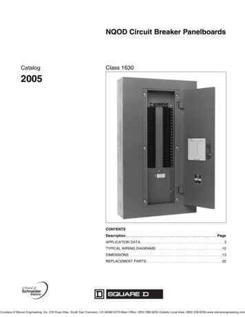
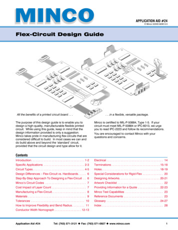
CHAPTER 1An Introduction to Circuit Analysis5i (A)20t (ms)013Fig. 1-3 A plot of the current flowing past some point in a circuit.SOLUTIONWe can find the total charge that passed through the element by using (1.4). Wehave q ab i(t) dt 2 (8t 3) dt 8002 t dt 3 2 2 4t 2 0 3t 0 (16 6) mC 22 mC2dt0EXAMPLE 1-4The current flowing past some point is shown in Fig. 1-3. Find the total chargethat passes through the point.SOLUTIONFirst, notice that time is given in milliseconds and current is given in amps.Looking at the definition of the amp (1.2), we could write the coulomb as1 C 1 A-sLooking at the definition (1.4), the integrand is the product of current andtime. In this example, as we stated above, current is given in amps and time isgiven in ms 1 10 3 s. Therefore the final answer should be expressed as(1 A) (1 ms) 1 10 3 A-s 10 3 C 1 mCNow let’s look at the plot. It is divided into two regions characterized by adifferent range of time. We can find the total charge that flows past the point byfinding the total charge that flows in each range and then adding the two chargestogether. We call the total charge that flows past the point for 0 t 1 q1 andwe denote the total charge that flows past the point for 1 t 3 q2 . Once we
Circuit Analysis Demystified6calculate these quantities, our answer will beq q1 q2(1.5)The first region is defined for 0 t 1 where the current takes the form ofa straight line with a slopei(t) at b Awhere a and b are constants. We know the value of the current at two pointsi(0) 0 A,i(1) 20 AFirst, using i(0) 0 together with i(t) at b tells us that b 0, so weknow the current must assume the form i(t) at A. Second, i(1) 20 A allowsus to determine the value of the constant a, from which we find that a 20.Therefore 1 120 1q1 i(t) dt 20t dt t 2 10 mC(1.6)2 000As an aside, what are the units of a? If i(t) at A then the product at mustbe given in amperes. Remembering that t is given in milliseconds[at] [a] [ms] A C/sC [a] ms-sThere are 10 3 s in a millisecond, therefore 3 C10 s10 3 CmCC[a] ms-sms-sms(ms)2(ms)2Notice how this is consistent with (1.6), where we integrate over 0 to 1 ms, andwe have a factor of time squared that cancels the time squared in the denominator of the units used for the constant a, leaving millicoulombs in the final result.Let’s finish the problem by examining the region defined by 1 ms t 3 ms.In this region, the current is a constant given by i(t) 20 A. The total chargethat passes is q2 13 3i(t) dt 201 3dt 20t 1 40 mC
CHAPTER 1An Introduction to Circuit Analysis7In conclusion, using (1.5) the total charge that passes the point isq 10 mC 40 mC 50 mCThe next example will be a little bit painful, but it will help us review somecalculus techniques that come up frequently in electrical engineering.EXAMPLE 1-5The current flowing through a circuit element is given by i(t) e 3t 16 sin 2tmA. How much charge passed through the element between t 0 and t 3 s?SOLUTIONWe can find the total charge that passed through the element by using (1.4). Wehave q ba i(t) dt 163e 3t (16 sin 2t) dt03e 3t sin 2t dt mC0We can do this problem using integration by parts. The integration-by-partsformula is dfdgdt(1.7)f (t) dt f (t)g(t) g(t)dtdtLooking at the integral in our problem, we letf (t) e 3t df 3e 3tdtThis means thatdg sin 2tdtUsing elementary integration we find that1g(t) cos 2t2
Circuit Analysis Demystified8So using (1.7), we have 316e 3 3 31 3t 3tsin 2tdt 16 e cos 2t e cos 2t dt022 0 3 3 3t e 3t cos 2t dt 8e cos 2t 0 24 3t00Now we have to apply integration by parts again on the second term. Usingthe same procedure where we make the identificationdg cos 2tdtWe find that 3e 3t0 3 31cos 2t dt e 3t sin 2t 0 22 3e 3t sin 2t dt0Hence 316e 3tsin 2t dt 8e0 8eNow we add 36 3t 52003 3cos 2t 24 0 3 3cos 2t 12e 3t sin 2t 360 3 3t03e 3t cos 2t dt0 3e 3t sin 2t dt0e 3t sin 2t dt to both sides. This gives the result 3 3e 3t sin 2t dt 8e 3t cos 2t 0 12e 3t sin 2t 0The right-hand side evaluates to 3 3 8e 3t cos 2t 0 12e 3t sin 2t 0 8e 9 cos 6 8 12e 9 sin 6 8Therefore 3 3 3 81 0.154e 3t sin 2t dt 8e 3t cos 2t 0 12e 3t sin 2t 0 52520
CHAPTER 1An Introduction to Circuit Analysis9i(t)Fig. 1-4 We indicate current in a circuit by drawing an arrow that points in thedirection of current flow.So the total charge is q 163e 3t sin 2t dt mC (16)(0.154) mC 2.461 mC0Current ArrowsWhen drawing an electric circuit, the direction of the current is indicated byan arrow. For example, in Fig. 1-4 we illustrate a current flowing to the rightthrough some circuit element.The flow of current can be defined by the flow of positive charge or the flowof negative charge. Even though we think of current physically as the flow ofelectrons through a wire, for instance, by convention in electrical engineeringwe measure current as the rate of flow of positive charge. Therefore A current arrow in a circuit diagram indicates the direction of flow ofpositive charge. A positive charge flow in one direction is equivalent to a negativecharge flow in the opposite direction.For example, consider the current shown flowing to the right in Fig. 1-4.Finding that i(t) 0 when we do our calculations means that positive chargesare flowing in the direction shown by the arrow. That is, i(t) 0 Positive charges flowing in direction of arrowNow suppose that when we do the calculations, we instead find that i(t) 0.This means that the positive charges are actually flowing in the direction oppositeto that indicated by the arrow. In this case we have the following situation:
10Circuit Analysis DemystifiedIf i(t) 0 Positive charges flowing in direction of arrow i(t) 0 Positive charges are flowing in direction opposite to the arrowSince the current in this case is calculated to be negative, this is equivalentto a positive current flowing in the opposite direction. That is, we reverse thedirection of the arrow to take i(t) to be positive.i(t) 0Let’s focus on this point for a minute by looking at some examples. Thismeans that a flow of 5 C/s to the right is the same as 5 C/s flowing to theleft. It also means that 7 A of negative charge flowing to the left is equivalentto 7 A of positive charge flowing to the right.EXAMPLE 1-6At a certain point P in a wire, 32 C/s flow to the right, while 8 C/s of negativecharge flow to the left. What is the net current in the wire?SOLUTIONBy convention we define current as the rate of flow of positive charge. Thecurrent that flows to the right in the wire isi R (t) 32 AThe current flowing to the left is negative chargei L (t) 8 ANow 8 A of negative charge flowing to the left is equivalent to 8 A of positivecharge flowing to the right. So the net current isi(t) i R (t) i L (t) 32 ( 8) 40 A
CHAPTER 1An Introduction to Circuit Analysis11Let’s combine the idea of positive charge flow with the representation ofcurrent in a circuit diagram with a little arrow, as in Fig. 1-4. With the conventionthat the arrow points in the direction of positive charge flow If the value of the current satisfies i(t) 0, then positive charges areflowing in the direction that the arrow points. If the value of the current satisfies i(t) 0, then the flow of positivecharge is in the direction opposite to that indicated by the arrow.Refer to Fig. 1-4 again. If we are told that i(t) 6 A, then this means that6 A of positive charge are flowing to the right in the circuit. On the other hand,if we are told that i(t) 3 A, then this means that 3 A of positive chargeare flowing to the left in the circuit. The negative sign means that the flowof positive charge is in the direction opposite to that indicated by the arrow.Hence, while the current arrow is to the right, since i(t) 3 A, which is lessthan zero, the positive charges are flowing to the left: 3Ai(t)i(t) 0 Positive charges are flowing in direction opposite to the arrowVoltageThe next part of the basic foundation we need to add to our toolkit for studyingelectric circuits is the concept of voltage. In short, voltage is the electric versionof potential energy, which is energy that has the potential to do work. The firstexample of potential energy that a student encounters is usually the potentialenergy of a mass m in a gravitational field g. If the mass m is at a height h withrespect to some reference point, then the potential energy isU mghThe gravitational potential energy has meaning only when it is thought of as apotential difference between two heights. If the mass falls from the upper heightto the lower height, it gains kinetic energy. The mass obtains the energy fromthe potential U. Recall from your studies of elementary physics that when usingSI units we measure energy in joules, which are indicated by the symbol J.
Circuit Analysis Demystified12Voltage is analogous to potential energy, and it is often referred to as thepotential difference between two points A and B in a circuit. The units ofvoltage are1 volt 1 joule/coulomb 1 V 1 J/C(1.8)In circuit analysis we usually indicate voltage as a function of time by writingv(t). The voltage between points A and B in a circuit is the amount of energyrequired to move a charge of 1 C from A to B. Voltage can be positive ornegative. When the voltage is positive, i.e., v(t) 0, we say that the path A–Bis a voltage drop. When a positive charge passes through a voltage drop, thecharge gains energy. This is because, if v(t) 0, the point A is at a higherpotential than the point B, in the same way that a point 100 m above the surfaceof the earth is at a higher potential than a point at sea level, since U mgh fora gravitational field.On the other hand, suppose that the voltage between two points A and B ina circuit is negative. In this case, we say that the path A–B is a voltage rise. Tomove a positive charge from A to B when the path is a voltage rise, we have tosupply energy. This is analogous to the energy you have to supply to lift a 50 lbweight from the ground to a spot on the shelf 5 ft higher.Voltage is formally defined asv dwVdq(1.9)where w is the work required to move the charge w across the potential difference.To find the energy acquired by a charge, we examine the units of voltage,which are given as joules per coulomb which is energy per charge. Thereforeto find the energy that a charge gains or loses when passing through a potentialdifference, we multiply the charge carried by the voltageE qV(1.10)EXAMPLE 1-7A 2 C charge and a 7 C charge pass through a potential difference of 3V and a potential difference of 2 V. Find the energy gained or lost by eachcharge.
CHAPTER 1An Introduction to Circuit Analysis13SOLUTIONWe apply (1.10). When the 2 C charge passes through the potential differenceof 3 VE q V (2 C) (3 V) (2 C) (3 J/C) 6 JThis means that 6 J of energy had to be added to the system to move thecharge through the potential difference. When the charge passes through thepotential difference of 2 VE q V (2 C) ( 2 V) (2 C) ( 2 J/C) 4 JSince the energy is negative, the charge acquired or gained 4 J of energy whenpassing through the potential difference. Now let’s consider the 7 C charge.When this charge passes through the first potential differenceE q V ( 7 C) (3 V) ( 7 C) (3 J/C) 21 JThis charge acquired 21 J of energy moving through the 7 V potential. In thesecond caseE q V ( 7 C) ( 2 V) ( 7 C) ( 2 J/C) 14 JThe energy is positive, indicating that the charge lost energy moving throughthe potential difference.Time Varying Voltage and Voltage SourcesWe are all used to the terms DC and AC and have seen constant voltage sourceslike 12 V for a battery. Although we may be used to 9 and 12 V batteries, in manysituations the voltage in a circuit will vary with time. We have already indicatedthis by writing voltage as a time-dependent function v(t). Of particular interestare voltages that oscillate sinusoidally. For example, in the United States, thevoltage in a household outlet oscillates between 170 and 170 V according tov(t) 170 sin 377t(1.11)In general, a sinusoidal function can be written asf (t) A sin ωt(1.12)
Circuit Analysis Demystified14We call A the amplitude of the sine wave. The units of the amplitude dependon the type of wave that is oscillating. In (1.11), the amplitude is A 170 V. Inshort, the amplitude is the maximum height that the function attains above theorigin.The angular frequency of the sine wave is given by ω. This is related to thefrequency, which is denoted by ν using the relationω 2π ν(1.13)Angular frequency is measured in radians per second. The frequency ν tellsus the number of cycles per second in the wave. A cycle is a complete repetitionof the waveform; therefore, the number of cycles per second is the number oftimes the waveform repeats in one second. We can abbreviate cycles per secondby writing cps and note that a cycle per second is
Digital Electronics Demystified Earth Science Demystified Electricity Demystified Electronics Demystified Engineering Statistics Demystified . with electrical engineering because the books are too difficult or the professor is too hard to understand, this text will help you. This bo