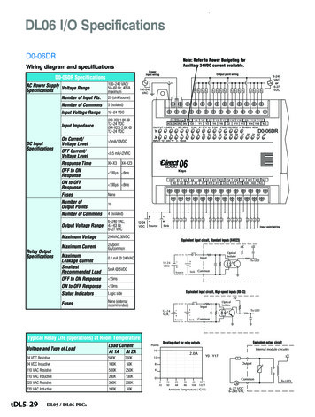
Transcription
Basics of PLCsA quickSTEP Online Course Siemens Industry, Inc.www.usa.siemens.com/step
TrademarksSiemens and SIMATIC are trademarks of Siemens AG. Other trademarks are the property of theirrespective owners. Siemens Industry, Inc. 2016Page 1-2
Course TopicsWelcome to Basics of PLCs. This course coversthe following topics:Chapter 1 - Introduction Overview Basic ConceptsChapter 2 - S7-1200 PLCs S7-1200 PLC Overview S7-1200 with Safety IntegratedChapter 3 - S7-1200 PLC Programming Programming Concepts LAD Programming Basics LAD Timers and CountersChapter 4 - Additional Information Additional S7-1200 Capabilities Additional ProductsIf you do not have an understanding of basicelectrical concepts, you should complete Basicsof Electricity before attempting this course. Siemens Industry, Inc. 2016Page 1-3
Course ObjectivesUpon completion of this course you will be able to Describe important number systems and data types used by Siemens PLCs. Identify the major components of a PLC and describe their functions. Describe the parts of a typical PLC scan. Define the terms “functional safety” and “failsafe.” Identify the key features of S7-1200 standard and failsafe CPU models. Identify the types of S7-1200 PLC signal and communication modules. Summarize the capabilities of TIA Portal. Summarize the capabilities of STEP 7 (TIA Portal). Describe what is meant by “security integrated.” List the programming languages available for S7-1200 PLCs. Describe the concept of modular programming and the types of program anddata blocks available for Siemens PLCs. Describe the operation of the most commonly used ladder diagramprogramming instructions. Describe what is meant by S7-1200 integrated technologies. Siemens Industry, Inc. 2016Page 1-4
SIMATIC S7-1200 PLCsAutomation solutions must be compact, scalable, and flexible. Siemens SIMATIC S7-1200 PLCs areavailable as standard and failsafe versions. In addition to helping you learn basic PLC concepts, thiscourse will help you understand the capabilities of S7-1200 PLCs, which can be optimally adapted toyour individual requirements with pluggable signal and communication boards and modules. Siemens Industry, Inc. 2016Page 1-5
SITRAIN Training for IndustryOnline Self-paced Learning – Programs with maximum flexibility so students can easily fitcourses into their busy schedulesVirtual Instructor-led Learning - Classroom lectures delivered in the convenience of yourhome or officeClassroom Learning - Expert and professional instructors, proven courseware, and qualityworkstations combine for the most effective classroom experience possible at your facility oroursHow-to Video Library - Quick, affordable, task-based learning options for a broad range ofautomation topics for training or purchaseSimulators - World-class simulation systems available for training or purchaseThis course also describes learning options available from the Siemens SITRAIN USA organization and ourglobal SITRAIN partners. For additional information: www.usa.siemens.com/sitrain Siemens Industry, Inc. 2016Page 1-6
Chapter 1 - IntroductionThis chapter covers the followingtopics: Overview Basic Concepts Siemens Industry, Inc. 2016Page 1-7
DefinitionA programmable logic controller (PLC), also referred to as aprogrammable controller, is a type of computer commonlyused in commercial and industrial control applications.PLCs differ from office computers in the types of tasks theyperform and the hardware and software they require toperform these tasks. While the specific applications varywidely, all PLCs monitor inputs and other variable values,make decisions based on a stored program, and controloutputs to automate a machine or process.There are many types of PLCs, and they vary significantlyin appearance and capabilities. Therefore, to keep thiscourse simple, the examples used focus primarily onSiemens SIMATIC S7-1200 basic controllers. AlthoughS7 1200 PLCs offer basic automation solutions, they alsohave many advanced features, and learning about S7-1200PLCs will help you gain a good understanding of PLCcapabilities. Siemens Industry, Inc. 2016Page 1-8
Basic PLC OperationThe basic components of a PLC include input signal modules, acentral processing unit (CPU), output signal modules, and aprogramming device. The types of input and output signalmodules used by a PLC depend upon the types of input andoutput devices used.Input signal modules convert the signals provided by input devicesinto logic signals that can be used by the CPU.The CPU uses the values of inputs, outputs, and other variablesas it executes the user program stored in its memory. The CPUthen sends signals to update the statuses of outputs.Output signal modules convert signals from the CPU into digital oranalog signals that can be used to control output devices.The programming device is used to enter or change the PLC’sprogram and to monitor or change stored values. Once entered,the program and associated variables are stored in the CPU.A control system may also incorporate one or more humanmachine interfaces (HMIs) to monitor and control a machine orprocess. HMIs are not PLC components, but work closely with thePLC. Siemens Industry, Inc. 2016Page 1-9
Simple ExampleIn this simple example, pushbuttons connected to PLCinputs are used to start and stop a motor connected to aPLC output through a motor starter.No programming device is shown in this example because,once the PLC has been programmed, the PLC can performits control tasks without the programming device.Similarly, an HMI is not shown, because this is a simplecontrol example. However, additional outputs from the PLCmay control indicator lights that show whether the motor isstopped or running or indicate a fault, such as a motoroverload. Siemens Industry, Inc. 2016Page 1-10
Hard-Wired ControlPrior to PLCs, control tasks were often performed bycontactors, control relays, and other electromechanicaldevices with intricate interconnecting wires. This approachis often referred to as hard-wired control.Although hard-wired control solutions are capable ofperforming some of the same tasks as PLCs, hard-wiredcontrol is generally more difficult to design, install, andmaintain. In addition, the process of making even simplemodifications to a hard-wired control solution can be difficultbecause the logic of the control system is determined bythe interconnection of control wires and components. Siemens Industry, Inc. 2016Page 1-11
Advantages of PLCsSome of the advantages of PLCs when compared to hardwired solutions are as follows: PLCs can perform more complex control tasksPLCs can communicate with other systemsPLC systems are more reliablePLC systems can be more easily and more effectivelydocumented PLC systems are easier to operate and maintain PLC system changes are easer to implement PLC applications can be duplicated faster and lessexpensively Siemens Industry, Inc. 2016Page 1-12
SIMATIC ProductsSiemens SIMATIC products are the foundation upon whichour Totally Integrated Automation (TIA) concept is based.Because the needs of end users and machine builders varywidely, the SIMATIC family includes a wide range ofcontrollers, human machine interfaces (HMIs), and relatedproducts. For example, SIMATIC PLCs are available asconventional modular controllers, embedded automationproducts, and as PC-based controllers.Modular SIMATIC S7 PLCs are optimized for control tasksand can be adapted to meet application requirements usingplug-in modules for input/output (I/O), special functions, andcommunications. Examples of products in this categoryinclude: S7-1200 basic controllers, ET 200SP distributedcontrollers, and S7-1500 advanced controllers. The focusof this course is on S7-1200 basic controllers. Siemens Industry, Inc. 2016Page 1-13
Online Self-paced LearningWith Siemens online self-paced learning, students selectthe topics and set their own pace for completing chosencourses. All course material can be accessed online.Instruction starts upon completing the purchase of asubscription.Students can choose from over 500 courses consisting ofhigh-quality graphics, on-screen text, supporting voiceovernarration, and interactive exercises. Features includeprintable course content for reference and underlined keyvocabulary terms with definitions displayed with a simplemouse-over action.Depending on the subscription purchased, you can chooseany 10 or 25 courses or select from the entire online selfpaced course catalog.These courses are offered 24/7/365, so students can begina subscription at any time. From the date of registration,students are given one year to complete their courseselections.For additional information: www.usa.siemens.com/sitrain Siemens Industry, Inc. 2016Page 1-14
Chapter 1 - IntroductionThis chapter covers the followingtopics: Overview Basic Concepts Siemens Industry, Inc. 2016Page 1-15
Binary Number SystemBecause a PLC is a computer, it stores information in theform of on and off conditions represented by ones andzeros, referred to as bits. Sometimes bits are usedindividually and sometimes they are used to representnumerical values. Understanding how these bits can beused to represent numerical values requires anunderstanding of the binary number system.The binary system has a base of 2 and uses only twocharacters, 1 and 0. Each bit is associated with a power of2 based on its position in the number. The further to the left,the higher the power of 2. The number in the far left-handposition is referred to as the most significant bit or MSB,and the number in the far right-hand position is referred toas the least significant bit or LSB. A 1 is placed in a positionif that power of 2 is used in the number. Otherwise, a 0 isplaced in a position.The accompanying graphic shows an 8-bit binary number,but the number of bits used varies. Siemens Industry, Inc. 2016Page 1-16
Converting from Binary to DecimalThe process of converting a binary number to an equaldecimal value is as simple as adding the equivalent decimalvalue for each position in the binary number where a 1 isshown. Positions with a 0 do not add to the number value. Siemens Industry, Inc. 2016Page 1-17
Logic 0 and 1While PLCs are capable of sensing and generating analogvalues, internally, PLCs use signals that are off or on.These off and on conditions correspond to the binary values0 and 1, also referred to as logic 0 and logic 1.For example, as shown in graphic 1, when an input to aPLC is off, a 0 is stored in the corresponding position in theCPU’s input process image. And, as shown in graphic 2,when the input is on, a 1 is stored in that position in theinput process image. If that input is used in the CPUprogram, the status or change in status of the input processimage bit can trigger other events.As shown in graphics 3 and 4, the CPU program can causean output process image status bit to be a 0 or a 1. If thecorresponding output channel on an output signal module iswired to an output device, the output device will be off whenthe status bit is a 0 and on when the status bit is a 1. Siemens Industry, Inc. 2016Page 1-18
Bits, Bytes, Words, and Double WordsSome operations performed by a PLC use individual binarybits. Other PLC operations group binary bits to representnumerical values or various conditions. The number of bitsused by an operation depends on the instruction.Some instructions operate on 8 consecutive binary bits,referred to as a byte. Other instructions operate on largergroups such as a word (16 consecutive binary bits) ordouble word (32 consecutive binary bits). Siemens Industry, Inc. 2016Page 1-19
HexadecimalHexadecimal is another number system used by PLCs.Each position in a hexadecimal number represents a powerof 16.The hexadecimal system uses 16 characters. The ten digitsof the decimal system are used to represent the first tencharacters of the hexadecimal system. The first six lettersof the alphabet are used for the remaining six characters.One of the reasons the hexadecimal system is used byPLCs is because it allows the statuses of a large number ofbinary bits to be represented in a small space such as on acomputer screen or programming device display.Each hexadecimal character is equivalent to a four-bitbinary value. If you know the corresponding binary bits foreach of the hexadecimal characters, you can quicklyconvert a hexadecimal number of any length to binary. Theaccompanying example, shows the equivalent binary valuefor the hexadecimal number 3A2F. Siemens Industry, Inc. 2016Page 1-20
Binary Coded Decimal (BCD)While it is necessary for PLCs to use binary values,humans often need to see values represented in decimal.As a result, some input and output devices provide adecimal display with each decimal digit corresponding tofour PLC digital inputs or outputs. The most commonsystem used by input and output devices of this type isreferred to as Binary Coded Decimal (BCD).One example of a BCD device is a type of four-digitthumbwheel switch. Each thumbwheel digit controls fourPLC inputs. This means that for a four-digit thumbwheel, 16inputs are required. Because each thumbwheel digit onlyneeds to represent decimal values from 0 through 9, onlyten corresponding binary values are required for each digit. Siemens Industry, Inc. 2016Page 1-21
Data TypesBinary bits can be used independently or as a group. Whenused as a group, they are used to represent numericalvalues as well as other types of data. In order to know howa bit or bit string will be interpreted by a PLC, you mustknow the data type, which is the PLCs description of thedata.PLC data types of various lengths are specified for binarynumbers, integers (also called whole numbers), realnumbers (also called floating point numbers), date andtime, characters, parameters, system data, and other typesof data.Because the number of data types has increased overtime,not all data types are available for all SIMATIC S7 PLCs.The accompanying graphic shows the binary number,integer, and real number data types available for S7-1200PLCs. Siemens Industry, Inc. 2016Real numbers are numbers expressed in scientific notation,To convert a decimal number to scientific notation move thedecimal point to the left or right to create a mantissa that isgreater than or equal to 1, but less than 10. Then multiplythe mantissa by a power of ten to compensate for thedecimal point movement.Page 1-22
Inputs and OutputsInput devices are usually switches or sensors that sendelectrical signals to the CPU through input channels oninput signal modules. Similarly, output devices receiveelectrical signals from the CPU through output channels onoutput signal modules. These output devices aresometimes called actuators and are used to control amachine or process.PLCs have two broad categories of inputs and outputs(I/O), digital I/O and analog I/O. Digital I/O devices, alsocalled discrete I/O devices, are either on or off and areconnected to digital I/O channels. Analog I/O devices usecontinuously variable voltage or current signals and areconnected to analog I/O channels.Each analog input signal is converted by an analog inputsignal module to a stream of numerical values representedin binary. This is necessary for the CPU to process thisinformation. Because each analog output device requires avariable voltage or current signal, the stream of numericalvalues provided from the CPU is converted by an analogoutput signal module to an analog signal compatible withthe associated device. Siemens Industry, Inc. 2016Page 1-23
CPUThe central processing unit (CPU) is a microprocessorbased system that contains the system memory and is thePLC’s decision-making unit.The CPU monitors the inputs, outputs, and other variablesand makes decisions based on instructions stored in itsuser program memory.Some SIMATIC S7 CPUs have input and output points inthe same enclosure with the CPU. For example, theS7-1200 CPU shown in the accompanying graphic has 14digital inputs,10 digital outputs, 2 analog inputs, and 2analog outputs. Siemens Industry, Inc. 2016Page 1-24
CPU ScanThe PLC’s user program is executed by the CPU as part ofa repetitive process referred to as a scan. After startup, atypical CPU scan includes the following steps. The CPU reads the statuses of inputs. The CPU executes the user program. The CPU performs internal diagnostic andcommunication tasks. The CPU updates the statuses of outputs.This process is repeated continuously as long as the PLC isin the run mode.The time required for a scan depends on the capabilities ofthe CPU, the size of the user program, the number of inputsand outputs, and the amount of communication required.However, because PLC CPUs are very fast, this time istypically measured in milliseconds. This means that theresponse time for a PLC is also very fast. Siemens Industry, Inc. 2016Page 1-25
User ProgramThe first PLCs were designed for use in the automotiveindustry in the late 1960s. Prior to that time, control of anauto assembly line relied heavily on electromechanicalrelays, contactors, timers, and related devices.Because the hard-wired circuits replaced by PLCs usedcontrol circuit diagrams referred to as ladder diagrams,early PLCs used ladder diagram software programs,sometimes referred to as ladder logic, to make it easier forsomeone familiar with control circuits to program a PLC.Unfortunately, every PLC manufacturer had its own versionof ladder diagram programing. This variation inprogramming grew as PLCs were developed to handle awider range of tasks.Today, most PLCs can still use ladder diagram (LAD)programing, but the IEC 61131 international standard nowdefines this PLC programming language. This samestandard also defines other types of programminglanguages available for PLCs, so that they can be used forthe even the most complex applications. Siemens Industry, Inc. 2016Page 1-26
PLC CommunicationPLCs use a variety of communication technologies. Themost basic type of communication used is serialcommunication, where bits are sent and received one at atime. Serial communication is still used with some devices;however, more often, PLCs use network communication.For example, Industrial Ethernet is a high-performancenetwork that uses industrial-grade switching technology. AnIndustrial Ethernet switch is an active network componentthat allows multiple devices to communicate simultaneouslyat high speeds.PROFINET is an open Industrial Ethernet standard and theleading Industrial Ethernet standard world-wide.PROFINET IO, the most widely-used form of PROFINET,handles both non-time-critical IT communications and thefull range of real-time control communications.Another network type used is PROFIBUS, which is an openfieldbus standard. A fieldbus is a multi-drop network thatprovides a standardized approach for communication withdevices commonly used for factory automation or processcontrol. The version of PROFIBUS most widely used infactory automation applications is PROFIBUS DP. Siemens Industry, Inc. 2016Page 1-27
Virtual Instructor-led LearningSiemens virtual instructor-led courses offer students a live,classroom experience with the convenience and costsavings of online learning. These courses provide hands-oninstruction and live interaction, delivered anywhere aninternet connection is available.Scheduled courses are typically 10-hour agendaspresented Monday through Friday in two-hour sessions.These sessions provide students with lecture,demonstration, lab exercises, and Q&A sessions – allpresented by Siemens subject matter experts.For the full course duration, students can completeassignments and reinforce classroom instruction using avirtual cloud-based application providing 24/7 access tofully functional Siemens software such as SIMATIC STEP 7and PLCSIM.For additional information: www.usa.siemens.com/sitrain Siemens Industry, Inc. 2016Page 1-28
Chapter 2 - S7-1200 PLCsThis chapter covers the followingtopics: S7-1200 PLC Overview S7-1200 with Safety Integrated Siemens Industry, Inc. 2016Page 2-1
S7-1200 PLC System OverviewSIMATIC S7-1200 basic controllers are part of the SIMATICS7 family of PLCs and are designed to handle a widevariety of small to medium-sized automation tasks.Like more advanced S7 PLCs, S7-1200 controllers areconfigured and programmed using TIA Portal softwarewhich allows efficient engineering approaches to beemployed for Siemens S7 PLCs, HMIs, and otherautomation products.Because automation tasks vary in complexity, Siemensoffers other controller options that allow common designconcepts and approaches to be employed over the fullrange of applications. Siemens Industry, Inc. 2016Page 2-2
S7-1200 CPU FeaturesS7-1200 CPUs are available in three versions, standardCPUs, failsafe CPUs (described later in this course), andSIPLUS CPUs (for use in extreme environmentalconditions).S7-1200 CPUs have internal memory for various functionsincluding load memory, which stores the user program,data, and configuration information. Alternatively, loadmemory can be stored on a SIMATIC memory cardinstalled in a slot behind the upper hinged door.S7-1200 CPUs have one or two PROFINET ports.S7-1200 CPUs have a small number of inputs and outputsin the same enclosure with the CPU. By flipping down thehinged doors, you can easily gain access to removableinput and output wiring connectors. Status LEDs associatedwith the I/O points and CPU status LEDs are visible on thefront of the CPU. Siemens Industry, Inc. 2016A signal board can be installed in the CPU to add digital oranalog input or output channels. Alternatively, a batteryboard can be installed to provide long term backup for theCPU’s real-time clock, or a communications board can beinstalled to provide a serial communication port.Page 2-3
S7-1200 Standard CPU ModelsKey features of S7-1200 standard CPUs are shown in theaccompanying graphic. All models are 100 millimeters (mm)high by 75 mm deep, but vary in width from 90 mm for CPU1211C and CPU 1212C to 150 mm for CPU 1217C.Each CPU model, except CPU 1217C, is available in thefollowing three power configurations: DC/DC/DC,DC/DC/RLY, and AC/DC/RLY. CPU 1217C is available inthe DC/DC/DC power configuration.The first two letters designate the type of CPU powerrequired. DC indicates that 24 VDC is required, and ACindicates that 120 or 230 VAC is required.The second two letters indicate the type on-board digitalinput channels provided. In all cases, 24 VDC inputchannels are provided.The remaining letters indicate the type of on-board digitaloutput channels provided. DC indicates that 24 VDC outputchannels are provided, and RLY indicates that relay outputchannels are provided. Relay outputs can be used with ACor DC power. Siemens Industry, Inc. 2016Page 2-4
S7-1200 CPU MemoryS7-1200 CPUs have the following user memory types. Load memory is non-volatile memory for the userprogram, program data, and configuration information.Load memory is located either in in the CPU or on aSIMATIC memory card. SIMATIC memory cards areavailable in a range of sizes, including sizes that aregreater than the internal load memory for any CPU. ASIMATIC memory card can also be used to transfer loadmemory content to another CPU. Work memory is volatile storage for some elements ofthe user program. The CPU copies these elements fromload memory into work memory during programexecution. This is volatile memory, so the information islost when CPU power is lost, but is restored by the CPUwhen power resumes. Retentive memory is non-volatile storage for a limitedquantity of work memory content. Much of the data used by the user program is stored indata bocks in the user program. However, CPUs alsohave global memory areas that are accessible by theuser program. These include bit memory (M) and imagetables for inputs (I) and outputs (Q). Siemens Industry, Inc. 2016Page 2-5
CPU Modes and CPU Status LEDsThe current mode for the CPU is indicated by theRUN/STOP CPU status LED. S7-1200 CPUs have thefollowing three operating modes. In the STOP mode, the CPU is not executing the userprogram and a new program can be downloaded to theCPU. In the STARTUP mode, the CPU executes any startuplogic, if present. In the RUN mode, the CPU executes the PLC scanrepeatedly.The CPU mode is determined by a software setting andwhether or not a critical CPU error has occurred. In theevent of a critical error, the CPU goes into the STOP mode.Adjacent to the RUN/STOP status LED are the ERRORand MAINT status LEDs . Siemens Industry, Inc. 2016Page 2-6
Module InstallationS7-1200 hardware has a compact design to save controlpanel space. In addition, for mounting flexibility, S7-1200modules can be mounted in either a horizontal or verticalposition.All SIMATIC S7-1200 modules have built-in clips that allowfor easy and convenient mounting on a standard 35 mmDIN rail. These clips can also be snapped into an extendedposition to provide mounting holes for panel mounting.When additional I/O is required beyond what is availableon-board, all CPUs, except the CPU 1211C, allow signalmodules to be mounted to the right of the CPU. CPU 1212Cpermits the addition of two signal modules, and theremaining CPUs permit the addition of eight signalmodules. Once the signal module is in place, the busconnector on the front of the module is moved to the left toallow the module to communicate with the CPU.All S7-1200 CPUs have at least one built-in PROFINETport, CPU 1215C and CPU 1217C have two PROFINETports. For other types of communication, all CPUs can beequipped with up to three communication modules mountedto the left of the CPU. Siemens Industry, Inc. 2016Page 2-7
Signal BoardsDigital input devices provide an on or off signal to a PLC,and digital output devices turn on or off in response to aPLC signal.Analog input devices provide a variable current or voltage,such as 4 to 20 milliamps or 0 to 10 volts, representing acondition in a machine or process, and analog outputdevices require a similarly variable signal from the PLC. Inaddition, analog input devices such as thermocouples andresistance temperature detectors (RTDs) provide variablesignals that require special processing.A digital I/O device connects to an S7-1200 PLC through toa digital I/O channel on a CPU, digital signal board, ordigital signal module. Similarly, an analog I/O deviceconnects to an S7-1200 PLC through an analog I/O channelon a CPU, analog signal board, or analog signal module.A signal board can be added to the CPU to increase theCPUs I/O channels without increasing the size of the CPU.As shown in the accompanying graphic, various signalboards are available to add digital or analog I/O channels. Siemens Industry, Inc. 2016Page 2-8
Signal ModulesThe accompanying graphic shows a combination digitalinput/output signal module and a combination analoginput/output signal module and lists the various standardsignal module types available.S7-1200 PLC signal modules have removable terminalstrips that speed module replacement by allowing fieldwiring to remain in place when a module is removed.Signal modules have channel status LEDs with numbersthat match the corresponding input or output terminals. Theindicators are numbered in groups with the first input oroutput per group associated with terminal “.0” for thatgroup.A digital signal module I/O channel LED is green and turnson or off to indicate the on or off state of the individual inputor output. An analog signal board or module channel LED isgreen when the channel has been configured and is active.An analog channel LED is red when there is an errorcondition. Siemens Industry, Inc. 2016In addition, all signal modules have a diagnostic (DIAG)LED that is green when the module is operational and redwhen the module is defective or non-operational.Page 2-9
Energy Meter ModuleThe accurate recording of energy consumption is essentialfor enterprise energy management. The SM 1238 EnergyMeter module provides cost-efficient, entry-level, machineoriented energy management. At just 45 mm wide, thismodule is extremely compact and saves space in thecontrol cabinet.The Energy Meter module enables energy managementwith up to 200 measured energy values. It records electricalvalues in a single or three-phase network and measuresvoltages up to 480 VAC. External current transformers (1 Aor 5 A) with a conversion factor of up to 10,000 are used tosense the current.The measured energy data can be processed directly in theCPU and visualized on an HMI such as a SIMATIC HMIBasic or Comfort Panel. Siemens Industry, Inc. 2016Page 2-10
I/O Link Master ModuleIO-Link is an open communication standard developed bythe IO-Link research group of the PROFIBUS & PROFINETInternational organization in response to the need for asimple, low-cost way to allow actuator and sensorcommunication in a concentrated area, such as for a controlpanel or individual machine. IO-Link is a point-to-pointsystem, not a fieldbus. It uses an unshielded, three-wirecable, a 24 VDC power supply, and an IO-Link master.The SM 1278 4 x IO-Link Master is a 4-port module thatfunctions as both a signal module and a communicationmodule. Each port can operate in the IO-Link mode, forconnection to an IO-Link device, as a 24 VDC digital input,or as a 24 VDC digital output. Siemens Industry, Inc. 2016Page 2-11
Communication Board and ModulesAll S7-1200 CPU models have one or two built-inPROFINET ports and can also have one CB 1241communication board installed in the CPU to provide anRS-485 serial communication port for point-to-pointcommunication. S7-1200 PLCs can have up to threecommunication modules mounted to the left of the CPU.S7-1200 PLC communication modules are available forPROFIBUS DP, AS-Interface (AS-i), or other fieldbuses andfor point-to-point serial communication or wirelesscommunication.A CM1243-5
List the programming languages available for S7-1200 PLCs. Describe the concept of modular progr amming and the types of program and data blocks available for Siemens PLCs. Describe the operation of the most commonly used ladder diagram programming instructions. Describe w