Transcription
Sixth Edition, last update July 25, 2007
2
Lessons In Electric Circuits, Volume II – ACBy Tony R. KuphaldtSixth Edition, last update July 25, 2007
ic 2000-2020, Tony R. KuphaldtThis book is published under the terms and conditions of the Design Science License. Theseterms and conditions allow for free copying, distribution, and/or modification of this documentby the general public. The full Design Science License text is included in the last chapter.As an open and collaboratively developed text, this book is distributed in the hope thatit will be useful, but WITHOUT ANY WARRANTY; without even the implied warranty ofMERCHANTABILITY or FITNESS FOR A PARTICULAR PURPOSE. See the Design ScienceLicense for more details.Available in its entirety as part of the Open Book Project collection at:openbookproject.net/electricCircuitsPRINTING HISTORY First Edition: Printed in June of 2000. Plain-ASCII illustrations for universal computerreadability. Second Edition: Printed in September of 2000. Illustrations reworked in standard graphic(eps and jpeg) format. Source files translated to Texinfo format for easy online and printedpublication. Third Edition: Equations and tables reworked as graphic images rather than plain-ASCIItext. Fourth Edition: Printed in November 2001. Source files translated to SubML format.SubML is a simple markup language designed to easily convert to other markups likeLATEX, HTML, or DocBook using nothing but search-and-replace substitutions. Fifth Edition: Printed in November 2002. New sections added, and error correctionsmade, since the fourth edition. Sixth Edition: Printed in June 2006. Added CH 13, sections added, and error correctionsmade, figure numbering and captions added, since the fifth edition.
ii
Contents1 BASIC AC THEORY1.1 What is alternating current (AC)?1.2 AC waveforms . . . . . . . . . . . .1.3 Measurements of AC magnitude .1.4 Simple AC circuit calculations . .1.5 AC phase . . . . . . . . . . . . . . .1.6 Principles of radio . . . . . . . . .1.7 Contributors . . . . . . . . . . . . .11612192023252 COMPLEX NUMBERS2.1 Introduction . . . . . . . . . . . .2.2 Vectors and AC waveforms . . .2.3 Simple vector addition . . . . . .2.4 Complex vector addition . . . . .2.5 Polar and rectangular notation .2.6 Complex number arithmetic . .2.7 More on AC ”polarity” . . . . . .2.8 Some examples with AC circuits2.9 Contributors . . . . . . . . . . . .272730323537424449553 REACTANCE AND IMPEDANCE – INDUCTIVE3.1 AC resistor circuits . . . . . . . . . . . . . . . . .3.2 AC inductor circuits . . . . . . . . . . . . . . . .3.3 Series resistor-inductor circuits . . . . . . . . . .3.4 Parallel resistor-inductor circuits . . . . . . . . .3.5 Inductor quirks . . . . . . . . . . . . . . . . . . .3.6 More on the “skin effect” . . . . . . . . . . . . . .3.7 Contributors . . . . . . . . . . . . . . . . . . . . .57575964717477794 REACTANCE AND IMPEDANCE – CAPACITIVE4.1 AC resistor circuits . . . . . . . . . . . . . . . . .4.2 AC capacitor circuits . . . . . . . . . . . . . . . .4.3 Series resistor-capacitor circuits . . . . . . . . .4.4 Parallel resistor-capacitor circuits . . . . . . . .8181838792.iii
CONTENTSiv4.54.6Capacitor quirks . . . . . . . . . . . . . . . . . . . . . . . . . . . . . . . . . . . . .Contributors . . . . . . . . . . . . . . . . . . . . . . . . . . . . . . . . . . . . . . . .5 REACTANCE AND IMPEDANCE – R, L, AND C5.1 Review of R, X, and Z . . . . . . . . . . . . . . .5.2 Series R, L, and C . . . . . . . . . . . . . . . .5.3 Parallel R, L, and C . . . . . . . . . . . . . . .5.4 Series-parallel R, L, and C . . . . . . . . . . .5.5 Susceptance and Admittance . . . . . . . . . .5.6 Summary . . . . . . . . . . . . . . . . . . . . .5.7 Contributors . . . . . . . . . . . . . . . . . . . .9597.99991011061101191201206 RESONANCE6.1 An electric pendulum . . . . . . . . . . .6.2 Simple parallel (tank circuit) resonance6.3 Simple series resonance . . . . . . . . .6.4 Applications of resonance . . . . . . . .6.5 Resonance in series-parallel circuits . .6.6 Q and bandwidth of a resonant circuit6.7 Contributors . . . . . . . . . . . . . . . .1211211261311351361451517 MIXED-FREQUENCY AC SIGNALS7.1 Introduction . . . . . . . . . . . . .7.2 Square wave signals . . . . . . . .7.3 Other waveshapes . . . . . . . . .7.4 More on spectrum analysis . . . .7.5 Circuit effects . . . . . . . . . . . .7.6 Contributors . . . . . . . . . . . . .1531531581681741851888 FILTERS8.1 What is a filter? .8.2 Low-pass filters .8.3 High-pass filters8.4 Band-pass filters8.5 Band-stop filters8.6 Resonant filters .8.7 Summary . . . .8.8 Contributors . . .1891891901961992022042152159 TRANSFORMERS9.1 Mutual inductance and basic operation9.2 Step-up and step-down transformers .9.3 Electrical isolation . . . . . . . . . . . .9.4 Phasing . . . . . . . . . . . . . . . . . .9.5 Winding configurations . . . . . . . . .9.6 Voltage regulation . . . . . . . . . . . .217218232237239243248.
CONTENTSv9.7 Special transformers and applications9.8 Practical considerations . . . . . . . .9.9 Contributors . . . . . . . . . . . . . . .Bibliography . . . . . . . . . . . . . . . . . .25126828128110 POLYPHASE AC CIRCUITS10.1 Single-phase power systems . . . . . . . .10.2 Three-phase power systems . . . . . . . .10.3 Phase rotation . . . . . . . . . . . . . . . .10.4 Polyphase motor design . . . . . . . . . .10.5 Three-phase Y and Delta configurations .10.6 Three-phase transformer circuits . . . . .10.7 Harmonics in polyphase power systems .10.8 Harmonic phase sequences . . . . . . . .10.9 Contributors . . . . . . . . . . . . . . . . .28328328929630030631331834334511 POWER FACTOR11.1 Power in resistive and reactive AC circuits11.2 True, Reactive, and Apparent power . . . .11.3 Calculating power factor . . . . . . . . . . .11.4 Practical power factor correction . . . . . .11.5 Contributors . . . . . . . . . . . . . . . . . .34734735235536036512 AC METERING CIRCUITS12.1 AC voltmeters and ammeters . . . .12.2 Frequency and phase measurement12.3 Power measurement . . . . . . . . .12.4 Power quality measurement . . . .12.5 AC bridge circuits . . . . . . . . . . .12.6 AC instrumentation transducers . .12.7 Contributors . . . . . . . . . . . . . .Bibliography . . . . . . . . . . . . . . . . .36736737438238538739640640613 AC MOTORS13.1 Introduction . . . . . . . . . . . . .13.2 Synchronous Motors . . . . . . . .13.3 Synchronous condenser . . . . . .13.4 Reluctance motor . . . . . . . . . .13.5 Stepper motors . . . . . . . . . . .13.6 Brushless DC motor . . . . . . . .13.7 Tesla polyphase induction motors13.8 Wound rotor induction motors . .13.9 Single-phase induction motors . .13.10 Other specialized motors . . . . .13.11 Selsyn (synchro) motors . . . . .13.12 AC commutator motors . . . . . .407408412420421426438442460464469471479.
CONTENTSviBibliography . . . . . . . . . . . . . . . . . . . . . . . . . . . . . . . . . . . . . . . . . . . 48214 TRANSMISSION LINES14.1 A 50-ohm cable? . . . . . . . . . . . . .14.2 Circuits and the speed of light . . . .14.3 Characteristic impedance . . . . . . .14.4 Finite-length transmission lines . . .14.5 “Long” and “short” transmission lines14.6 Standing waves and resonance . . . .14.7 Impedance transformation . . . . . .14.8 Waveguides . . . . . . . . . . . . . . .483483484486493499502522529A-1 ABOUT THIS BOOK537A-2 CONTRIBUTOR LIST541A-3 DESIGN SCIENCE LICENSE549INDEX552
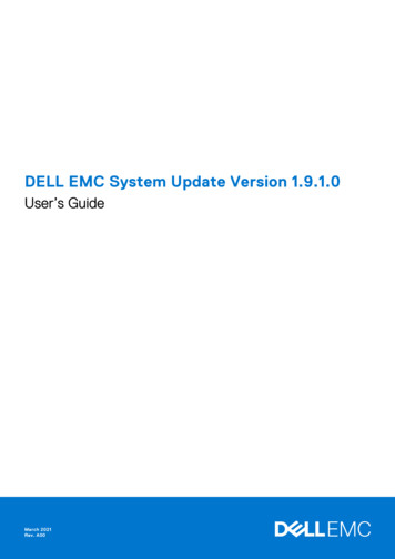
Chapter 1BASIC AC THEORYContents1.11.21.31.41.51.61.71.1What is alternating current (AC)?AC waveforms . . . . . . . . . . . . .Measurements of AC magnitude .Simple AC circuit calculations . .AC phase . . . . . . . . . . . . . . . .Principles of radio . . . . . . . . . .Contributors . . . . . . . . . . . . . .161219202325What is alternating current (AC)?Most students of electricity begin their study with what is known as direct current (DC), whichis electricity flowing in a constant direction, and/or possessing a voltage with constant polarity.DC is the kind of electricity made by a battery (with definite positive and negative terminals),or the kind of charge generated by rubbing certain types of materials against each other.As useful and as easy to understand as DC is, it is not the only “kind” of electricity in use.Certain sources of electricity (most notably, rotary electro-mechanical generators) naturallyproduce voltages alternating in polarity, reversing positive and negative over time. Either asa voltage switching polarity or as a current switching direction back and forth, this “kind” ofelectricity is known as Alternating Current (AC): Figure 1.1Whereas the familiar battery symbol is used as a generic symbol for any DC voltage source,the circle with the wavy line inside is the generic symbol for any AC voltage source.One might wonder why anyone would bother with such a thing as AC. It is true that insome cases AC holds no practical advantage over DC. In applications where electricity is usedto dissipate energy in the form of heat, the polarity or direction of current is irrelevant, solong as there is enough voltage and current to the load to produce the desired heat (powerdissipation). However, with AC it is possible to build electric generators, motors and power1
CHAPTER 1. BASIC AC THEORY2DIRECT CURRENT(DC)ALTERNATING CURRENT(AC)IIIIFigure 1.1: Direct vs alternating currentdistribution systems that are far more efficient than DC, and so we find AC used predominatelyacross the world in high power applications. To explain the details of why this is so, a bit ofbackground knowledge about AC is necessary.If a machine is constructed to rotate a magnetic field around a set of stationary wire coilswith the turning of a shaft, AC voltage will be produced across the wire coils as that shaftis rotated, in accordance with Faraday’s Law of electromagnetic induction. This is the basicoperating principle of an AC generator, also known as an alternator: Figure 1.2Step #1Step #2SNSN -no current!IILoadLoadStep #3Step #4NSNSno current!- ILoadILoadFigure 1.2: Alternator operation
1.1. WHAT IS ALTERNATING CURRENT (AC)?3Notice how the polarity of the voltage across the wire coils reverses as the opposite poles ofthe rotating magnet pass by. Connected to a load, this reversing voltage polarity will create areversing current direction in the circuit. The faster the alternator’s shaft is turned, the fasterthe magnet will spin, resulting in an alternating voltage and current that switches directionsmore often in a given amount of time.While DC generators work on the same general principle of electromagnetic induction, theirconstruction is not as simple as their AC counterparts. With a DC generator, the coil of wireis mounted in the shaft where the magnet is on the AC alternator, and electrical connectionsare made to this spinning coil via stationary carbon “brushes” contacting copper strips on therotating shaft. All this is necessary to switch the coil’s changing output polarity to the externalcircuit so the external circuit sees a constant polarity: Figure 1.3Step #1N SStep #2N SN SN S- - ILoadLoadStep #3N SStep #4N SN SN S- - ILoadLoadFigure 1.3: DC generator operationThe generator shown above will produce two pulses of voltage per revolution of the shaft,both pulses in the same direction (polarity). In order for a DC generator to produce constantvoltage, rather than brief pulses of voltage once every 1/2 revolution, there are multiple setsof coils making intermittent contact with the brushes. The diagram shown above is a bit moresimplified than what you would see in real life.The problems involved with making and breaking electrical contact with a moving coilshould be obvious (sparking and heat), especially if the shaft of the generator is revolvingat high speed. If the atmosphere surrounding the machine contains flammable or explosive
CHAPTER 1. BASIC AC THEORY4vapors, the practical problems of spark-producing brush contacts are even greater. An AC generator (alternator) does not require brushes and commutators to work, and so is immune tothese problems experienced by DC generators.The benefits of AC over DC with regard to generator design is also reflected in electricmotors. While DC motors require the use of brushes to make electrical contact with movingcoils of wire, AC motors do not. In fact, AC and DC motor designs are very similar to theirgenerator counterparts (identical for the sake of this tutorial), the AC motor being dependentupon the reversing magnetic field produced by alternating current through its stationary coilsof wire to rotate the rotating magnet around on its shaft, and the DC motor being dependent onthe brush contacts making and breaking connections to reverse current through the rotatingcoil every 1/2 rotation (180 degrees).So we know that AC generators and AC motors tend to be simpler than DC generatorsand DC motors. This relative simplicity translates into greater reliability and lower cost ofmanufacture. But what else is AC good for? Surely there must be more to it than design detailsof generators and motors! Indeed there is. There is an effect of electromagnetism known asmutual induction, whereby two or more coils of wire placed so that the changing magnetic fieldcreated by one induces a voltage in the other. If we have two mutually inductive coils and weenergize one coil with AC, we will create an AC voltage in the other coil. When used as such,this device is known as a transformer: Figure 1.4TransformerACvoltagesourceInduced ACvoltageFigure 1.4: Transformer “transforms” AC voltage and current.The fundamental significance of a transformer is its ability to step voltage up or down fromthe powered coil to the unpowered coil. The AC voltage induced in the unpowered (“secondary”)coil is equal to the AC voltage across the powered (“primary”) coil multiplied by the ratio ofsecondary coil turns to primary coil turns. If the secondary coil is powering a load, the currentthrough the secondary coil is just the opposite: primary coil current multiplied by the ratioof primary to secondary turns. This relationship has a very close mechanical analogy, usingtorque and speed to represent voltage and current, respectively: Figure 1.5If the winding ratio is reversed so that the primary coil has less turns than the secondarycoil, the transformer “steps up” the voltage from the source level to a higher level at the load:Figure 1.6The transformer’s ability to step AC voltage up or down with ease gives AC an advantageunmatched by DC in the realm of power distribution in figure 1.7. When transmitting electricalpower over long distances, it is far more efficient to do so with stepped-up voltages and steppeddown currents (smaller-diameter wire with less resistive power losses), then step the voltageback down and the current back up for industry, business, or consumer use.Transformer technology has made long-range electric power distribution practical. Without
1.1. WHAT IS ALTERNATING CURRENT (AC)?5Speed multiplication geartrain"Step-down" transformerLarge gear(many teeth)Small gear(few teeth) high voltageACvoltagesourcelow voltagemanyturnslow torquehigh speedhigh torquelow speedfew turnsLoadhigh currentlow currentFigure 1.5: Speed multiplication gear train steps torque down and speed up. Step-down transformer steps voltage down and current up."Step-up" transformerSpeed reduction geartrainLarge gear(many teeth)high voltageSmall gear(few teeth)low voltage low torquehigh speedACvoltagesourcemany turnsfew turnsLoadhigh currenthigh torquelow speedlow currentFigure 1.6: Speed reduction gear train steps torque up and speed down. Step-up transformersteps voltage up and current down.high voltagePower PlantStep-up. . . to other customerslow voltageStep-downHome orBusinesslow voltageFigure 1.7: Transformers enable efficient long distance high voltage transmission of electricenergy.
CHAPTER 1. BASIC AC THEORY6the ability to efficiently step voltage up and down, it would be cost-prohibitive to constructpower systems for anything but close-range (within a few miles at most) use.As useful as transformers are, they only work with AC, not DC. Because the phenomenon ofmutual inductance relies on changing magnetic fields, and direct current (DC) can only producesteady magnetic fields, transformers simply will not work with direct current. Of course, directcurrent may be interrupted (pulsed) through the primary winding of a transformer to createa changing magnetic field (as is done in automotive ignition systems to produce high-voltagespark plug power from a low-voltage DC battery), but pulsed DC is not that different fromAC. Perhaps more than any other reason, this is why AC finds such widespread application inpower systems. REVIEW: DC stands for “Direct Current,” meaning voltage or current that maintains constant polarity or direction, respectively, over time. AC stands for “Alternating Current,” meaning voltage or current that changes polarity ordirection, respectively, over time. AC electromechanical generators, known as alternators, are of simpler construction thanDC electromechanical generators. AC and DC motor design follows respective generator design principles very closely. A transformer is a pair of mutually-inductive coils used to convey AC power from one coilto the other. Often, the number of turns in each coil is set to create a voltage increase ordecrease from the powered (primary) coil to the unpowered (secondary) coil. Secondary voltage Primary voltage (secondary turns / primary turns) Secondary current Primary current (primary turns / secondary turns)1.2AC waveformsWhen an alternator produces AC voltage, the voltage switches polarity over time, but doesso in a very particular manner. When graphed over time, the “wave” traced by this voltageof alternating polarity from an alternator takes on a distinct shape, known as a sine wave:Figure 1.8In the voltage plot from an electromechanical alternator, the change from one polarity tothe other is a smooth one, the voltage level changing most rapidly at the zero (“crossover”)point and most slowly at its peak. If we were to graph the trigonometric function of “sine” overa horizontal range of 0 to 360 degrees, we would find the exact same pattern as in Table 1.1.The reason why an electromechanical alternator outputs sine-wave AC is due to the physicsof its operation. The voltage produced by the stationary coils by the motion of the rotatingmagnet is proportional to the rate at which the magnetic flux is changing perpendicular to thecoils (Faraday’s Law of Electromagnetic Induction). That rate is greatest when the magnetpoles are closest to the coils, and least when the magnet poles are furthest away from the coils.
1.2. AC WAVEFORMS7(the sine wave) TimeFigure 1.8: Graph of AC voltage over time (the sine wave).Angle (o )0153045607590105120135150165180Table 1.1: Trigonometric “sine” function.sin(angle) wave Angle (o ) sin(angle)0.0000zero1800.00000.2588 195-0.25880.5000 210-0.50000.7071 225-0.70710.8660 240-0.86600.9659 255-0.96591.0000 peak270-1.00000.9659 285-0.96590.8660 300-0.86600.7071 315-0.70710.5000 330-0.50000.2588 345-0.25880.0000zero3600.0000wavezero-peakzero
CHAPTER 1. BASIC AC THEORY8Mathematically, the rate of magnetic flux change due to a rotating magnet follows that of asine function, so the voltage produced by the coils follows that same function.If we were to follow the changing voltage produced by a coil in an alternator from anypoint on the sine wave graph to that point when the wave shape begins to repeat itself, wewould have marked exactly one cycle of that wave. This is most easily shown by spanning thedistance between identical peaks, but may be measured between any corresponding points onthe graph. The degree marks on the horizontal axis of the graph represent the domain of thetrigonometric sine function, and also the angular position of our simple two-pole alternatorshaft as it rotates: Figure 1.9one wave cycle09018027036090180(0)one wave cycle270360(0)Alternator shaftposition (degrees)Figure 1.9: Alternator voltage as function of shaft position (time).Since the horizontal axis of this graph can mark the passage of time as well as shaft positionin degrees, the dimension marked for one cycle is often measured in a unit of time, most oftenseconds or fractions of a second. When expressed as a measurement, this is often called theperiod of a wave. The period of a wave in degrees is always 360, but the amount of time oneperiod occupies depends on the rate voltage oscillates back and forth.A more popular measure for describing the alternating rate of an AC voltage or currentwave than period is the rate of that back-and-forth oscillation. This is called frequency. Themodern unit for frequency is the Hertz (abbreviated Hz), which represents the number of wavecycles completed during one second of time. In the United States of America, the standardpower-line frequency is 60 Hz, meaning that the AC voltage oscillates at a rate of 60 completeback-and-forth cycles every second. In Europe, where the power system frequency is 50 Hz,the AC voltage only completes 50 cycles every second. A radio station transmitter broadcastingat a frequency of 100 MHz generates an AC voltage oscillating at a rate of 100 million cyclesevery second.Prior to the canonization of the Hertz unit, frequency was simply expressed as “cycles persecond.” Older meters and electronic equipment often bore frequency units of “CPS” (CyclesPer Second) instead of Hz. Many people believe the change from self-explanatory units likeCPS to Hertz constitutes a step backward in clarity. A similar change occurred when the unitof “Celsius” replaced that of “Centigrade” for metric temperature measurement. The nameCentigrade was based on a 100-count (“Centi-”) scale (“-grade”) representing the melting andboiling points of H2 O, respectively. The name Celsius, on the other hand, gives no hint as tothe unit’s origin or meaning.
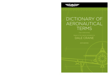
1.2. AC WAVEFORMS9Period and frequency are mathematical reciprocals of one another. That is to say, if a wavehas a period of 10 seconds, its frequency will be 0.1 Hz, or 1/10 of a cycle per second:Frequency in Hertz 1Period in secondsAn instrument called an oscilloscope, Figure 1.10, is used to display a changing voltage overtime on a graphical screen. You may be familiar with the appearance of an ECG or EKG (electrocardiograph) machine, used by physicians to graph the oscillations of a patient’s heart overtime. The ECG is a special-purpose oscilloscope expressly designed for medical use. Generalpurpose oscilloscopes have the ability to display voltage from virtually any voltage source,plotted as a graph with time as the independent variable. The relationship between periodand frequency is very useful to know when displaying an AC voltage or current waveform onan oscilloscope screen. By measuring the period of the wave on the horizontal axis of the oscilloscope screen and reciprocating that time value (in seconds), you can determine the frequencyin Hertz.OSCILLOSCOPEverticalYDC GND ACV/divtrigger16 divisions@ 1ms/div a period of 16 mstimebase1mXs/divFrequency DC GND AC11 62.5 Hzperiod16 msFigure 1.10: Time period of sinewave is shown on oscilloscope.Voltage and current are by no means the only physical variables subject to variation overtime. Much more common to our everyday experience is sound, which is nothing more than thealternating compression and decompression (pressure waves) of air molecules, interpreted byour ears as a physical sensation. Because alternating current is a wave phenomenon, it sharesmany of the properties of other wave phenomena, like sound. For this reason, sound (especiallystructured music) provides an excellent analogy for relating AC concepts.In musical terms, frequency is equivalent to pitch. Low-pitch notes such as those producedby a tuba or bassoon consist of air molecule vibrations that are relatively slow (low frequency).
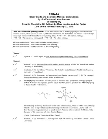
CHAPTER 1. BASIC AC THEORY10High-pitch notes such as those produced by a flute or whistle consist of the same type of vibrations in the air, only vibrating at a much faster rate (higher frequency). Figure 1.11 is a tableshowing the actual frequencies for a range of common musical notes.NoteMusical designationAA sharp (or B # or Gb369.99G392.00GAA sharp (or B flat)BCbD or EFG sharp (or A flat)246.94CEF sharp (or G flat)233.08C# or DbDD sharp (or E flat)220.00bA or BB1C (middle)C sharp (or D flat)Frequency (in hertz)#bG or A415.30A440.00A# or Bb466.16B493.88C1523.25Figure 1.11: The frequency in Hertz (Hz) is shown for various musical notes.Astute observers will notice that all notes on the table bearing the same letter designationare related by a frequency ratio of 2:1. For example, the first frequency shown (designated withthe letter “A”) is 220 Hz. The next highest “A” note has a frequency of 440 Hz – exactly twice asmany sound wave cycles per second. The same 2:1 ratio holds true for the first A sharp (233.08Hz) and the next A sharp (466.16 Hz), and for all note pairs found in the table.Audibly, two notes whose frequencies are exactly double each other sound remarkably similar. This similarity in sound is musically recognized, the shortest span on a musical scaleseparating such note pairs being called an octave. Following this rule, the next highest “A”note (one octave above 440 Hz) will be 880 Hz, the next lowest “A” (one octave below 220 Hz)will be 110 Hz. A view of a piano keyboard helps to put this scale into perspective: Figure 1.12As you can see, one octave is equal to seven white keys’ worth of distance on a piano keyboard. The familiar musical mnemonic (doe-ray-mee-fah-so-lah-tee) – yes, the same patternimmortalized in the whimsical Rodgers and Hammerstein song sung in The Sound of Music –covers one octave from C to C.While electromechanical alternators and many other physical phenomena naturally produce sine waves, this is not the only kind of alternating wave in existence. Other “waveforms”of AC are commonly produced within electronic circuitry. Here are but a few sample waveformsand their common designations in figure 1.13
1.2. AC WAVEFORMSC# D#Db Eb11F # G # A#G b Ab BbC# D#Db EbF # G # A#G b Ab BbC# D#Db EbF # G # A#G b Ab BbC D E F G A B C D E F G A B C D E F G A Bone octaveFigure 1.12: An octave is shown on a musical keyboard.Square waveTriangle waveone wave cycleone wave cycleSawtooth waveFigure 1.13: Some common waveshapes (waveforms).
CHAPTER 1. BASIC AC THEORY12These waveforms are by no means the only kinds of waveforms in existence. They’re simplya few that are common enough to have been given distinct names. Even in circuits that aresupposed to manifest “pure” sine, square, triangle, or sawtooth voltage/current waveforms, thereal-life result is often a distorted version of the intended waveshape. Some waveforms areso complex that they defy classification as a particular “type” (including waveforms associatedwith many kinds of musical instruments). Generally speaking, any waveshape bearing closeres
Sixth Edition, last update July 25, 2007. i c 2000-2020, Tony R. Kuphaldt This book is published under the terms and conditions of the Design Science License. These . electricity is known as Alternating Current (AC): Figure 1.1 Whereas the familiar battery symb