Transcription
Vacupress Apparatebauund technisches ZubehörPeter WitzelMax Keith Str. 66 - 45136 EssenTel. 0201 / 6462-284 - Fax: 0201 / 6462-852info@vacupress.de/ www.vacupress.deVACUPRESS620 S3 - UNILOCKMANUALOperations and maintenanceBefore the first commissioning of the unitplease read the safety instructions on page 10!This manual is an integral part of the installation and must behanded over to a new owner in case of sale or to an operator incase of use by a third party.Version 2008/06 (C) (220-115/60/1 USA)
IndexChapterIndexPage11.11.21.31.41.5SummaryShort description of the unitTechnical specificationPurpose of the VACUPRESS unitManualDefinitions55678822.12.22.2.1Safety InstructionsReading of the manualConnectionsCheck of power supply101010102.32.3.12.3.22.3.32.3.42.3.5Advice of hazards during operationWorking frameRadiation heatingFoilsWorking 3.83.93.10Description of FunctionMain switchMain handleThe UNI LOCK systemRadiation heatingIlluminationTimer for the radiation heatingActivation grillVentCOOL-TEC Cooling-SystemAir filter14141414141515161616172
ChapterIndexPage44.14.24.34.44.54.6Operation instructionsFixing of the working membraneInsert the material to be formedMoulding of foils without working membraneCooling of thermoplastics with COOL-TECRemoval of the moulded materials foilsTimes of eVacuum pumpHeatingGuiding of the working frameBall jointsUNI LOCKAir filter – and .1.56.1.66.1.7RepairSpare part listFrontRight sideLeft sideRadiatorInteriorBacksideWorking 56.2.66.2.7Location of partsFrontRight sideLeft sideRadiatorInteriorBacksideWorking frame28282829293031323
ChapterIndexPage7Vacuum pump – spare part list338Circuit diagram349Outline of control elements3510Adjustment of pressure switch36Declaration of Conformity37Removal of the moulded foils214.54
1Summary1.1Short description of the unitVACUPRESS Type 620 S3 automatic with the UNI LOCK system has beendeveloped as a powerful tool to form plastic foils over complicated models.This forming technique called deep drawing or moulding is used mainly in theorthopaedic manufacturing to copy human limbs. For the deep drawing processVACUPRESS uses a bench on which the model is fixed. The foil is laid over themodel and on the foil a high flexible working membrane is pressed. The workingmembrane is stretched in a frame which will be lowered around the model down tothe bench. A vacuum pump is used to evacuate the air beneath the membrane. Theatmospheric pressure presses the membrane onto the foil with high force. The foilwill be formed truly according to the model. Alternatively the foil itself can be usedinstead of the working membrane.An integrated radiation heating device is used to heat up the material.The vacuum pump can also be used for suction purposes during working in the resincasting technique.5
1.2Technical specificationTyp:VACUPRESS 620 S3 automaticDeep drawing unit for theorthopaedic shoe technique, table unitManufacturer:VACUPRESS Peter Witzel – D-45136 EssenPhone 49/201/6462284 / Fax 49/201/6462852Series-no.:See name plateWorking area:Width:Depth:Frame size:Vacuum shaft:approx. 0,34m²730 mm (incl. main handle)600 mm600 x 450 mmWidth 110 mmLength 195 mmDepth 140 mm147 kgVacuum pump / oil-free1 external vacuum-outlet / connection for vacuum distributor1 external compr.-air-inlet / for COOL-TEC System supply220-115V / 60 Hz / 1 Phase (4 wire, 2 hot Neutral Ground)5,9 kWWeight:Driving force:Connections:Electric power:Rating:6
1.3Purpose of the VACUPRESS unitThe use of the VACUPRESS is restricted to the following purposes:.1.2.3.4.5.6.7Moulding works with pre-heated plastics under the working membrane.Pressing of other materials, e.g. leather or cork, cold or pre-heated under theworking membrane.Moulding of PVC or other foils on models of plaster, wood or hard foam whichare thermo plastic.Moulding of foils up to 2 mm thickness, heated up in the unit.Moulding with sheets more than 2 mm thickness pre-heated outside the unit,e.g. in an oven.Use of the vacuum pump for suction purposes during working in the resincasting technique.Use of the radiation heating for activation of material up to 50 seconds.All other applications are not allowed.7
1.4ManualThis manual· describes the elements of the unit· explains the procedures of the process· gives the craft reliable instructions for the use of the unit· draws the attention to the working risks· and gives hints for maintenance and repair1.5DefinitionSee drawings and pictures on the last pages.Activation grillAdjustable grill underneath the radiator for heating (activating)glues and foils.Air filterAir filter upstream the vacuum pump.UNI LOCK boltsBolts on the side of the tentering frame to which the hooks of theUNI LOCK system are engaged.Working frameFrame (d) into which the working membrane is fixed.Tentering frameFrame that fixes the working membrane in the working frame.UNI LOCKPatented system to lock two frames together to fix a membranein between.Venting tapTap inside the unit with an outside handle (f) to control the inletof air to the working membrane and to release the membrane atthe end of the working process.UNI LOCK handle Handle (c) to control the UNI LOCK.Main handleHandle (b) on the right side of the VACUPRESS bench.Moves the working frame and the fixing frame.8
Working plateUpper surface of the VACUPRESS bench.On this plate the model is fixed.Beneath the plate there are· electrical controls· vacuum pump· venting tapMain switchSwitch (a) to switch the electrical supply for vacuum pump,radiation heating and electrical controls.Limit switchLimit switch (e), initiated if the main handle reaches the upperposition. When initiated the vacuum pump starts.Pressure switchPressure switch (S3) controls the suction pressure on thesuction side of the vacuum pump. Below –0.8 bar the motorstops, above –0.4 bar the motor is switched on.TimerThe timer (k) switches the radiation heating on and stops it at theend of the programmed time.Radiation heating Radiator (h) for heating foils, clamped directly into the workingframe or materials put onto the activation grill.COOL-TECintegrated cooling system for thermoplastic materials which havebeen molded with the VACUPRESS unit. Works withcompressed air (external supply) which is reduced by anintegrated pressure reducer to 1.5 bar (21,7 psi).Star gripThe screw with star grip (i) is used to adjust the position of theactivation grill and to remove or shift the grill.Working membrane High flexible membrane which directs the atmosphericpressure to all sides of the model. Preferable consisting ofrubber. Heated foils can be used instead.9
2Safety InstructionsThese safety instructions have to be followed before each installation andcommissioning.2.1Reading of this manualPlease read this manual before connecting the VACUPRESS unit to an electricalsource or before commissioning!This manual describes e.g. risks which exist in connection with improper use.Take care that each operator of the unit is familiar with this manual.Pay attention that this manual will always be available close to the unit.This manual is an integral part of the installation. It must be handed over to anew owner or operator in case of sale etc.2.2Connections2.2.1 Check of power supplyThe correct wiring of the power supply has to be checked by a licensed electrician.You need a power source of 220/115 Volt / 60 Hz / 1 Phase (2 hot/N/PE). Anincorrect wiring of the Neutral (N) will cause an immediate damage of the timer.A correct wiring is not guaranteed even if other installations have been runningcorrectly on the same electrical source.10
2.3Possible hazards during operation2.3.1 Working frameRisk of contusion exists for extremities during lifting and lowering of the workingframe as well during opening and closing of the fixing frame.Attention – Danger of contusion !11
2.3.2 Radiation heatingDanger of burns exists in the area of the protecting grill of the radiators.During operation of the radiator the surrounding parts of the unit will reach hightemperature incl. the protecting grill. Please do not reach the area of the radiatorwith your hands.The radiator is made for the handicraft production of single parts of plastic. If morethan two parts have to be heated up a sufficient cooling of the working frame andother hot parts of the unit have to be achieved.Attention – Always wear protecting gloves !2.3.3 FoilsDo not exceed the specified heating times (see point 4.5). Inflammable andpoisoning gases may be produced unintentionally.Supervise the heating process.Supervise the heating process with other materials as well.Attention – Danger of fire !12
2.3.4Working membraneBursting of the working membrane may lead to a hearing defect.Danger of burst exists using the working membrane for tall models. This goes with aloud bang.It is recommended to wear ear protection.This is also recommended for other persons working close to the installation.Attention – High noise level possible !Wear ear protection !2.3.5 SolventsDanger of explosion exists using solvents. Do not use solvents (for exampleacetone, spirit, gasoline, paint dilution etc.) during moulding. Solvents can produceexplosive mixtures within the unit.Attention – Danger of explosion !13
3Description of Function3.1Main switch (a)With the main switch power supply is controlled for the vacuum pump, radiationheating and the control circuit. Put the switch into the position ON. Now theinstallation is on stand-by. This switch can be ON during the whole day. During alonger absence the switch should be put into the OFF position (uncontrolledelectrical unit).3.2Main handle (b)The main handle has 3 tasks:· The main handle is used to lift and lower the working frame.In the upper position the handle locks the frame vacuum tight to the workingplate.· It opens and closes the tentering frame on the working frame to insert a workingmembrane or a foil. It supports the UNI LOCK mechanism in pressing thetentering frame to the working frame.· In the upper position it actuates the limit switch (e) to start the vacuum pump.3.3The UNI LOCK systemThe UNI LOCK system locks with only one movement the tentering frame to theworking frame, with the working membrane in between.Via a connecting rod the UNI LOCK handle (c) moves two hooks, the UNI LOCKhooks. They are attached to the working frame. The hooks grip onto two bolts at thetentering frame. Because of the movement of the UNI LOCK handle the tenteringframe is pulled against the working frame clamping the working membrane.The design of the tentering frame allows the use of material with different thickness,e.g. plates or foils, without a correction of the clamping power.3.4The workplace illumination (x)The illumination of the workplace can be turned on by the small green switch on theright hand of the front panel (main switch has to be turned ON). When theillumination is turned on, the switch is additionally illuminated. When the machineturned OFF by the main switch, the workplace illumination will be turned off as well.14
3.5Radiation heating (h)The infrared-Quartz-radiator (h) is a very quick heating with a rating of 5.4 kW. Theheating process lasts up to 150 seconds. The heating should always be supervisedcarefully.The radiator produces plasticity of plastic foils up to 3 mm thickness.Heating of thicker plates, for example Polyethylene, is not possible and isdangerous. Thicker material should be treated in a hot air closet.Activation of glue and plasticity of stiffing material is possible and has to be carefullysupervised. For this materials it is wise to use less aggressive heating means, likeinfrared lamps of hot air heating.3.6Timer for the radiation heating (z)For safety reasons the radiation heating is controlled only with the timer (z).The heating sequence in seconds can be adjusted manually between 30 and 200seconds with the “ ” or “-“ keys (k). The programmed time is shown on the right LEDdisplay. With the “START” key the radiator is switched on. The timer now displaysthe running time on the left LED display. At “000” an alarm sounds and the radiator isswitched off. Now the timer displays the programmed time and is ready to startagain. By pushing the “STOP” key the heating process can be interrupted at anytime.Advice: Rather try with a lower heating time and repeat if necessary. Keep theheating process under control. During heating never leave the unit. If necessaryinterrupt the heating process with the “STOP” and start again later on.3.7Activation unit (n)The activation grill can be adjusted into different positions.The distance to the radiator can be adjusted by the star grip (i). The fixture with thestar grip is movable to the side. It can be positioned to the left or right side of theradiation heating. To avoid risk of collision do not position the grill to the side wherepeople are working. If the grill is not used it can be turned upside down to the top ofthe machine. To do so pull the snap-in bolt and slue the grill 180 to the top.15
To avoid an accidental sluing, always take care that the snap-in bolt has restedcorrectly again after the sluing process (up- or downwards) and the grill islocked!The materials are placed on the grill to be activated. The heating process iscontrolled by the distance to the radiator and the duration of heating.Use rather short heating intervals and turn over the material after each heating.3.8COOL-TEC cooling systemThe VACUPRESS 620 S3 UNILOCK is equipped with the full integrated coolingsystem COOL-TEC. This special system allows to cool down the moldedthermoplastics much faster and thus to demold them faster as well.The COOL-TEC system is working with compressed air which is supplied by anexternal inlet (t) with the compressed air line of your workshop. The pressure isinternally reduced to 1.5 bar (21,7 psi) by a pressure reducer (u). This step incombination with others allows to reduce the consumption of compressed air to aminimum.The cooling effect is reached by the use of two air-saving special nozzles (v1) whichare placed on both sides behind the heat radiator facing. By use of an adjustmentknob (v2) at the front side of the heat radiator facing, the air jets can be alignedindividually to the models molded in the VACUPRESS unit. Turning ON and OFF theCOOL-TEC system takes place by a small pneumatics switch (w) at the unit’s frontpanel.3.9Venting tap (f)The venting tap (f) has two tasks:···During a moulding process it allows to inject air to slow down the suction of airfrom the model. Open the vent partly (lever to the left side) to inject air.At the end of the moulding process air is led under the model to release theworking membrane. The air enters with the vent handle in the position “OPEN”.Be aware that the vent (f) has been closed before the start of the mouldingprocess. Position “CLOSED”, lever upwards.16
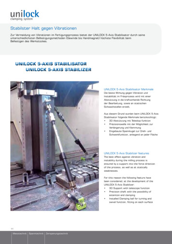
3.10Air filterThe vacuum pump evacuates the air between working membrane and working plate.An air filter on the suction side avoids the entering of dust particles into the vacuumpump. Decreasing suction efficiency indicates clogging of the air filter (see point 5.6Maintenance).A second filter in integrated in the hose of the extern Vacuum-connection. This onecleans the air which is externally suctioned.sDrawing topoint 4.1c17b
4.Operation instructionsThese instructions describe the operation procedure in a step by step manner.Legend:·A figure (i.e. .1) is used to instruct an action (e.g. step 4.1.1)·A star is used to instruct a check. The indicated condition must bepresent before the start of the next action·A hyphen – is used to indicate a consequence or a result of the ordered step.4.1Fixing of the working membrane*No model on the working table.1.2.3.4.5.6Turn main switch to OFF positionMove main handle (b) into the upper position- The working frame is lowered to the tablePull UNI LOCK handle (c)- The UNI LOCK hooks are releasedPush main handle (b) into the upper position and hold- The UNI LOCK hooks (s) are released from the bolts on the tenteringframe.By holding the main handle (b) turn down UNI LOCK handle (c) and holdit. - This will move the hooks (s) from the bolts.Move main handle (b) to the lower position.- This opens up the tentering frame. Release UNI LOCK (c) handle.*If an used membrane was fixed in the working frame, remove it.18
.7.8Put the working membrane into the working frame and adjust it.Move main handle (b) into the upper position.- The tentering frame will be closed. The membrane will be fixed. TheUNI LOCK hooks (s) click to the bolts. Let go the main handle.*Both UNI LOCK hooks (s) are engaged.9Push down the UNI LOCK handle (c).- The tentering frame is locked to the working frame.Attention – Danger of contusion4.2Insert the material to be formed*The working frame is in the upper position.*A working membrane is fixed in the working frame.1.2.3.4.5Turn main switch (a) to ONMove handle of venting tap (f) into position CLOSED.Place model on the working table. Be aware of central position.Place the material to be formed on to the model and fix it, if necessary.Move main handle into the upper position.- The working membrane is lowered, the working frame contacts thetable. The vacuum pump starts, the vacuum is controlled automatically.Advice:To achieve a plaster-cast which surrounds the model completely the model has tobe positioned on a small support. So the foil can follow the contours even to theunderside of the model19
4.3Moulding of foils without working membrane.1.2.3.4Remove working membrane, see point 4.1.1 – 4.1.5Insert the foil to be moulded into the working frame, see point 4.1.6 – 4.1.8Move main handle into the lower position.- Working frame moves into the upper position.Adjust the required heating time on the timer to warm up the foil.Be aware of hazards, see point 2.3.3 Check plasticity of foil after heating process, restart heating if necessary.5Move main handle upwards with care- The working frame is lowered, the foil is put onto the model. In theupper position of the main handle the vacuum pump starts. Now the foilsurrounds the model completely.If necessary move handle of venting tap (f) slightly in the direction to positionOPEN.- The process of moulding in its critical phase (right before reaching thefinal form ) may be improved by slowing down the process. Addition ofair is used to slow down the procedure.620
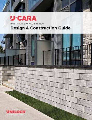
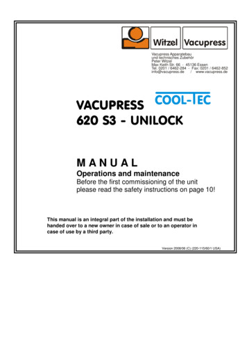
4.4Cooling of molded thermoplastics by use of the COOL-TEC system.1.2.3.4First ensure that the external compressed air inlet (t) is connected to yourworkshop’s compressed air line and a pressure of minimum 1.5 bar (21,7 psi)is supplied.Activate the COOL-TEC cooling-system by turning ON the „cooling“ switch (w)at the unit’s front panel.Align the air nozzles (v1) by use of the adjustment knobs (v2) in the way thatthe air is „flowing“ around your model(s) in the optimal way.After the thermoplastic material is cooled down as far as it can be demolded(depends on kind and thickness of material) you can turn OFF the COOL-TECcooling-system again by use of the “Cooling” switch (w) at the unit’s frontpanel.Overview COOL-TEC elementsswitch „Cooling„ON - OFF(w)External compressed airinlet (t)Adjustment knob for leftair nozzle (v2)Left special air nozzle(v1)21
4.5Removal of the moulded foils4.5.1 Foils moulded with working membrane.1.2.3.4Pull main handle (b) from the upper position.- The vacuum pump is switched off.Move handle of venting tap (f) to position OPEN.- Air flows into the area of the moulded foil. The form is released from themodel. The working membrane is released from the foil and the table.Move main handle to the lower position.- The working frame is elevated to the upper position.The moulded form can be removed.4.5.2 For the removal of foils, which have been fixed to the working frame.1.2.3.4.5.6Pull up UNI LOCK handle (c)- The UNI LOCK hooks (s) are loosened.Push main handle (b) into the upper position- By pressing the tentering frame against the working frame the hooks(s) are freed from the bolts on the tentering framePush down and hold UNI LOCK handle (c)- The hooks (s) are released.Move main handle (b) into the lower position- The tentering frame is opened up and releases the moulded foil.The moulded foil is released from the model.The moulded form can be removed.22
4.6Times of heatingThe following times are recommended. Specific times will be ensued fromexperience.Material:PVC clear foils 0.4 mmPVC clear foils 1.2 mmBathing slipper-material 6 mmHeating time approx.45 sec.75 sec.200 sec. In intervals of 40 sec. eachWith interruption of 15 sec. to heat thematerial thoroughlyDanger: Never use heating times longer than 200 sec. Rather repeatthe heating process.Supervise the heating process carefully to avoid danger of fire.Attention – Danger of fire !23
5Maintenance5.1Vacuum pumpVACUPRESS 620 S3 - automatic is supplied with an oil free, e.g. maintenancefree vacuum pump.ATTENTION!If you are often using wet materials or models, it is necessary to let the pumprun for a few minutes after you have finished your work! Otherwise humiditymay reach the pump and in the case of longer standstill (e.g. at the weekend)the pump may stuck and can be damaged!5.2HeatingClean regularly the resistors of the radiator and the grill. Use compressed air ora vacuum cleaner and a soft brush.5.3Guidance of the working frameThe 16 ball bearings of the frame guidance are maintenance free. Oil the pivot ofthe main handle from time to time.5.4Ball jointMaintenance free.5.5UNI LOCKOil the pivot of the UNI LOCK hooks. An adjustment of the tentering frame andits UNI LOCK bolts is necessary after 3 years of operation. The anti slip coating onthe yellow frame has to be renewed all 3 years.Attention: Never adjust the self locking nuts on the tentering frame.The tentering function can be disturbed significantly.24
5.6Air filterThe filter is mounted inside the bench. To exchange the filter cartridge loosen thetwo star grip screws M 6 on the back of the unit and remove the cover on the backside.5.6.1 Replacement of the air filterRemove the filter cartridge by an anti-clockwise turn. Oil the rubber seal beforemounting. Do not use any mechanical means – tighten the cartridge only manually.5.6.2 Replacement of the air filter (extern connection)This Filter you can reach also from the backside. Right underneath the (main) filteryou find it (in the vacuum-hose integrated brass unit). To clean it, open the uppersealing plug. Inside you find a small wire netting filter which can be cleaned by usingcompressed air.25
6RepairAll parts of VACUPRESS 620 II Automatic are long life and reliable industrialarticles. They are liable to a thorough quality assurance in the manufacturingprocess of VACUPRESS. Therefore, a regular repair is not scheduled.In case of ordering spare parts the following list gives a clear definition of each part.The list is arranged according to the location of the resp. parts. See sketches.6.1Spar part listNo.DesignationType6.1.1 um meterMain switchThree-way ball valveHeating selection switch (optional)Switch for workplace illumination (green)Type VASU 19963 mmKH20-T204½”7009867003046.1.2 Right side620115620391620329620330620331Limit switchLink rodBall jointMotor protection (therm.)external plug connector (not for export)AT 11 1 iM10 260x30x30KBRM-10 MH2AERSO-BL6.1.3 Left side620391620196620329Link rodStop screwBall jointM10 260x30x30M 8 x 40KBRM-10 MH6.1.4 ing resistor 1pc.conduit box with clampslamp holder for 12V Halogen SpotlightHalogen Spotlight 12V / 20WAKOAKOHP80EBL-3860HL20W26
6.1.5 620389620390Vacuum pumpVacuum hosePressure switchCheck valveHeating relayHeating cut outTransfomer 12V / 60VA (illumination)Air FilterAir filter for ext. conn.6.1.6 Rear er guidance compl.Roller railsCross tieMini bearingSleeveGas suspensionTension spring100 / 890 mmKVR 2 D 25/30 x 30EFOM-1515 x 17B1B1-03-450-105-230NLi 30x25.00x68.1Frame sealingTentering frame sealingAnti-slip coatingThrust spring20 x 20 mm, 620 x 45020 x 5 mm, 620 x 450620 x 450280 x 11.20 xTension spring(tentering frame)Tension spring (UNI LOCK)SleeveTorsion springBronze bushingHandle UNI LOCK17/1/212/3/112 x 125632BP25 14 x 20 x 22 mmGn 310-10-125-D6.1.7 Working 5620409620346620331272750 BGHI / 115V13 mm insideXMLB02V1S12½” 227.32DILEM10PKZM0-10570872MPS-050-0-P10-A60/1K
6.2620152Location of parts6.2.1 Front620170620151w6201536201196201516.2.2 Right Side62039162032962033162033062011528
6.2.3 Left Side620329620391t6.2.4 Radiator 9
6.2.5 620042620114620080Front30
6.2.6 31
6.2.7 Working 7620099620409(hidden)62033132620345620346
7Vacuum pump – spare part list33
8. . Circuit diagram (220/115 volt / 60 Hz)S1 main switchS2 limit switchS3 pressure switch (vaw)(4 wire, 2x hot, 1x neutral, 1x ground)F1 motor protection switch (pump)F2 fuse 32A (heating)M motor vacuum-pumpK1 relay (heating)K2 timerblack wirebrown wirewhite (light grey) wiregreen/yellow wire(ground / Protection earth)34
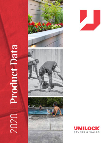
9. Outline of control elementsv1 v2ihnxdscbzwekfya35
10. Adjustment of the pressure switchThe pressure switch is easy to reach from outside on the left side of the housing. Theadjustment of the set-screw for the upper shut-off point of the vacuum-pump is locatedbehind the labeled opening at the housing. The upper shut-off point can be adjusted by useof a fitting screw-driver.The standard shut-off point is set to approx. –0,8 bar.To REDUCE ( - ) the shut-off point, turn the set-screw to the RIGHT.To INCREASE ( ) the sut-off point, turn the set-screw to the LEFT.ATTENTION! Always adjust the set-screw just for approx. a ½ turn and than first check theresult of your adjustment. A massive disadjustment of the pressure switch can cause amalfunction and thus the vacuum-pump might not turn on or off at all.Please don t hesitate to contact our technical support in case of any check-backs orproblems. Phone number: 49 201 6462284.36
Declaration of Conformityfor theDeep Drawing Unit VACUPRESS 620 S3 COOL-TECPeter Witzel Witzel VACUPRESS ApparatebauMax Keith Str. 66D – 45136 Essendeclares as manufacturer and in sole responsibility that the deep drawing unitVACUPRESS 620 S3 complies with the requirements of the directive 89/392 EU andthe German regulation for the safety of appliances "Gerätesicherheitsgesetz".For further information Peter Witzel Witzel Apparatebau provides the technicaldocumentation:Documents of development and design, description of steps for the declaration ofconfirmity, analysis of hazards, analysis of the instruction duties and an operationmanual, which complies with the rules for the production of the user information.The Declaration of Conformity for the the deep drawing unit VACUPRESS 620 S3 isguaranteed.Essen, den 01.03.2006Peter WitzelVACUPRESS Apparatebau37
VACUPRESSGIVES YOU MORE . and each day you’ll findnew ways to manufactureyour products moreefficiently38
620 S3 - UNILOCK M A N U A L Operations and maintenance Before the first commissioning of the unit . 9 Outline of control elements 35 10 Adjustment of pressure switch 36 Declaration of Conformity 37 4.5 Removal of the