Transcription
King Fahd University of Petroleum & MineralsDepartment of Electrical EngineeringEE201Electric CircuitsLaboratory ManualAugust 2003Prepared byDr. A. H. Abdur-RahimNoman Tasadduq
PrefaceThe EE 201 : Electric Circuits Lab is designed to help students understand thebasic principles of electric circuits as well as giving them the insight on design,simulation and hardware implementation of circuits. The main aim is to providehands-on experience to the students so that they are able to put theoreticalconcepts to practice.Each experiment consists of two parts, ‘simulation’ and ‘hardwired’. Computersimulation is stressed upon as it is a key analysis tool of engineering design.“Multisim Electronics Workbench” software is used for simulation of electriccircuits.Students will also carry out a design experiment in addition to the tenexperiments provided in this lab manual. Students will be given a specificdesign problem, which after completion they will verify using the simulationsoftware.
List of ExperimentsExp No.Title1Electrical Circuits Simulation using Multisim ElectronicsWorkbench: An Introduction2Electric Circuit Fundamentals103Resistors in Series, Color Codes & Power Rating154Kirchhoff’s Laws215Series & Parallel Circuits, Voltage Divider & CurrentDivider Rules246Superposition Theorem297Thevenin’s Theorem and Maximum Power Transfer338Transients of a First Order RC Circuit379The Oscilloscope and Function Generator4110Sinusoidal AC Analysis48Appendix Laboratory Regulations and Safety RulesPage153
Experiment 1Electrical Circuits Simulation usingMultisim Electronics Workbench: An IntroductionSimulation is a mathematical way of emulating the behavior of a circuit. With simulation,you can determine a circuit’s performance without physically constructing the circuit or usingactual test instruments. Multisim is a complete system design tool that offers a very largecomponent database, schematic entry, full analog/digital SPICE simulation, etc. It also offersa single easy to use graphical interface for all design needs.IntroductionGo to StartàProgramsàMultisim and click on Multisim. This will open the main windowas shown in Figure 1. In Figure 1 important toolbars and menu are labeled. In addition totoolbars shown in Figure 1, there maybe other toolbars appearing on your screen concentrateon the labeled items in Figure 1 at this time.You can always open and close a toolbar from Main Menu. For example if you want to openor close (select/unselect) the Design Toolbar, select ViewàToolbarsàDesign. If anytoolbar is not appearing on your screen then use the above procedure to bring the toolbar.Most of the analysis can be performed turning on-off the simulate switch. If the SimulationSwitch shown in Figure 1 is not appearing on your screen then select ViewàShow SimulateSwitch in the Main Menu. This will open the Simulation Switch.Main teSwitchFigure 1: Main Window of Multisim Simulation Software1
We will now try to learn about Multisim simulation techniques by solving a simple example.ExampleBuild the circuit shown in Figure 2 using Multisim Electronics Workbench.Figure 2: Circuit for Multisim SimulationSTEP A: Placing the Components1. Place a Battery (DC Source)a. Bring a dc source in the Multisim workspace:Open the Multisim program if it is not open. In the Component Toolbar, selectSources icon (refer to Figure 1 to find the Component Toolbar). This will openanother window with several types of dc sources and other components as shownbelow in Figure 3. Click on “DC Voltage Source” in this new window.Select the Sources Iconfrom Component ToolbarSelect theDC SourceFigure 3: Selection of DC Voltage Source in MultisimNow bring your cursor in the workspace area and notice the change in the shape ofcursor toClick at any point in the workspace. This will put the voltage source as2
b. Change the value and name of voltage source:Double click on the voltage source that you just placed in the workspace, a newwindow with the name Battery will appear, as shown in Figure 4. Select Value in theBattery menu, if it is not already selected. Change the value from 12 to 30. Keep theunit as Volts in this menu. Now select Label in this menu and change the ReferenceID to Vs. Click on OK.Figure 4: Battery Window for setup of DC voltage source2. Place a Resistor:a. Bring a resistor in the Multisim workspace:In the Component toolbar, select Basic icon as shown. This will open another windowwith several basic components as shown below in Figure 5.Select the Basic Icon fromComponent ToolbarSelect theResistorFigure 5: Selection of Resistor in MultisimClick on “Resistor”, this will open the Browser-Basic window, as shown in Figure 6.Scroll through the Component List, select 30kohm, and click OK. The cursor shapewill change again. Click in the workspace and this will put the resistor as,3
Tip To make your scroll through the Browser’s Component List faster, simply typethe first few characters of the component’s name. For example, type 30k to movedirectly to the area of 30kohm list.Figure 6: Setup window for Resistor valuesb. Change the name of resistor:Double click on the resistor, a new window with the name Resistor will open asshown in Figure 7. Select Label from the menu of this window. Change theReference ID to R1 (if it is not) and press OK. This will change the name of theresistor to R1.Figure 7: Battery Window for Label of Resistor4
d. Add other resistor R2Place resistor R2 of value 20kΩ in the workspace through the same procedure.e. Rotate the resistor:Select resistor ‘R2’ and press Ctrl-R to rotate the resistor or select Edità90Clockwise from the Main Menu. This will make the resistor vertical. Labels andvalues of all the components can be dragged individually. Drag the label ‘R2’ andvalue ‘20kohm’ individually to put them at a proper place.3. Place Ground:In the Component Toolbar, select Sources icon. Now click on Ground icon in the newwindow as shown in Figure 8. Click in the workspace to put the Ground symbol asSelect the Sources Iconfrom Component ToolbarSelectGroundFigure 8: Selection of Ground in MultisimSTEP B: Connecting the Components1. Arrange the components properly:Arrange the components according to the circuit given in Figure 2. You can select anddrag the component to any place in the workspace. Select the components and drag themone by one to proper places as shown in Figure 9.GridFigure 9: Arranging the Components in proper order5
2. Show Grid in the workspace:You may show grid for ease of drawing the connections. Select ViewàGrid Visible inthe Main Menu if it is not visible.3. Connect DC Voltage Source “Vs” to “R1”:Bring the cursor close to upper pin of “Vs”; cursor shape will change to a plus sign. Clickand move a little upward. A wire appears, attached to the cursor. Click again at a smalldistance above the “Vs” source. Notice that the line will change direction. Control theflow of the wire by clicking on points as you drag. Each click fixes the wire to that pointas shown in Figure 10. In this way, when the cursor reaches the pin of R1 click again, thiswill connect “Vs” to “R1” in a nice manner. Notice that a node number is automaticallygiven.The mouse buttonwas clicked at thislocationFigure 10: Manual connection of components4. Connect “R1” to “R2”:In the same way connect R1 to R2 through the same procedure.5. Making use of Junction to connect Ground:In the similar manner connect ground with Vs and R2. Notice that a small black circleappears just above the ground, this is called junction. When 2 or more components areconnected at one point, a junction is created. A junction can also be placed manually bypressing Ctrl J or selecting EditàPlace Junction. This can be used to control theconnection points manually. Also notice the ground node is automatically given nodenumber 0. Do not alter it.This completes the connection and the complete circuit is shown in Figure 11.Figure 11: Complete Circuit in Multisim6
6. Wire paths can be modified using drag points. Click on a wire. A number of drag pointswill appear on the wire as shown in Figure 12. Click any of these and drag to modify theshape. You can also add or remove drag points to give you even more control over thewire shape. To add or remove drag points, press CTRL and click on the location whereyou want the drag point added or removed.Drag PointsFigure 12: Drag points for connecting wireSTEP C: Placing Multimeter or Voltmeter in parallel to measure voltage.1. To connect a Multimeter:a. Select ViewàToolbaràInstruments. The Instruments toolbar will open as shown inFigure 13.MultimeterFigure 13: Instruments Toolbarb. Click on Multimeter icon. Now click in the workspace to place the Multimeter. Dragit and place it near resistor R1 as shown in Figure 14. Make a connection from ‘ ’terminal of Multimeter to the left pin of R1 and from ‘–’ terminal to right pin of R1.Note that reversal of and – terminals will give opposite readings.Figure 14: Multimeter connection for voltage measurement7
c. Set the Multimeter to measure DC voltage:Double click on Multimeter to open the properties window shown in Figure 15. Select‘V’ to measure voltage. Select the DC wave shape. (Notice that the meter can alsomeasure current ‘A’ and resistance ‘Ω’. It can measure AC as well as DC values.Leave the window open for viewing the measurements.Selection forAC MeasurementSelection forDC MeasurementFigure 15: Multimeter properties windowSTEP D: Placing a Multimeter or Ammeter in series to measure current.1. Place a second Multimeter in the workspace as we did in Step C. Remove the connectionbetween R1 and R2. Connect the ‘ ’ terminal of the Multimeter towards R1 and the ‘-‘terminal towards R2 as shown in Figure 16.2. Set the Multimeter to measure current:Double click on this multimeter and select ‘A’ in the multimeter properties window. Setthe wave shape to DC. If current flows from 3 to zero, the meter will read positive.Figure 16: Multimeter connection for current measurement8
STEP E: Simulate the circuit.1. Save the file.Select FileàSave2. Show the Simulate Switch, on the workspace.Select ViewàSimulate Switch.3. If the properties window is not open, double click the multimeters. Click to ‘1’ position(ON) of the simulation switch to start simulation. Results will appear in the propertieswindow of Multimeter. Compare your result with those in Figure 17 and show them toyour instructor.Figure 17: Simulation resultExercise1. Build the circuit of Figure 18 in Multisim Electronics Workbench.2. Connect a voltmeter between nodes ‘a’ and ‘b’.3. Connect an ammeter for the measurement of Ib0.9DE59 LQ559,E9
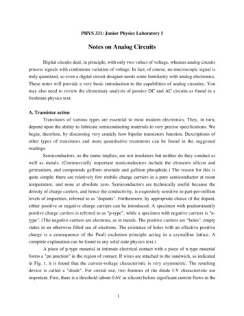
Experiment 2Electric Circuit FundamentalsIntroductionThis experiment has two parts. Each part will have to be carried out using the MultisimElectronics Workbench software. The experiment will then be repeated with hardwiredlaboratory equipment. The experiments involve measurement of voltage and current in a dccircuit and verification of ohm’s law.PART I: VOLTAGE AND CURRENT IN A DC CIRCUITObjectives1. Investigate how to use a voltmeter to measure voltage across a circuit component2. Investigate how to use an ammeter to measure current flow in a circuit component3. Investigate what happens if the rated value of a component is exceeded (onlysimulation will be used to investigate this step)MaterialsOne dc power supplyOne dc 0-20V VoltmeterOne dc 0-100mA AmmeterOne MultimeterOne 5V, 1W lampAmmeterVoltmeterFigure 1: Measuring current and voltage: a lamp connected across a battery10
ProcedureSimulation1. Construct the circuit shown in Figure 1 on the Multisim Electronics Workbench. Use5V, 1W lamp for simulation. (In the Components Toolbar select the Indicator icon;now find Voltmeter, Ammeter and Lamp in this window).2. Set the dc supply voltage to 3V and click the Simulate Switch and verify that thebattery voltage is 3V as measured by the voltmeter. Record the voltage across thelamp terminals ‘V’ and the current ‘I’ flowing through it in Table 1. Calculate powerdissipation in the lamp using the relationship P VI and note it down.3. Change the dc supply voltage to 5V. Run the analysis again. Record voltage andcurrent in Table 1 and calculate power dissipation in the lamp.4. Change the dc supply voltage to 7V. Run the analysis and see the effect on theintensity of light. Record voltage, current in Table 1 and calculate power dissipation.5. Change the dc supply voltage to 8V. Run the analysis and observe the value ofcurrent, also observe the glow of the lamp. What happened? ExplainTable 1: Simulation results using Multisim Electronics WorkbenchSource Voltage (V)Lamp Voltage (V)Current (A)Power , VI (W)357Note: The lamp is rated at 5V, 1WQuestion: Why the lamp is damaged when the voltage across it goes to 7V? Explain bycomparing power dissipation with rated value.Hardwired Experiment6. Build the circuit of Fig. 1 with hardwired laboratory components. Before switching onthe DC power supply set its voltage to 0 volts.7. Turn the power supply on. Increase the supply voltage to 3V. Enter the voltage andcurrent in Table 2.8. Increase the supply voltage to 5V and repeat step 7.Note: Do not raise the battery voltage beyond 5V as it will burn the lamp.11
Table 2: Hardwired experimental resultsSource Voltage (V)Lamp Voltage (V)Current (A)Power , VI (W)35Question: Compare the Multisim Electronics Workbench results with the hardwiredlaboratory ones. Comment on the results.PART II: OHM’S LAW - RESISTANCEObjectives1.2.3.4.Learn how to use multimeter to measure resistanceVerify Ohm’s lawDetermine the relationship for voltage and current for constant resistanceDetermine value of resistance from slope of I-V characteristic curve.MaterialsOne dc variable voltage power supplyOne multimeterOne 0-100mA AmmeterResistor (100Ω)I V1-Figure 2: Measuring resistanceFigure 3: Verifying Ohm’s Law12
ProcedureSimulation1. Build the circuit of Figure 2 using Multisim Electronics Workbench. Connect amultimeter between the terminals of resistor and set it to read resistance. SelectR1 100Ω. Click the Simulation Switch to run analysis. Record the value ofresistance R1 in Table 3.2. Build the circuit given in Figure 3. Set Vs 10V and R1 100Ω. Click SimulationSwitch to run analysis. Record voltage ‘V1’ across resistor R1 by connecting amultimeter in parallel to it. Record the value of current ‘I’ flowing through R1 byconnecting another multimeter in series to R1. Note down the values in Table 3. Fromthe voltage current readings verify Ohm’s law V1 R1 I. Considering multimeterreading as reference, calculate % error.3. Vary the dc supply voltage Vs in steps of 2V and record current in each case. Enteryour results in Table 4.4. Plot ‘I’ vs. ‘V’ in the graph of Table 5.5. Calculate the value of resistor based on the slope of the V-I characteristic curveplotted in step 4.Hardwired Experiment6. Repeat steps 1-5 with the laboratory hardwired components.Note: Use different color pen to plot the experimental results in Table 5.Table 3: Resistance MeasurementWorkbenchHardwired% ErrorOhmmeter ReadingR1 R1 Ohm’s Law (V1/I)R1 R1 Table 4: V-I measurementsV (volt)0246810WorkbenchI (mA)HardwiredV (volt)0246810I (mA)13
Table 5: V-I plotResistance Measurement from V-I slope Workbench experimentHardware experimentR R Questions1. Compare the values of resistance obtained with ohmmeter, Ohm’s law (V/I) and slope ofthe V-I plot. Comment on your results.2. How could you tell if the resistances are linear or not?Any other observations or comments14
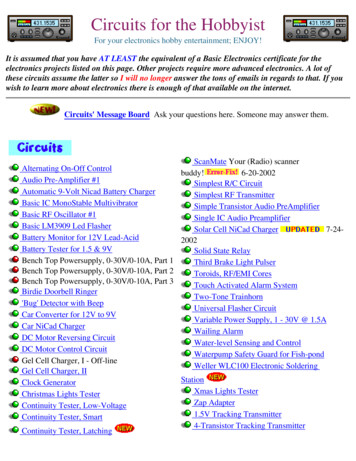
Experiment 3Resistors in Series, Color Codes & Power RatingIntroductionThis experiment is about measurement of resistance directly and also through voltage andcurrent measurement. The experiment has two parts – the first part using MultisimElectronics Workbench, and the second part through hardware components.PART I: RESISTORS IN SERIES (USING MULTISIM)Objectives1.2.3.4.5.Measure the equivalent resistance of a series circuitDetermine current in each resistorDetermine voltage across each resistorDetermine equivalent resistanceDemonstrate Kirchhoff’s voltage lawMaterialsOne dc voltage supplyOne multimeterFive dc 0-10 V voltmetersFive dc 0-5mA ammetersAssorted resistorsabFigure1. Measurement with multimeter15
abcedfgkjihFigure 2: Resistors in seriesProcedure1. Draw Figure 1 using the Multisim simulation software. Connect the multimeter asohmmeter between ‘a’ and ‘b’. Click the simulate switch to run analysis. Record themeasured resistance. Calculate the total value just by addition and record it.Req (measured) Req (calculated) Question: How did the measured value compare with the calculated value? Comment.2. Draw Figure 2. Run the simulation and record the currents and voltages.IabIcdIefIhiIjkVbcVdeVfgVghVij3. Based on the equivalent resistance Req calculated in step 1 and value of the voltage source(V), calculate the source current (Is).Is Question: How did the measured current Iab compare with the calculated current (I)?16
4. From the measured value of voltages across the resistances, calculate the current. Comparethese calculated values of currents with the measured values of currents.MeasuredCalculatedIabIcdIefIhiIjkIab Vbc/R1Icd Vde/R2Ief Vfg/R3Ihi Vgh/R4Ijk Vij/R5Question: How do they compare?5. Calculate the sum of the voltages Vbc, Vde, Vfg, Vgh, VijVbc Vde Vfg Vgh Vij .Question: What is the relationship between the supply voltage (VS) and the sum obtained?Does it confirm Kirchhoff’s law? Explain.PART II: RESISTORS, MEASUREMENTS AND COLOR CODES(HARDWIRED EXPERIMENT)Objectives1. Determine the resistance of a selection of carbon resistors by color codes.2. Compare values obtained with voltage current readings.3. Observe power dissipation property of carbon resistors.MaterialsDC power supplyDigital multimeterAssorted resistorsColor CodesThe approximate value of a carbon resistor can be found by 4 color bands on it. The 9 colorsin the sequence are black, brown, red, orange, yellow, green, blue, violet, grey and white.Carbon resistors may have a fifth band which indicates reliability of the resistor. Figure 3shows the color code structure.17
Example: Brown Red Orange Gold121035% 12 KΩ, 5%Procedure1. Get 5 carbon resistors of the same value as you used in Figure 1. Find the nominal valueand the tolerance of each resistance using the color codes and record in Table 1. Note therelation between the power rating and the physical size of the resistance.2. Using the digital multimeter as an ohmmeter, measure and record the resistance of eachresistor.3. Connect the circuit as shown in Figure 2. Set the source voltage to 12 V. Measure all thevoltages and currents and find the values of resistance using ohm’s law i.e. R V/I. Recordyour results in Table 1.Table 1: Resistor valuesResistorR1R2R3R4R5Color codesNominal valueToleranceOhmmeter readingV/I% deviation from nominal valueActual value within tolerance?Answer the Following Questions1. An electric heater takes 1.48 kW from a voltage source of 220 V. Find the resistance of theheater.2. If the current in a resistor doubles, what happens to the dissipated power? (Assume theresistor operates in the linear region).18
3. A 4Ω resistor is needed to be used in circuit where the voltage across the resistor is 3V. Iftwo 4Ω resistor with 1W and 3 W power rating are available, which one will you use andwhy?4. Consider a resistor with a positive temperature coefficient. The resistor operates at higherpower level than its rating when current of 1A passes through it. The resulting voltageacross the resistor in this case is 20V. If the current is increased to 1.1A, do you expect thevoltage to be:a. Less than 22V.b. Equal to 22 V.c. Higher than 22 V.Explain the reason for your expectation.Any other observations or comments19
Resistor Color Code ChartColor1st Band(1st Figure)2nd Band(2nd Figure)3rd 88108White991094th Band(Tolerance) 2%Gold10-1 5%Silver10-2 10%Figure 3: Resistor color codes20
Experiment 4Kirchhoff’s LawsIntroductionKirchhoff’s voltage law (KVL) states that the algebraic sum of all voltages around any closedpath equals zero. The Kirchhoff’s current law (KCL) states that the algebraic sum of all thecurrents at a node is zero (current entering a node has opposite sign to the current leaving thenode). This experiment studies these two laws using Multisim Electronics Workbench, thenwith actual hardwired circuit.Objectives1. Voltage current measurement in a dc circuit2. Verification of Kirchhoff’s voltage and current laws.MaterialsOne dc power supplyOne multimeterAssorted carbon resistorsFigure 1: Resistive circuitProcedure1. Construct the circuit shown in Figure 1 using Multisim Electronics Workbench.2. Measure the voltages VAB, VBC, VAD, VDC, VBD, and VAC. Enter the values in Table 1.Note the polarities of the voltages.3. Measure the currents IAB, ICB, IAD, ICD and IFA and enter the values in Table 2. Note thepolarity (sign) of the currents.21
4. Calculate the voltages around the following loops and record them in Table 4.ABCEFA, ABDA, BDCB, ABCDA5. Verify KCL by adding the currents at nodes A, B, C, D. Enter your results in Table 3.6. Construct the circuit in Figure 1 with hardware components. Repeat steps 2-5. Enter youresults in Tables1-4. Considering the Workbench results as the base compute thepercentage errors.Table 1: Voltage measurementVABVBCVADVDCVBDVACWorkbenchHardwired% ErrorTable 2: Current measurementIABICBIADICDIFAWorkbenchHardwired% ErrorTable 3: Sum of currents at nodesABCDWorkbenchExperiment% ErrorTable 4: Voltages around loopABCEFAABDABDCBABCDAWorkbenchExperiment% Error22
Answer the following Questions:1. Do the experimental and theoretical values of voltages and currents agree?2. Give possible reasons for any discrepancies.3. Are KVL and KCL verified?4. Give reasons for any discrepancies.Any other observations or comments23
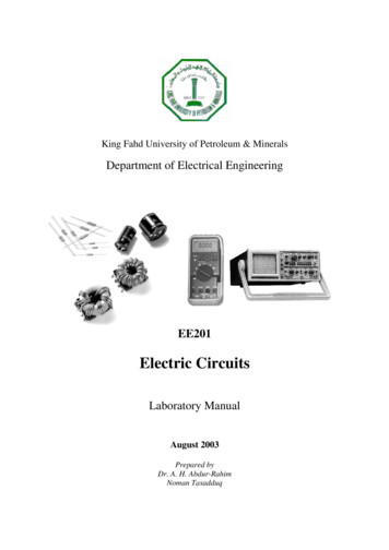
Experiment 5Series & Parallel CircuitsVoltage Divider & Current Divider RulesIntroductionFigure 1: Series circuitFigure 2: Parallel circuitFor a series circuit shown in Figure 1, the voltages across resistors R1, R2 and R3 can bewritten as,V1 R1VsR1 R 2 R 3V2 R2VsR1 R 2 R 3V3 R3VsR1 R 2 R 3(1)This is the voltage divider rule (VDR).For a parallel circuit given in Fig. 5.2, the branch currents can be written in terms of the totalcurrent as,I1 R2IsR1 R 2R1I2 IsR1 R 2(2)This is termed as the current divider rule (CDR).24
Objectives1. To study the voltage current relationships of series and parallel circuits2. To verify the voltage current divider and voltage divider rules.MaterialsOne dc power supplyOne multimeterAssorted resistorsFigure 3: Series-parallel circuit IFigure 4: Series-parallel circuit IIR2 100Ω, R3 150Ω, R4 220Ω, R6 330ΩProcedureSimulation1. Build the circuit given in Figure 3 on Multisim Electronics Workbench.2. Connect voltmeters, ammeters (or multimeters) at appropriate positions to measurevoltages and currents shown in Table 1.3. Disconnect the voltage source. Connect a mutimeter and measure the total resistanceand record the value in Table 1. (Remember resistance is always measured withoutany source connected to the circuit)4. Repeat steps 2 and 3 for the circuit given in Figure 4 and record the values in Table 2.Hardwired Experiment5. Build the circuit of Figure 3 with the hardwired components. Take the voltage currentmeasurements and Req and record in Table 1. Considering the Workbench results asthe base compute the percentage errors.6. Build the circuit of Figure 4 with the hardwired components. Take the voltage currentmeasurements and Req and record in Table 2. Considering the Workbench results asthe base compute the percentage errors.25
Table 1: Simulation and experimental results for Figure 3IsI2I3I4I5I6V2V3V4V5V6ReqV6ReqWorkbenchHardwired% ErrorTable 2: Simulation and experimental results for Figure 4IsI2I3I4I5I6V2V3V4V5WorkbenchHardwired% ErrorQuestionsRefer to Figure 3 and the results obtained in Table 1 and answer the following questions:1. Are R4 and R6 in parallel or in series? Why? Refer to voltage currentmeasurements for your answer to justify.2. Are R3 and R4 in parallel or in series? Why? Justify3. Are Vs and R3 in parallel or in series? Why? Justify4. Are Vs and R6 in series or in parallel? Why? Justify.5. Are Vs and Req. in parallel or in series? Why? Justify26
6. Is VDR applicable for applicable R3 and R4? Why? Justify your answer on thebasis of theory given in the introduction.7. Is CDR applicable for R4 and R6? Why? Justify your answer on the basis of theorygiven in the introduction.8. Is the parallel combination of R4 and R6 in series or in parallel with R2? Why?Justify.Refer to Figure 4 and the results obtained in Table 2 and answer the following questions:9. Are R4 and R6 in parallel or in series? Why? Refer to voltage currentmeasurements for your answer to justify.10. Are R3 and R4 in parallel or in series? Why? Justify11. Are Vs and R3 in parallel or in series? Why? Justify12. Are Vs and R6 in series or in parallel? Why? Justify.13. Are Vs and Req. in parallel or in series? Why? Justify14. Is VDR applicable for applicable R3 and R4? Why? Justify your answer on thebasis of theory given in the introduction.27
15. Is CDR applicable for R4 and R6? Why? Justify your answer on the basis of theorygiven in the introduction.16. Is the parallel combination of R4 and R6 in series or in parallel with R2? Why?Justify.Any other observations or comments28
Experiment 6Superposition TheoremIntroductionIf there is more than one source in an electric network, the response (voltage or current) canbe determined by considering one source at a time. The total response is the algebraic sum ofthe individual responses. This is known as the superposition principle. While determining theresponses with a particular source, all other sources have to be deactivated (voltage sourcesreplaced by short circuits and current sources by open circuit).Objectives1. To verify superposition principle using Multisim Electronics Workbench.2. To verify superposition with hardwired components.MaterialsTwo dc power sourcesOne multimeterAssorted resistorsFigure 1: Resistive circuit with two sourcesProcedureSimulation1. Construct the circuit in Figure 1 on Multisim Electronics Workbench. Put the metersin the appropriate places to read voltages across and currents through each resistor.2. Run the simulation. Record all the voltages and currents in the circuit and enter themin Table 1. You can use ammeters for current measurements, voltmeter for voltagemeasurements or multimeter for both.3. Note the current directions and voltage polarities shown in Figure 1.29
Table 1: Simulation results for voltage and current with both sources10 KΩ22 KΩ1 KΩ47 KΩ33 KΩVoltageCurrent4. Remove the 5-V source from the circuit. Replace it by a short circuit.5. Run the simulation. Measure the voltages and currents and record in Table 2.Table 2: Simulation results for voltage and current with the 10-V source only10 KΩ22 KΩ1 KΩ47 KΩ33 KΩVoltageCurrent6. Put the 5-V source back to the circuit. Remove the 10-V source and replace it by ashort circuit.7. Run the simulation. Record all the voltages and currents in the circuit. Enter them inTable 3.Table 3: Simulation results for voltage and current with the 5-V source only10 KΩ22 KΩ1 KΩ47 KΩ33 KΩVoltageCurrentQuestion: Check for superposition principle. Enter your observations here.30
Hardwired Experiment8. Repeat the procedure with hardwired circuit elements. Enter your results in below.Table 4: Experimental results with both the sources10 KΩ22 KΩ1 KΩ47 KΩ33 KΩVoltageCurrentTable 5: Experimental results with 10-V source only10 KΩ22 KΩ1 KΩ47 KΩ33 KΩVoltageCurrentTable 6: Experimental results with 5-V source only10 KΩ22 KΩ1 KΩ47 KΩ33 KΩVoltageCurrentQuestions:1. Compare the results obtained with Workbench with those from hardware circuit, andcomment.2. Superposition theorem applies for only certain types of circuit. State what is the type?31
3. Superposition applies to only some variables or quantities like current and voltage. Itdoes not apply to, for example, power. State why not.Any other observations or comments32
Experiment 7Thevenin’s Theorem and Maximum Power TransferIntroductionA two terminal network resistive network can be replaced by a voltage source in series withan equivalent resistor. The value of the source voltage equals the open circuit voltage of thetwo terminals under consideration. The value of the equivalent resistor equals the resistancemeasured between the open terminals when all the sources of the circuit are deactivated(voltage source shorted and current source opened). This is termed as the Thevenin’stheorem. The voltage source is called Thevenin’s voltage (ETH) and the equivalent resistor,the Thevenin’s resistance (RTH).The maximum power output to a variable output resistance occurs when the value of theoutput resistance equals the Thevenin’s resistance.Figure 1: Maximum power output conditionThe value of the maximum output power or transferred power is given as,2E THPo 4R THObjectives1. To construct Thevenin’s equivalent using Workbench.2. To verify the equivalent obtained in step 1 using hardwired components.3. To determine maximum power transfer condition experimentally.MaterialsTwo dc power sourcesOne multimeterAssorted resistorsOne decade resistor33
Figure 2: Circuit for Thevenin’s equivalentProcedureSimulation1. Construct the circuit given in Figure 2 on Multisim Electronics Workbench.2. Remove the load resistor RL and connect a multimeter (or voltmeter) to read the opencircuit voltage between A and B. Simulate and record the voltage. This is ETH for thiscircuit between A and B.3. Remove the 10-V source. Replace it by a short circuit.4. Remove the 5-V source. Repl
appears just above the ground, this is called junction.When 2 or more components are connected at one point, a junction is created.A junction can also be place d manually by pressing Ctrl J or selectingEditàPlace Junction . This can be used to control the connection points manually. Also otice the ground node is automatically given noden