Transcription
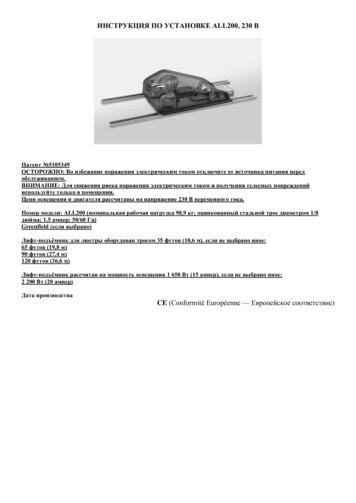
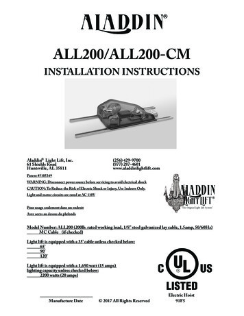
ALL200INSTALLATIONINSTRUCTIONSAladdin Light Lift, Inc.(901) 385-04568370 Wolf Lake Drive, Suite 112(877) 287-4601Memphis, TN 38133 www.aladdinlightlift.comPatent #5105349WARNING: Disconnect power source before servicing to avoid electrical shockCAUTION: To Reduce the Risk of Electric Shock or Injury, Use Indoors Only.Light and motor circuits are rated at 110VNot suitable for air handling spacesPour usage seulement dans un endroitAvec acces au dessus du plafondsModel Number: ALL200 (200lb. rated working load, 1/8” steel galvanized lay cable, 1.5amp, 50/60Hz)Greenfield (if checked)Light lift is equipped with a 35’ cable unless checked below:65’90’120’Light lift is equipped with a 1,650 watt (15 amps)lighting capacity unless checked below:2200 watts (20 amps)Manufacture DateElectric Hoist91F5
Read the following guidelines prior to installing the ALL200:I. The ALL200 must be installed by a licensed, bonded and insured electrician.II. The ALL200 must be installed level, in an accessible location and directly above the chandelier.III. Thoroughly read, understand and follow each step and safety warning in the ALL200 installationinstructions and orange safety precautions supplement.IV. During installation of the ALL200, take one step at a time and check off each step upon completion.V. The Troubleshooting Guide is located in the back of the Installation Instructions. Call Aladdin LightLift (877) 287-4601 if assistance is needed for installation and/or operation of the ALL200. Refer to theKeyswitch Controller Guide or Smartlift Controller Guide for operation instructions.VI. Ignoring any safety warnings and/or symbols not only voids the warranty, but may cause death, personalinjury and/or property damage.VII. The wattage of the chandelier can not exceed the wattage capacity of the ALL200.VIII. The Warranty Agreement is located on the last page of Installation Instructions.IX. Give all Aladdin paperwork to property owner and/or anyone that will be using ALL200.ALL200 Parts Bag ListA. #10 x 1 ¼” Pan Phillips-Wood Screws(QTY 4)B. 3/16” x 1” Fender Washers(QTY 4)C. Screw Collar Ring(QTY 1)D. Thread Lock(QTY 1)E. 3/32” Allen Wrench(QTY 1)
STEP 1Determine where ALL200 will mount on ceiling joists. ALL200 must be installed level, in an accessiblelocation directly above chandelier.Never mount the ALL200 off plane or unlevel in a standard installation. This could cause the chandelierto fall, which could cause death, personal injury, and/or property damage. The winch cable must hangplumb through the center of the top contact plate on the ceiling box.Never install the ALL200 where the ceiling height exceeds five feet less than the exact length of winchcable. For example, if the ALL200 is equipped with a 35ft. cable, do not install the ALL200 in a ceilingthat is greater than 30ft. This could cause the cable to become reverse wrapped on the winch. AnALL200 installed with a reverse wrapped cable could cause the chandelier to fall, which could causedeath, personal injury, and/or property damage. Winch cable length can be found on the ALL200product sticker, shipping box and the front page of these installation instructions.STEP 2After turning off power, remove and discard existing electrical box if present in ceiling. Only use ceiling boxprovided with ALL200. See Diagram A.Never remove an existing ceiling box while the power is connected. Electricity could cause death,personal injury, and/or property damage.STEP 3Cut a 4 ½” hole in ceiling for ceiling box. If you removed an existing ceiling box, existing hole may need tobe enlarged.STEP 4Attach conduit assembly to 3/4” conduit connector mounted below pulley. Once completely inserted,tighten set screw on conduit connector. See Diagram A.Never attach or adjust the conduit assembly improperly. This could interfere with the automatic shutoffsystem and could cause the chandelier to fall, which could cause death, personal injury, and/or propertydamage.Diagram A3/4” Conduit ConnectorTelescopic Conduit AssemblyALL200 Ceiling Box
STEP 5Attach the 1/2” conduit connector on ceiling box to bottom of conduit assembly. Once completely inserted,tighten set screw on conduit connector. See Diagram B.Never attach or adjust the conduit assembly improperly. This could interfere with the automatic shutoffsystem and could cause the chandelier to fall, which could cause death, personal injury, and/or propertydamage.Diagram B1/2” Conduit ConnectorSTEP 6Tighten temporary five pound weight to fixure coupler on bottom contact plate. Make sure jam nut onweight is tight.Never install or operate an ALL200 before securing the temporary five pound weight to the fixturecoupler. This could cause the temporary weight to fall, which could cause death, personal injury, and/orproperty damage.
STEP 7Position ALL200 where ceiling box will be centered in ceiling hole. Weight and bottom contact plateassembly should hang down through ceiling hole. Adjustments can be made loosening 3/8” channel strutbolts that hold ALL200 to channel struts. Retighten channel strut bolts after adjustments are made.Confirm channel strut nuts are seated properly. See Diagram C.Never adjust the channel struts improperly. This could cause the chandelier to fall, which could causedeath, personal injury, and/or property damage.3/8” Channel StrutAdjustment BoltsDiagram C3/8” Channel StrutAdjustment BoltsSTEP 8Adjust ceiling box elevation up or down to be flush with sheetrock. Use 3/32” Allen wrench on conduitcoupler to loosen bottom set screw. Conduit assembly is telescopic. The ceiling box should not touch insideof ceiling hole. Retighten bottom set screw on conduit coupler and confirm top set screw is tight. SeeDiagram D.Never attach or adjust the conduit assembly improperly. This could interfere with the automatic shutoffsystem and could cause the chandelier to fall, which could cause death, personal injury, and/or propertydamage.Diagram DConduit CouplerTop Set Screw3/32” AllenWrenchConduit CouplerBottom Set Screw3/32” Allen WrenchSheetrockSheetrock4 1/2” Hole
STEP 9Shim and adjust ALL200 so that winch cable hangs plumb through center of hole in top contact plate onceiling box. See Diagram E. Look up at ceiling box from floor level to verify cable is plumb.Never install the ALL200 where the cable is not plumb through the center of the ceiling box. This couldinterfere with the automatic shutoff system and could cause the chandelier to fall, which could causedeath, personal injury, and/or property damage.Diagram EView from Floor LevelConfirm winch cablehangs plumb throughcenter of hole intop contact plate onceiling box.STEP 10Fasten ALL200 to floor joists using wood screws (part A) and washers (part B) included in parts bag. SeeDiagram F.Never install the ALL200 without properly fastening it to the floor joists. This could interfere withthe automatic shutoff system and could cause the chandelier to fall, which could cause death, personalinjury, and/or property damage.Diagram FWood ScrewsWashers
STEP 11Turn off supply power before wiring ALL200. Turn off motor switch in square box. Wire motor switchwith 110V wiring. The 110V motor feed must be kept separate from 110V light switch leg. Keep motorand light neutrals separate. The motor neutral is white and 14 gauge. See Diagram G.Never wire the ALL200 improperly. Make sure electricity is turned off when installing and/orperforming maintenance on the ALL200. Improper wiring and/or electricity could cause death,personal injury, and/or property damage.STEP 12Turn off supply power before wiring ALL200. Turn off light switch in square box. Wire light switch with110V wiring. The 110V light switch leg can not be used as motor feed. Keep light and motor neutralsseparate. The light neutral is white and 12 gauge. If wired properly, a dimmer may be used. Wire a twocircuit light package on seperate phases for lights (2 hots - 1 neutral). See Diagram G.Never wire the ALL200 improperly. Make sure electricity is turned off when installing and/orperforming maintenance on the ALL200. Improper wiring and/or electricity could cause death,personal injury, and/or property damage.Diagram G12 Gauge Light Neutral14 Gauge Motor Neutral12 Gauge Light Hot14 Gauge Motor HotLightHot Light SwitchLeg 110VNeutral LightSwitch Leg 110VMotor110V House HotFor Motor110V House NeutralFor Motor
STEP 13Remove dust cover and remove paper tape from winch drum while keeping tension on winch cable.Never operate the ALL200 without tension on the cable. Never remove or tamper with the cable safetydevice. Never install an ALL200 that has the cable safety device removed or tampered with. The cablesafety device consists of the limit switch and small gauge rectangular wire. It is located directly in frontof the winch drum. Removing or tampering with the cable safety device could cause the cable to becomereversed wrapped on the winch. This could also cause the cable to unravel off the winch drum and getdamaged. Never install or operate an ALL200 that has a frayed, kinked, or otherwise damaged cable.Never operate the ALL200 without first removing the paper tape from the winch drum. Avoiding any ofthese safety warnings could cause the chandelier to fall, which could cause death, personal injury, and/orproperty damage.STEP 14Replace dust cover and locate controller wire. Controller wire is a low voltage, gray sheathed, four conductorwire with white plugs on either end.STEP 15Run controller wire in to single gang box for Keyswtich Controller or optional SmartLift Controller.Chandelier must be visible from controller location.STEP 16If using a Keyswitch Controller instead of a SmartLift Controller, secure key cylinder to cover plate usingsupplied keyswitch nut.Plug controller to controller wire. Use supplied cover plate screws to attach controller to single gang box.STEP 17Test motor and automatic shut-off system of ALL200. For operation instruction, reference KeyswitchController Guide or SmartLift Controller Guide, then follow below:Run ALL200 down a few inches. Run ALL200 up to CEILING POSITION. When ALL200 pullsbottom contact plate and temporary weight to CEILING POSITION, the motor will, if installed andmounted properly, shut off by itself.Call Aladdin Light Lift (877) 287-4601 immediately if ALL200 does not shut off at CEILINGPOSITION.Never extend the full length of winch cable from the ALL200. This could cause the cable to becomereverse wrapped on the winch. An ALL200 installed with a reverse wrapped cable can cause thechandelier to fall, which could cause death, personal injury, and/or property damage. Refer to theKeyswitch or SmartLift Controller tag for correct operating instructions. Winch cable length can befound on the ALL200 product sticker, shipping box and the front page of these installation instructions.STEP 18Run ALL200 down until temporary weight is at desired elevation to hang chandelier.STEP 19Holding tension on cable, unscrew weight from fixture coupler.Never operate the ALL200 without tension on the cable. This could cause the cable to wind off thewinch drum and get damaged. A damaged cable could cause the chandelier to fall, which could causedeath, personal injury, and/or property damage.
STEP 20Fully thread screw collar loop or threaded stem that was supplied with chandelier to 1/4 IPS fixture coupler.If chandelier was supplied with a 1/8 IPS, 3/8 IPS, or 1/2 IPS screw collar loop or threaded stem, contactAladdin Light Lift (877) 287-4601 to obtain proper coupler. See Diagram H.Never install a chandelier on an ALL200 using metric threaded fittings. They will not thread togetherproperly and could cause the chandelier to fall, which could cause death, personal injury, and/orproperty damage. Only use IPS threaded fittings.Never hang a chandelier from an ALL200 using anything but the Aladdin Light Lift supplied fixturecoupler, bottom contact plate, and dowel pin. This could cause the chandelier to fall, which could causedeath, personal injury, and/or property damage.STEP 21Attach chandelier canopy to screw collar loop using screw collar rings on both top and bottom. An extrascrew collar ring (part C) is supplied in parts bag. See Diagram H.Diagram H1/4 IPS Fixture CouplerCanopyThreaded Stem/Screw CollarLoop Supplied withChandelierScrew Collar RingsSTEP 22Adjust chandelier chain to desired length and attach to screw collar loop.Never cut, modify, or adjust the winch cable and never install an ALL200 with a cut, modified oradjusted winch cable. Adjust the chandelier elevation by adjusting the chandelier chain or stem. AnALL200 installed with a cut, modified, or improperly adjusted cable could cause the chandelier to fall,which could cause death, personal injury, and/or property damage.
STEP 23Adjust screw collar rings so top of canopy is just below edge of bottom contact plate. Canopy should be atleast 1 ¾” deep. See Diagram I.Never allow the chandelier canopy to make contact with the ceiling before the contact plates meet. Thiscould interfere with the automatic shutoff system and could cause the chandelier to fall, which couldcause death, personal injury, and/or property damage.STEP 24Loosen bottom screw collar ring to allow easy wire access. See Diagram I.STEP 25Run chandelier wires through screw collar or threaded stem and pull through fixture coupler holes. SeeDiagram I.STEP 26Wire nut chandelier hot wire to black bottom contact plate wire, neutral to white, and ground to green.If the chandelier has two hot wires, wire extra hot to red wire. See Diagram I. Bare ground wire fromchandelier can not touch underside of bottom contact plate. A direct short will occur.Diagram ITop of CanopyJust Below Edgeof BottomContact PlateWire Nut ChandelierWires to BottomContact Plate Wires1¾” DeepCanopyBottom ScrewCollar RingPull ChandelierWires ThroughScrew Collar Loop/Threaded Stem andFixture Coupler
STEP 27Tighten fixture coupler set screws using supplied 3/32” Allen wrench. Fixture coupler set screws havethread lock already applied at factory. See Diagram K.STEP 28Apply supplied liquid thread lock (part D) to all fittings including fixture coupler and screw collar loopfittings.Never attach the chandelier to the ALL200 improperly. Failure to secure the fixture coupler set screwsand properly apply thread lock could cause the chandelier to fall, which could cause death, personalinjury, and/or property damage.STEP 29Replace canopy and bottom screw collar ring. Confirm top of canopy is just below edge of bottom contactplate. See Diagram K.Never allow the chandelier canopy to make contact with the ceiling before the contact plates meet. Thiscould interfere with the automatic shutoff system and could cause the chandelier to fall, which couldcause death, personal injury, and/or property damage.Diagram KTop of CanopyJust Below Edgeof BottomContact PlateCanopyTighten SetScrews with3/32” AllenWrenchBottom Screw Collar RingSTEP 30Confirm winch cable still hangs plumb through center of hole in top contact plate on ceiling box. SeeSTEP 9 and Diagram E.STEP 31Operate ALL200 to the CEILING POSITION. Test lights and call Aladdin Light Lift (877) 287-4601with any questions regarding installation and/or operation of ALL200.
ALL200 TROUBLESHOOTING GUIDETECH SUPPORT: (877) 287-4601 Monday through Friday 8:00am to 4:00pm CSTI. Troubleshooting and installation must be performed by a licensed, bonded, and insured electrician.Electricity can cause death, personal injury, and/or property damage.II. Prior to troubleshooting or installation, read, understand and follow each safety warning in the ALL200installation instructions and safety precautions supplement. Failure to follow Aladdin’s safety precautionsand/or warnings could cause the chandelier to fall, which could cause death, injury, and/or property damage.SYMPTOM: ALL200 DOES NOT OPERATE:Once ALL200 is installed per the installation instructions, use the following steps to troubleshoot.1. Confirm motor switch in the square box is turned on. The square box is mounted on the chassis plate ofthe ALL200, right in front of the control board. If it was found in the off position, flip it to the on positionand use the controller to test the ALL200. If ALL200 still does not operate, proceed to step 2.2. Turn the motor and light switch in the square box to the off position. Confirm motor fuse is good. Themotor fuse is held to the control board by fuse clips and is located right in front of the motor assembly.Remove and perform a continuity test on the motor fuse. If the fuse reads continuity, place it back in thefuse clips. If it does not read continuity, it must be replaced with a good, 1.6 amp, slow blow fuse. Turn themotor and light switch in the square box to the on position, and use controller to test the ALL200. If theALL200 still does not operate, proceed to step 3.3. Turn the motor and light switch in the square box to the off position. Confirm limit switch wires areattached properly. Confirm the limit switch wires are properly connected to the limit switch as well as thelimit switch terminals on the control board. The limit switch is located on top of the ceiling box. The whitelimit switch wire should be plugged from COM on the control board to the single terminal side of onelimit switch. The green limit switch wire should be plugged from NO on the control board to the top limitswitch terminal on the double terminal side of the limit switch. The red limit switch wire should be pluggedfrom NC on the control board to the bottom limit switch terminal on the double terminal side of the limitswitch. If limit wires were found plugged incorrectly, plug them to their corresponding terminal and use thecontroller to test the ALL200. If the ALL200 still does not operate, proceed to step 4.4. From where the ALL200 is installed, call Aladdin Light Lift technical support Monday through Fridayduring normal business hours at (877) 287-4601. Two jumper wires and a voltage meter will be needed tofurther test the ALL200.SYMPTOM: CHANDELIER WILL NOT LIGHT:Once the ALL200 is installed per the installation instructions, use the following steps to troubleshoot.Note: If the top contact plate is painted, the chandelier will not light.1. Confirm ALL200 is at the CEILING POSITION. If not, use the controller to operate the ALL200 tothe CEILING POSITION. Chandelier will only light at the CEILING POSITION. If operated to theCEILING POSITION and the chandelier will still not light, proceed to step 2.2. Confirm light switch in the square box is turned on. The square box is mounted on the chassis plate ofthe ALL200, right in front of the control board. If it was found in the off position, flip it to the on positionand to test the chandelier. If chandelier still does not light, proceed to step 3.
ALL200 TROUBLESHOOTING GUIDE cont.3. Turn the motor and light switch in the square box to the off position. Confirm light fuse is good. Thelight fuse is held to the control board by fuse clips and is located right in front of the light relay. Removeand perform a continuity test on the light fuse. If the fuse reads continuity, place it back in the fuse clips.If it does not read continuity, it must be replaced with a new, 15 amp, fast blow fuse. If the ALL200 wasequipped with a 2200 watt upgrade package, replace with a new, 20 amp, fast blow fuse. Turn the motorand light switch in the square box to the on position, and test the chandelier. If the chandelier still does notlight, proceed to step 4.4. From where the ALL200 is installed, call Aladdin Light Lift technical support Monday through Fridayduring normal business hours at (877) 287-4601. A voltage meter will be needed to further test theALL200.SYMPTOM: ALL200 WILL NOT SHUT OFF PROPERLY AT CEILING POSITION:Discontinue use immediately and contact Aladdin Light Lift at (877) 287-4601.Warranty AgreementAladdin Light Lift, Inc. warrants its chandelier light lift unit for one year from the date ofpurchase. The warranty includes all parts provided the unit is installed properly by a licensedelectrician. Labor charges will be the responsibility of the purchaser. If the unit does not operateproperly, the purchaser must contact a factory authorized service technician approved by AladdinLight Lift, Inc. to determine if the unit was installed properly. The technician will furnish a writtenreport to the purchaser and Aladdin concerning any problem with the lift system which will bebinding on all parties concerned. All defective parts must be returned to Aladdin Light Lift, Inc.for the warranty to apply. Any alteration or by-passing of the electrical or mechanical system ofexceeding the wattage maximum (as indicated on the lift) will void the warranty and can result inan electrical hazard. This warranty agreement showing date of purchase and distributor must befilled out at www.aladdinlightlift.com/warranty-card.php within 30 days of purchase to validate thewarranty. Call your distributor to obtain the name of a factory authorized technician in your area.
IV. During installation of the ALL200, take one step at a time and check off each step upon completion. V. The Troubleshooting Guide is located in the back of the Installation Instructions. Call Aladdin Light Lift (877) 287-4601 if assistance is needed for