Transcription
IEEE TRANSACTIONS ON POWER DELIVERY, VOL. 25, NO. 1, JANUARY 201081Detection of Symmetrical Faults by DistanceRelays During Power SwingsSaeed Lotfifard, Student Member, IEEE, Jawad Faiz, Senior Member, IEEE, and Mladen Kezunovic, Fellow, IEEEAbstract—For maintaining security of distance relays, powerswing blocking is necessary to prevent unintended operation underpower swings. To be dependable, distance relays must operatewhenever a fault occurs. Therefore, detecting faults during powerswings is an important issue since the relay should be able to differentiate the fault condition and not be blocked during that time.This paper presents a new method for detecting a symmetricalfault during a power swing, based on extracting components ofthe current waveform using the Prony method. The merit of themethod is demonstrated by simulating different faults duringpower swing conditions using the Alternate Transients Programversion of the Electromagnetic Transients Program.Index Terms—Distance relay, power swing, prony method, symmetrical fault.I. INTRODUCTIONISTANCE relay used for transmission line protection isdesigned to trip if the line faults occur within the specifiedzone. It is not supposed to trip during the power swing causedby the disturbances outside the protected line [1]. In order toavoid an unintended operation, power swing blocking functionis used.Conventional power swing blocking method is based ontiming the movement of the measured impedance throughthe zones of the relay. During the fault conditions calculated (apparent) impedance moves along the locus almostinstantaneously. However, under power swing conditions theimpedance moves slowly, typically takes hundreds of milliseconds before approaching the relaying zones. The time delayfor discriminating fault from power swing has to be set withknowledge of the likely speed of movement of the impedanceduring the power swing, so it is possible that relay fails to blockif the apparent impedance moves too fast. Moreover, the relaymay not respond to genuine faults occurring during the powerswing period since it is blocked from operation [2], [3]. Thiswill inevitably delay the operation of relay when a fault occursduring the power swings. Therefore, fault detection duringpower swing is an important issue [4].Presence of negative and zero sequence components due toasymmetrical faults, which do not exist during the stable powerDswing, makes it possible to detect fault during the power swing.However, there are no such components during symmetricalfault. Some symmetrical fault detectors are based on the superimposed components or the rate-of-change of measuredimpedance. The issue related to these methods is inability tooperate sensitively for the faults that cause very small superimposed components, such as the ones that happen at the powerswing center and the power angle close to 180 [5].Magnitude of the swing-center voltage (SCV), defined as thevoltage at the location of a two-source equivalent system wherethe voltage value is zero and the angles between the two sourcesare 180 apart, is used to distinguish faults from power swing[6]. However, it is difficult to set the threshold, especially whena fault arc is considered.In [7] and [8], a method based on the monitoring of thevoltage phase angle at the relay location is proposed to discriminate fault from power swing. Only the single-phase faultshave been simulated and the method has not been applied tosymmetrical faults [9].In [10], an adaptive neuro-fuzzy inference systems (ANFIS)based method has been proposed. The method needs a hugenumber of training patterns to be produced by simulations ofvarious cases. Moreover, it might need re-training for use in different power systems.A wavelet-based signal processing technique is an effectivetool for power system transient analysis and feature extraction[11], [12]. In [9], the wavelet transform (WT) has been utilizedfor detecting fault during the power swing. It is based on thepresence of high frequency signal components created at theinception of the fault. The implementation needs high frequencysampling.This paper presents a new symmetrical fault detector for distance relay that avoids the disadvantages of previous schemeswhile it maintains the required selectivity. This detector is basedon the extraction of the current waveform components using theProny method, which is briefly described first. Proposed algorithm that detects faults by monitoring the presence of decayingdc in current waveform is discussed next. Finally, the performance of the proposed scheme is studied by simulating variousfaults and power swing cases using ATP version of EMTP.II. PRONY METHODManuscript received June 09, 2009. First published December 08, 2009; current version published December 23, 2009. Paper no. TPWRD-00071-2009.S. Lotfifard and M. Kezunovic are with the Department of Electrical andComputer Engineering, Texas A&M University, College Station, TX 778433128 USA (e-mail: s.lotfifard@neo.tamu.edu; keza@verizon.net).J. Faiz is with the Center of Excellence on Applied Electromagnetic Systems,School of Electrical and Computer Engineering, University of Tehran, Tehran1439957131, Iran (e-mail: jfaiz@ut.ac.ir).Digital Object Identifier 10.1109/TPWRD.2009.2035224The Prony method is a tool that has been used in signal processing applications and recently has been introduced to thepower system protection field [13], [14]. This method is considered a powerful tool for analyzing a signal and extracting itsmodal information. The fact that the Prony can handle dampedsignals and estimate the damping coefficient makes it suitablefor applications based on properties of power system transients.0885-8977/ 26.00 2009 IEEE
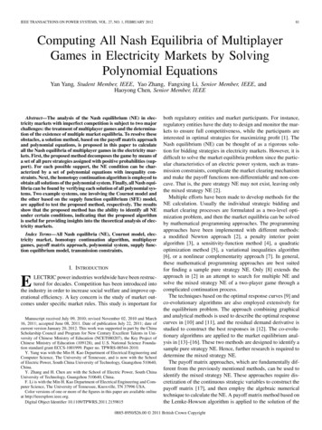
82IEEE TRANSACTIONS ON POWER DELIVERY, VOL. 25, NO. 1, JANUARY 2010Fig. 1. Sliding data window.Fig. 2. Estimated amplitude of fundamental component with different datawindow lengths.Prony calculates the modal information, such as frequency,amplitude, damping, and phase shift; these can be used to reconstruct the original signal or to make inferences about thesystem conditions that affected the signal. The fact that Pronycan be used for system stability and protection purposes makesit a good candidate for the modern concept of wide-area protection and emergency control [15].The Prony analysis directly estimates the parameters of theuniformly sampled signal by fitting a sum of complex dampedsinusoids as follows:(1)amplitude of component i;damping coefficient of component i;phase of component i;Fig. 3. Step response of second order Butterworth low pass filter with cut offfrequency of 1 kHz.frequency of component i;total number of damped exponential components.The Prony problem is formulated by knowing the value ofthe signalin the form of a series of time samples. Theproblem is solved to estimate the value of parameters of theProny method such that the squared errors of the fit are minimized. The mathematical details explaining the approach havebeen reported in [16].In order to calculate waveform components from the relaypoint of view, windowed-Prony method is used. Fig. 1 showsthis approach. Waveform components are calculated in eachwindow and they are updated as a new sample comes and theoldest gets dropped. Using shorter window makes the processfaster but reduces the accuracy. The window should be shortenough to achieve reasonable speed and long enough to reachdesired accuracy.Fig. 2 shows the estimated amplitude of fundamental component of the following signal with different data window lengths:(2)Although half a cycle window is faster, it has abrupt changesduring transient conditions. Two-cycle window has a long delay.One cycle window does not have such a delay, while it does notchange too abruptly like half a cycle window. As a result, in thispaper one cycle is chosen for data window length.As the proposed method is not based on high frequency component of signal, it does not need very high sampling frequency.Therefore, sampling frequency of 3 k Hz (50 samples per cycle)is selected which means interval between two samples in Fig. 1is 0.33 ms.In order to avoid aliasing phenomena in processing of thesignal, anti aliasing filter is used [17]. To satisfy the Nyquistcriterion, frequencies higher than one-half of the sampling frequency should be removed from the signal. It means cut-off frequency ( 3 dB) of the anti aliasing filter should be set at lessthan half a sampling frequency. In practice, such a filter cannotremove all unwanted frequencies, so the cut-off frequency of thefilter is set at about one third of the sampling frequency [18]. Theanti aliasing filter selected in this paper, is Butterworth low passfilter which is used commonly in protective relaying [19] Fig. 3shows step response of the second order Butterworth low passfilter with cut-off ( 3 dB) frequency of 1 kH.III. PROPOSED ALGORITHMFig. 4 shows a typical current waveform during a powerswing. During power swings in a two-machine system, the
LOTFIFARD et al.: DETECTION OF SYMMETRICAL FAULTS83Fig. 5. Thevinin equivalent of a faulted system.Fig. 4. Typical current waveform during power swing.current in the transmission lines is composed of two sinusoidalcomponents that can be given as follows:(3)where ,are the amplitudes of the two sinusoidal compoare the two unknown frequencies and ,arenents, ,the initial phase angles.It is easily shown that the following equation holds for addingtwo sine functions:Fig. 6. Voltage and current conditions during the first 1/2 cycle after arc initiation.(4)By solving (10), the current will be as follows:where(5)(6)(11)(7)Using the (4)–(7), (3) can be written as follows:(8)is obtained according to (5) by substituting and withand respectively. is yielded by solving (6) and (7) in whichis.If is almost equal to , which usually is the case, (3) can, thebe written in a simpler form. Assuming thatcurrent signals can be written as follows:(9)whereis the frequency of the current envelope andis the mean frequency of the sampled current.isandis[20]. Equations (8) and(9) express Fig. 4 in mathematical form, which is a sinusoidalwaveform with modulated amplitude that varies with time.Fig. 5 shows the Thevenin equivalent of a fault in a powersystem. Applying Kirchhoff’s voltage law leads to the followingdifferential equation [21]:(10)It is well known that power systems are exposed to faults involving arc phenomena. The arc current can be described usingthe process presented in [22]. According to Fig. 6 [22] whichshows the arc voltage and current, after arc initiation, the first. Beginning at this pointvoltage zero crossover occurs atthe voltage across the arc equals the system driving voltage.When the voltage reaches the value , the arc will re-strike.and the voltage will quickly decrease to the arc voltageCurrent, i, will begin to flow in the circuit and will increase as. When,long as the driving voltage, e, exceedsthe current is at its maximum and it will begin to decrease. Thecurrent is mathematically proportional to the volt-time area Aminus volt-time area B for any time t.When the volt-time area A equals to the volt-time area B, asshown by the shaded area in Fig. 6, the current will be zero, thearc will extinguish, and the arc voltage will quickly be equalto the driving voltage again. If the driving voltage at this pointthe arc re-strikes immediately andis equal or larger thanthe current wave becomes sinusoidal, so amplitude and shapeof the arc current become identical to those of the short-circuitcurrent [23]. But if it is below ers, the arc will not re-strike.When the voltage across the arc reaches ers once again the arcwill re-strike on the negative half cycle which will be a mirrorimage of the positive half cycle [22].
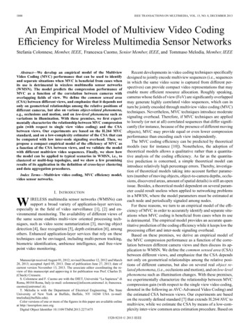
84IEEE TRANSACTIONS ON POWER DELIVERY, VOL. 25, NO. 1, JANUARY 2010Fig. 7. Thevenin equivalent of faulted circuit with arc included.Fig. 9. Current waveforms due to three-phase fault.Fig. 8. Schematic of a simulated power system.A mathematical expression for the arc current can be derivedusing the Thevenin equivalent circuit of electrical system withthe arc included, as shown in Fig. 7 [22]. Current i(t) can becalculated as follows:(12)wherearctan (X/R);Z;Xsystem inductive reactance;Rsystem resistance.According to (8), (9), (11) and (12), fault current comprises adecaying dc part, while there is no such a part in current waveform during pure power swing. Therefore, presence of decayingdc in current waveform can be used as a sign for detecting fault., then there isIt is noticeable that if in (11)no decaying dc in the current waveform in the phase under study.As there is 120 degrees phase shift between different phases inthree-phase system, there is a decaying dc in other phases. Thepresence of decaying dc at least in one phase implies that thefault has occurred and the relay must be unblocked.IV. SIMULATION RESULTSTo investigate the merit of the proposed algorithm, a powersystem shown in Fig. 8 [9] is modeled using ATP version ofEMTP. The system details have been given in [9].The distance relay located at breaker B1 is considered here.A fault happens at 0.1 s on Line-B and is cleared 0.08 s later byopening breakers B5 and B6. This causes the system to go intoa power swing. Three-phase faults are now simulated at variouslocations on line-A at different time instants.Fig. 10. Amplitude of decaying dc versus time during three-phase fault.Since the method depends on the relationship between faultsand occurrence of decaying dc component in the signals, thisbehavior should be investigated and demonstrated. The decaying dc component depends on many factors in the networkand hence it needs to be shown that the scheme is selectiveunder all such factors. The time constant and amplitude of thedecaying dc are unknown and depend on the fault resistance,fault position and the fault incipient time [24]. The effect ofthese factors was studied and in all cases the selectivity of theproposed method was proven.Detailed studies of two typical cases and results of some othercases are presented below and in Table III.happens atIn the first case, a three-phase fault withtime instant of 1 s, distance of 30 km from the relay and pre-fault. Fig. 9 shows currents due to thepower angle ofthree-phase fault.Fig. 10 shows amplitude of decaying dc component of thecurrent waveform of phase c at each time window. It is clear thatamplitude of decaying dc component increases after inceptionof the fault.
LOTFIFARD et al.: DETECTION OF SYMMETRICAL FAULTS85TABLE ICURRENT WAVEFORM COMPONENTS DURING THREE-PHASE FAULT ANDPOWER SWINGFig. 12. Amplitude of decaying dc versus time during three-phase fault including arc.TABLE IICURRENT WAVEFORM COMPONENTS DURING THE THREE-PHASE FAULTWHILE ARC IS INCLUDED AND POWER SWINGFig. 11. Current waveforms due to three-phase fault while arc is included.Table I shows current waveform components during one datawindow for three-phase fault and power swing.The values have been shown in the order of the amplitudevalues.In Table I, the values are components of current waveformsduring one data window (50 samples) of the signal. For instancefor Ia, in presence of three-phase fault, components that buildup the current waveform in that interval (one window) are asfollow: a sine function with frequency of 59 Hz ( 60 Hz) withand damping of(refer to (1)) and deamplitude ofand dampingcaying dc (frequency of 0) with amplitude ofand so on.ofAccording to Table I and Section III, in the case of the faultthere is decaying dc at least in two phases while there is nodecaying dc during power swing. Therefore, in order to detectfault during power swing, current waveform components arecalculated using Prony method. If the decaying dc amplitude isamong the two first biggest amplitudes for three successive windows, three-phase fault has happened and the relay should beunblocked. In this case three-phase fault is detected after 4.7 ms(0.3 cycle) and relay is unblocked.
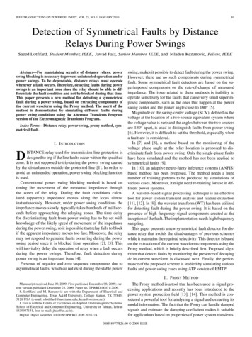
86IEEE TRANSACTIONS ON POWER DELIVERY, VOL. 25, NO. 1, JANUARY 2010TABLE IIICURRENT WAVEFORM COMPONENTS DURING DIFFERENT THREE PHASE FAULTSIn the second case, a three-phase fault that includes arc is considered. Arc has been modeled according to [25]. The dynamicarc characteristics are simulated by the following equation:(13)where is the time varying arc conductance, andconstant, which is calculated as follows:is the time(14)where the coefficient is aboutand is peak valueof arc current, and is the arc length. is the stationary primaryarc conductance calculated as follows:(15)absolute value of arc current;constant voltage parameter per unit length ofprimary arc, which is about 15 V/cm over the rangeof current 1.4 kA to 24 kA.Fig. 11 shows currents due to three-phase fault while arc withlength of 4.5 m is included and happens at 1.0084 s. Amplitudeof decaying dc versus time of phase b has been shown in Fig. 12.Current waveform components during one window data havebeen given in Table II.In this case three-phase fault is detected after 5.6 ms (0.34cycle) and relay is unblocked.Table III shows the current waveform components of differentfault cases at different locations, inceptions, impedance values(Zf), and source impedances (Zs).As Tables I–III show, there is a decaying dc during the threephase fault at least in two phases, while it is not so during thepower swing. As mentioned before, sensing decaying dc component of current waveform can be a suitable property for detecting fault during the power swing.As discussed in Section III, the proposed method should notbe used stand alone. In fact the goal of the proposed method issupervising the existing simple fault detection methods whichwork properly in asymmetrical faults but fail to work in symmetrical faults. For instance negative sequence component-basedmethods explained in Section I are powerful, simple and widelyused methods in power system relaying. However, they fail tooperate in the case of occurrence of symmetrical faults. The proposed method can be added to supervise them in the case ofsymmetrical faults.The fact that the proposed method is based on detectingpresence of decaying dc in current waveform, not calculatingexact amount, makes it able to detect symmetrical fault frompower swing very fast. If the proposed method was based oncalculating exact amount of decaying dc, (for instance therewas a predefined value that should have reached) it wouldimpose extra delay to the algorithm. The proposed method isbased on relative presence of decaying dc in current waveformwhich makes it possible to detect symmetrical faults in fractionof a cycle as demonstrated in simulation results. Therefore itoperates properly even in the fault cases with fast decaying dccomponents.V. CONCLUSIONThis paper introduced a new method for detecting three-phasefault during the power swing, which may be used for unblockingthe distance relay. This method is based on the presence of decaying dc component in the current waveform as a sign of thefault occurrence. The use of this method improves distance relay
LOTFIFARD et al.: DETECTION OF SYMMETRICAL FAULTSdependability by unblocking it during power swing if a fault occurs at the same time.The merit of the proposed method was demonstrated by simulating various cases including solid faults and arc fault on atypical power system. The ease of implementation as well asaccuracy and high speed of fault detection are important advantages of the proposed method.REFERENCES[1] N. Zhang and M. Kezunovic, “A study of synchronized sampling basedfault location algorithm performance under power swing and out-ofstep conditions,” in Proc. PowerTech, St. Petersburg, Russia, Jun. 2005,pp. 1–7.[2] P. J. Moore and A. T. Johns, “New method of power swing blockingfor digital distance protection,” Proc. Inst. Elect. Eng., Gen., Transm.Distrib., vol. 143, no. 1, pp. 19–26, Jan. 1996.[3] X. Lin, Y. Gao, and P. Liu, “A novel scheme to identify symmetricalfaults occurring during power swings,” IEEE Trans. Power. Del., vol.23, no. 1, pp. 73–78, Jan. 2008.[4] S. Jiao, Z. Bo, W. Liu, and Q. Yang, “New principles to detect faultsduring power swing,” in Proc. Inst. Elect. Eng., Developments in PowerSystem Protectio 7th Int. Conf., Amsterdam, The Netherlands, 2001,pp. 515–518.[5] B. Su, X. Z. Dong, Z. Q. Bo, Y. Z. Sun, B. R. J. Caunce, D. Tholomier,and A. Apostolov, “Fast detector of symmetrical fault during powerswing for distance relay,” in Proc. Power Eng. Soc. General Meeting,San Francisco, CA, Jun. 2005, vol. 2, pp. 1836–841.[6] G. Benmouyal, D. Hou, and D. Tziouvaras, “Zero-setting power-swingblocking protection,” presented at the 31st Annu. Western ProtectiveRelay Conf., Spokane, WA, Oct. 2004.[7] A. Mechraoui and D. W. P. Thomas, “A new blocking principle withphase and earth fault detection during fast power swings for distanceprotection,” IEEE Trans. Power. Del., vol. 10, no. 3, pp. 1242–1248,Jul. 1995.[8] A. Mechraoui and D. W. P. Thomas, “A new principle for high resistance earth fault detection during fast power swings for distance protection,” IEEE Trans. Power. Del., vol. 12, no. 4, pp. 1452–1457, Oct.1997.[9] S. M. Brahma, “Distance relay with out-of-step blocking functionusing wavelet transform,” IEEE Trans. Power. Del., vol. 22, no. 3, pp.1360–1366, Jul. 2007.[10] H. K. Zadeh and Z. Li, “A novel power swing blocking scheme usingadaptive neuro-fuzzy inference system,” Electric Power Syst. Res., vol.78, pp. 1138–1146, 2008.[11] J. Faiz and S. Lotfi-Fard, “A novel wavelet-based algorithm fordiscrimination of internal faults from magnetizing inrush currents inpower transformers,” IEEE Trans. Power. Del., vol. 21, no. 4, pp.1989–1996, Oct. 2006.[12] N. Zhang and M. Kezunovic, “Transmission line boundary protectionusing wavelet transform and neural network,” IEEE Trans. Power. Del.,vol. 22, no. 2, pp. 859–869, Apr. 2007.[13] J. Faiz, S. Lotfi-fard, and S. Haidarian Shahri, “Prony-based optimalbayes fault classification of over-current protection,” IEEE Trans.Power. Del., vol. 22, no. 3, pp. 1326–1334, Jul. 2007.[14] M. M. Tawfik and M. M. Morcos, “On the use of Prony method to locatefault in loop system by utilizing modal parameters of fault current,”IEEE Trans. Power Del., vol. 20, no. 1, pp. 532–534, Jan. 2005.[15] M. M. Tawfik and M. M. Morcos, “ANN-based techniques for estimating fault location on transmission line using Prony method,” IEEETrans. Power Del., vol. 16, no. 2, pp. 219–224, Apr. 2001.[16] T. Lobos, J. Rezmer, and H. J. Koglin, “Analysis of power system transients using wavelet and Prony method,” presented at the IEEE PowerTech Conf., Porto, Portugal, Sep. 2001.[17] A. T. Johns and S. K. Salman, Digital Protection for Power Systems.London, U.K.: Peregrinus, 1995.[18] H. M. Tran and H. Akyea, “Numerical Distance Protection Relay Commissioning and Testing,” M.Sc thesis, Chalmers Univ. Technol. Goteborg, Goteborg, Sweden, Oct. 2005.[19] X. Luo and M. Kezunovic, “A novel digital relay model based onSIMULINK and its validation based on expert system,” in Proc.Transmission and Distribution Conf. Exhibit.: Asia and Pacific, 2005,pp. 1–6.87[20] Q. Q. Xu, J. Suonan, and Y. Z. Ge, “Real-time measurement of meanfrequency in two-machine system during power swings,” IEEE Trans.Power. Del., vol. 19, no. 3, pp. 1018–1023, Jul. 2004.[21] L. V. Der Siuis, Transients in Power Systems. New York: Wiley,2001.[22] K. Malmedal and P. K. Sen, “Arcing faults and their effect on the settings of ground fault relays in solidly grounded low voltage systems,”presented at the North American Power Symp., Cleveland, OH, Oct.1998.[23] A. Gaudreau and B. Koch, “Evaluation of LV and MV arc parameters,”IEEE Trans. Power. Del., vol. 23, no. 1, pp. 487–492, Jan. 2008.[24] V. Balamourougan and T. S. Sidhu, “A new filtering technique to eliminate decaying DC and harmonics for power system phasor estimation,”in Proc. Power India Conf., India, Apr. 2006, pp. 1–5.[25] A. T. Johns, R. K. Aggarwal, and Y. H. Song, “Improved techniquesfor modeling fault arcs on faulted EHV transmission systems,” Proc.Inst. Elect. Eng., Gen., Transm. Distrib., vol. 141, no. 2, pp. 148–154,Mar. 1994.Saeed Lotfifard (S’08) was born in Karaj, Iran,in 1982. He received the B.Sc. and M.Sc. degreesin electrical engineering in 2004 and 2006, respectively, and is currently pursuing the Ph.D. degree inelectrical and computer engineering at Texas A&MUniversity.His research interests are power system protection,power-quality analysis, signal processing, and itsapplication to transients and protection of powersystems.Jawad Faiz (M’90–SM’93) received the Bachelorand Master’s (Hons.) degrees in electrical engineering from the University of Tabriz, Tabriz, Iran,in 1974 and 1975, respectively, and the Ph.D. degreein electrical engineering from the University ofNewcastle-upon-Tyne, Newcastle-upon-Tyne, U.K.,in 1988.Early in his career, he was a faculty member withthe University of Tabriz for ten years. After he received the Ph.D. degree, he rejoined the Universityof Tabriz. Since 1999, he has been a Professor at theSchool of Electrical and Computer Engineering, Faculty of Engineering, University of Tehran, Tehran, Iran. His teaching and research interests are switchedreluctance and VR motors design, design and modeling of electrical machines,drives, and transformers.Dr. Faiz is a member of the Iran Academy of Science.Mladen Kezunovic (S’77–M’80–SM’85–F’99) received the Dipl.Ing. degree from the University ofSarajevo in 1974, and the M.S. and Ph.D. degrees inelectrical engineering from the University of Kansasin 1977 and 1980, respectively.Currently, he is the Eugene E. Webb Professorand Site Director of the Power Engineering ResearchCenter (PSerc), an NSF I/UCRC.at Texas A&MUniversity, College Station. He was with Westinghouse Electric Corp., Pittsburgh, PA, from 1979 to1980 and the Energoinvest Co., Europe, from 1980to 1986. He spent a sabbatical at EdF, Clamart, France, from 1999 to 2000. Hewas also a Visiting Professor at Washington State University, Pullman, from1986 to 1987 and The University of Hong Kong in 2007. His main researchinterests are digital simulators and simulation methods for relay testing as wellas the application of intelligent methods to power system monitoring, control,and protection.Dr. Kezunovic is a member of CIGRE and a Registered Professional Engineerin Texas.
IEEE TRANSACTIONS ON POWER DELIVERY, VOL. 25, NO. 1, JANUARY 2010 81 Detection of Symmetrical Faults by Distance Relays During Power Swings Saeed Lotfifard, Student Member, IEEE, Jawad Faiz, Senior Member, IEEE, and Mladen Kezunovic, Fellow, IEEE Abstra