Transcription
Generator Basics
Basic Power Generation Generator Arrangement Main Components Circuit– Generator with a PMG– Generator without a PMG– Brush type– AREP PMG Rotor Exciter Stator Exciter Rotor Main Rotor Main Stator Laminations VPI
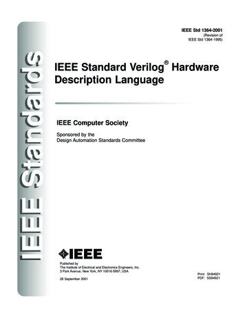
Generator Arrangement Most modern, larger generators have a stationaryarmature (stator) with a rotating current-carryingconductor (rotor or revolving field).Revolvingfield coilsArmaturecoils
Main Electrical Components: Cutaway
Main Electrical Components: Diagram
Circuit: Generator with a PMG As the PMG rotor rotates, it produces AC voltage in the PMG stator. The regulator rectifies this voltage and applies DC to the exciterstator. A three-phase ACvoltage appears at theexciter rotor and is inturn rectified by therotating rectifiers. The DC voltageappears in the mainrevolving field andinduces a higher ACvoltage in the mainstator. This voltage is sensed bythe regulator, compared toa reference level, andoutput voltage is adjustedaccordingly.
Circuit: Generator without a PMG As the revolving field rotates, residual magnetism in it produces asmall ac voltage in the main stator. The regulator rectifies this voltage and applies dc to the exciterstator. A three-phase AC voltageappears at the exciterrotor and is in turnrectified by the rotatingrectifiers. The magnetic field fromthe rotor induces a highervoltage in the main stator. This voltage is sensed bythe regulator, compared toa reference level, andoutput voltage is adjustedaccordingly.
Circuit: Brush Type (Static) DC voltage is feddirectly to the mainrevolving field throughslip rings. Power source for themain revolving fieldcan be very large andexpensive. Requires brushmaintenance. Common in variablespeed applications.ExternalSource( )Stator (armature)(-)Rotor (field)Slip ringsAC out
Circuit: AREP Auxiliary windingregulation excitationprinciple. Secondary winding inthe main statorprovides power to thevoltage regulator.
PMG Rotor Is a field that induces voltagein the PMG stator. Poles are permanent magnets. Mounted on the shaft with themain rotor. Optional (benefits to bediscussed later).
PMG Stator Is an armature that provides powerto the regulator Induced by the PMG rotor. Typically has random-wound coilsin a laminated steel core. Various configurations:– Wound cores in a frame– Wound cores with no frame– Combined with the exciter stator inone frame Mounted on an end bracket(opposite side of prime mover). Optional
Exciter Stator Is a field that induces voltage inthe exciter rotor. Typically powered by the regulator. Typically has random-wound coilsin a laminated steel core. Various configurations:– Wound cores in a frame– Wound cores with no frame– Combined with the PMG in oneframe Mounted on an end bracket(opposite side of prime mover).
Exciter Rotor Is an armature that providesrectified power to the mainrotor (revolving field). Induced by the exciter stator. Three-phase high frequencyAC output. Typically has random-woundcoils in a laminated core. Mounted on the shaft with themain rotor.
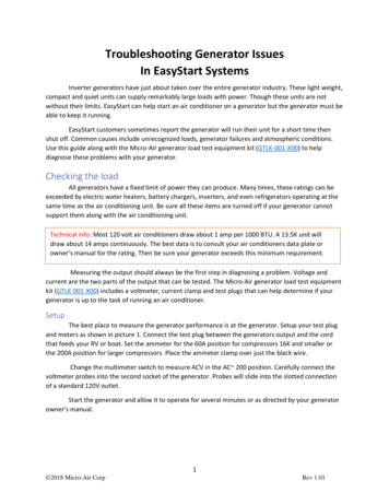
Rectifier Mounted on the exciter (as inprevious slide) or PMG. Has diodes that full wave rectifythe three-phase (three separatevoltage) exciter armature ACcurrent to DC before it entersthe main rotor. Leads connect to the main field(rotor)Resultant DC waveRectifierMain fieldExciterarmature
Main Rotor Is a field that induces voltagein the main stator. Powered by the exciter rotor. Connected to the ( ) and (-)rotating rectifier terminals. Coils are connected in seriesaround a core.– Laminated core is typical– Solid core with large rotors Current flow is directed in aclockwise and CCW rotation to create north and south poles. Pressed on a shaft.NSNTo the rotatingrectifier assemblyS-
Main Rotor: Types Cylindrical Salient
Main Rotor: LayoutMain rotor (field)Exciter rotor(armature)RectifierSelf excitedMain rotor (field)PMGrotor(field)Exciter rotor(armature)RectifierPMG excited
Main Rotor: Frequency, RPM, Pole #Frequency RPM number of poles120If you have a prime mover that runs at 1000RPM and you wanted 50 Hz, you would need agenerator with how many poles?50 Hz 1201000 RPM 6 poles
Main Rotor: Frequency, RPM, Pole ## 5010720601060050
Main Rotor: Damper Cage Also called “Amortisseur windings.” Copper bars through the pole facesand shorted together by the endplates. Standard for all but tractiongenerators, solid rotors. Has a very short time constant(effect expressed in datasheets asX”d).– Helps with parallel operation– Helps with load-induced harmonics(non-linear loads). Helps reduce initial voltage dipduring motor starting.
Main Rotor: Magnetism Magnetic flux paths (i.e. flow of magnetism) for agenerator operating at 0.8 PF
Main Stator Is the main armature,the component thatdelivers power. Windings (copperconductors) are eitherform-wound coils orrandom-wound coilsfitted in core slots. Core is laminatedsteel housed in ametal frame. Typically has threephases (threeseparate windings).
Main Stator: Coils and Slots The number of turns and cross section are specific toeach frame size, slot combination or design, and voltage. Coils typically span into two slots in the core, so there aretwo coils per slot. Pitch (span -1) the number of rotor poles / total # ofslots.
Main Stator: Coil TypesForm woundRandom wound
Main Stator: Coil TypesRandom woundAdvantages, disadvantages, applicationsdiscussed later.Form wound
Main Stator: High-Voltage Coil Use with voltages above 6000 V Has conductive and semi-conductive tape
Main Stator: Coil Connection Series circuit - coilsconnected one afteranother.– Voltage additive foreach coil.– Current capacity is thatof any one coil Parallel circuit - coilsconnected in parallel– Voltage across group isvoltage across any onecoil.– Current capacity isadditive for each coil.
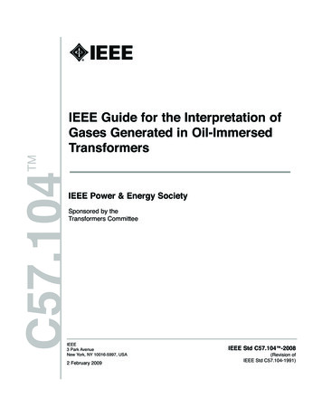
Main Stator: Three Phase Three windings. For each phase, thereis one group (one ormore coils) for eachrotor pole.– A group isinterconnected– Can be considered asone large coil. The leads are typicallywye (star) connected.The neutral is usuallyconnected to ground orbrought out with singlephase loads.2 poles6 groups2 coils/group(12 coils)series connected
Main Stator: Three Phase (cont.) As the rotorrotates, threeseparatevoltages arecreated at thestatorterminals.
Main Stator: Three Phase (cont.)NS4 poles12 groups4 coils/group(48 coils)SN1-9 span2/3 pitch
Wye vs. Delta
Dilbert’s Renewable Energy Idea .
Other Considerations: Laminations Magnetic cores(stacks) used inmanufacturinggenerators aretypically madefrom thin steelsheets calledlaminations. Reduce lossesdue to straycurrents.
Other Considerations: VPI Vacuum pressureimpregnation A polyester or epoxyresin is applied towindings. Provides mechanicalstrength, heattransfer, dielectricstrength andenvironmentalprotection. A bake cycle afterVPI hardens theresin.
Sep 27, 2016 · 4 1800 60 4 1500 50 6 1200 60 6 1000 50 8 900 60 8 750 50 10 720 60 10 600 50. Main Rotor: Damper Cage Also called “Amortisseur windings.” . Generator Basics IEEE