Transcription
,.TRAINING HANDBOOK 9503.1, 9503.2Autolite Model 4300CARBURETOROperation, AdjustmentEJD and OverhaulSERVICETRAININGVOL. 67 52 L2OfficialLicensedProductlicense #2013226
Copyright 2014, Forel Publishing Company, LLC, Woodbridge, VirginiaAll Rights Reserved. No part of this book may be used or reproduced in any manner whatsoeverwithout written permission of Forel Publishing Company, LLC. For information write to ForelPublishing Company, LLC, 3999 Peregrine Ridge Ct., Woodbridge, VA 22192Autolite Model 4300 Carburetor - Operation, Adjustment and OverhaulTraining Handbook 9503.1, 9503.2; Vol. 67 S2 L2EAN: 978-1-60371-212-5ISBN: 1-60371-212-7Forel Publishing Company, LLC3999 Peregrine Ridge Ct.Woodbridge, VA 22192Email address: sales@ForelPublishing.comWebsite: http://www.ForelPublishing.comThis publication contains material that is reproduced and distributed under a license from FordMotor Company. No further reproduction or distribution of the Ford Motor Company material isallowed without the express written permission of Ford Motor Company.Note from the PublisherThis product was created from the original Ford Motor Company’s publication. Every effort hasbeen made to use the original scanned images, however, due to the condition of the material;some pages have been modified to remove imperfections.DisclaimerAlthough every effort was made to ensure the accuracy of this book, no representations orwarranties of any kind are made concerning the accuracy, completeness or suitability of theinformation, either expressed or implied. As a result, the information contained within this bookshould be used as general information only. The author and Forel Publishing Company, LLCshall have neither liability nor responsibility to any person or entity with respect to any loss ordamage caused, or alleged to be caused, directly or indirectly by the information contained inthis book. Further, the publisher and author are not engaged in rendering legal or otherprofessional services. If legal, mechanical, electrical, or other expert assistance is required, theservices of a competent professional should be sought.
AUTOLITE MODEL 4300 CARBURETOROperation, Adjustment and OverhaulTRAINING HANDBOOK 9503.L 9503.2 VOL. 67 S2 L2TABLE OF CONTENTSpageINTRODUCTION.11Design Characteristics . . . . . . . . . . . . . . . . . . . . . . . . . . . . . . . . . . . . . . . . . . . . . . . . . .Carburetor Systen1s . . . . . . . . . . . . . . . . . . . . . . . . . . . . . . . . . . . . . . . . . . . . . . . . . . . . .Construction . , . . . . . . . . . . . . . . . . . . . . . . . . . . . . . . . . . . . . . . . . . . . .11OPERATION.223456778Fuel Inlet Systen1 . . . . . . . . . . . . . . . . . . . . . . . . . . . . . . . . . . . . . . . . . . . . . . . . . . . . . .Idle Fuel Supply System . . . . . . . . . . . . . . . . . . . . . . . . . . . . . . . . . . . . . . . . . . . . . . . . .Primary Main Fuel Metering Systems . . . . . . . . . . . . . . . . . . . . . . . . . . . . . . . . . . . . .Accelerating Pump System . . . . . . . . . . . . . . . . . . . . . . . . . . . . . . . . . . . . . . . . . . . . . .Power Fuel Supply System . . . . . . . . . . . . . . . . . . . . . . . . . . . . . . . . . . . . . . . . . . . . . . .Secondary Main Fuel Metering System . . . . . . . . . . . . . . . . . . . . . . . . . . . . . . . . . . . . .Hot Idle Compensator . . . . . . . . . . . . . . . . . . . . . . . . . . . . . . . . . . . . . . . . . . . . . . . . . . .Automatic Choke System . . . . . . . . . . . . . . . . . . . . . . . . . . . . . . . . . . . . . . . . . . . . . . . .DIAGNOSIS . . . . . . . . . . . . . . . . . . . . . . . . . . . . . . . . . . . . . . . . . . . . . . . . . . . . . . . . . . . . . . . 9Hard, Slow or No Start . . . . . . . . . . . . . . . . . . . . . . . . . . . . . . . . . . . . . . . . . . . . . . . . . . 9Poor Idle . . . . . . . . . . . . . . . . . . . . . . . . . . . . . . . . . . . . . . . . . . . . . . . . . . . . . . . . . . . . . . 9Poor Acceleration . . . . . . . . . . . . . . . . . . . . . . . . . . . . . . . . . . . . . . . . . . . . . . . . . . . . . . . 9Flooding . . . . . . . . . . . . . . . . . . . . . . . . . . . . . . . . . . . . . . . . . . . . . . . . . . . . . . . . . . . . . . 9Running Rich . . . . . . . . . . . . . . . . . . . . . . . . . . . . . . . . . . . . . . . . . . . . . . . . . . . . . . . . . . 10Running Lean . . . . . . . . . . . . . . . . . . . . . . . . . . . . . . . . . . . . . . . . . . . . . . . . . . . . . . . . . . 10Diagnosis Guide . . . . . . . . . . . . . . . . . . . . . . . . . . . . . . . . . . . . . . . . . . . . . . . . . . . . . . . . 10ADJUSTMENT . 12Float Adjustment .Choke Plate Pullclown . . . . . . . . . . . . . . . . . . . . . . . . . . . . . . . . . . . . . . . . . . . . . . . . . . .Fast Idle Cam Choke Clearance . . . . . . . . . . . . . . . . . . . . . . . . . . . . . . . . . . . . . . . . . . .Unloader Clearance (Dechoke) .Air Valve Spring Adjustment .Accelerating Pump Stroke . . . . . . . . . . . . . . . . . . . . . . . . . . . . . . . . . . . . . . . . . . . . . . .Fuel Bowl Vent Valve Adjustment . . . . . . . . . . . . . . . . . . . . . . . . . . . . . . . . . . . . . . . .Choke Setting . . . . . . . . . . . . . . . . . . . . . . . . . . . . . . . . . . . . . . . . . . . . . . . . . . . . . . . . . .Idle Adjustments . . . . . . . . . . . . . . . . . . . . . . . . . . . . . . . . . . . . . . . . . . . . . . . . . . . . . . .131414151515161616OVERHAUL . 17Disassembly . 18Cleaning and Inspection . . . . . . . . . . . . . . . . . . . . . . . . . . . . . . . . . . . . . . . . . . . . . . . . . 19Assembly . . . . . . . . . . . . . . . . . . . . . . . . . . . . . . . . . . . . . . . . . . . . . . . . . . . . . . . . . . . . . 19DEFINITIONS. . . . . . . . . . . . . . . . . . . . . . . . . . . . . . . . . . . . . . . . . . . . . . . . . . . . . . . . . . . . . . 22NATIONAL SERVICE ACTIVITYThe descriptions, testing procedures, and specifications in this handbookwere in effect at the time the handbook was approved for printing. The FordMotor Company reaervee the right to discontinue models at any time, or changespecifications, deeign, or testing procedures without notice and without incurringobligations.FORD DIVISION9'MWFIRST PRINTING- OCTOBER, 1966@ 1966 FORD MOTOR COMPANYDEARBORN, MICHIGAN
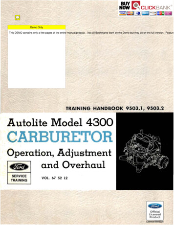
AIR HORNCHOKE PLATEPRIMARY VENTURISHOT IDLECOMPENSATORBODYSECONDARY VENTURISTHROTTLE BODYFig. I - Autoli te Model 4300 CarburetorSECONDARY THROTTLE LOCKOUT
The Autolite Model 4300 (Fig. 1) is a fou rventuri (barrel) carburetor that operates in t wostages. The two primary barrels provide fuel-airmixt ures for most operating conditions. Two secondary venturis are timed to furnish additional fuelair mixtures when the primary throttles are threequarters open.DESIGN CHARACTERISTICSThis carburetor design was adopted with th e follow ing objectives in mind : Adaptability to quality product ion. Acceptable hot fuel ha ndling, hot restar ts, andidle stability. Improved cornering performance. Reduced effect of dirty air cleaners on fueleconomy. Compatibility with exhaust emission controlsystems. Improved choke operation.Mounting a nd air cleaner Aange dimensions a rethe same as on previous F ord four-venturi carburetors. When the Model 4300 is mounted on ex istingfour-venturi intake ma nifolds, t he throttle bores willbe on the same centers .CARBURETOR SYSTEMSA single fuel inlet system serves both th e prim ar yand secondary venturis. T he system has on e bowlCLEAN A IR CLEANERand a dual-pont oon fl oat to cont rol t he fu el levelthrough a conven tional inlet valve (needle-and-seat) .An a uxilia ry inl et valve also is provided to assistfi lling th e bowl when t he carburet or is ha ndling hotvapors and for max imum engine demands.Each of the t wo primary barrels has its own idlesystem and main metering system. The acceleratingpump is a piston type, and disch arges fuel into theprimary venturis when t he t hrottle is opened.One valve-t ype power fuel s upply system provides added fu el to t h e ma in vent uris when t he engine operates under a load.Th e automatic choke system ser ves the primar yvent uris only an d prevent s t h e secondaries fro;noperating when t he engine is cold. Exhaust manifold-heated ai1· is directed t o t h e thermosta tic springwhich controls the choke pla t e posit ion. The chokepulldown device is a vacuum-oper ated p ist on in t hechoke housing.Spring-loaded, offset air valves a re incorporatedin the secondary main met ering· sys tems to con trolair and fuel deliver y to the seconda r y ba r rels . Thesecondar y t lwott le p lates a r e lin ked mechanically tothe primary t hrottle linkage through an overtravel spring. The sprin g permits th e primarythrottles to open fully when t he choke linkag e hasthe secondari es "locked out ."A balanced vent system is used; th at is, t he bowlis always ven ted t o the air horn so t hat pressuredrop through the air clean er doesn't upset t h e calibr ation of t he fuel supply systems (Fig. 2) . Anadditiona l vent is provided t o vent t h e bowl to t hea tmosphe1·e at idle 01· ve1·y low-r pm operation . . .when vaporization is likeliest t o occur in the bowl.Another s pecial f eature of th e Model 4300 is ahot idle compensator system. The compensator isthermostatically oper ated to add air t o t he idle mixture when t he ca rburetor inlet t emperature is high.CONSTRUCTIONDIRTY A IR CLEANE RFig. 2- Balanced CarburetorThe carburetor is built in t hree main assembliesthe upper body or air horn ; the main body ; an d thelower t h rottle body.In t he air horn are contain ed the acceleratingpump linkage, the fuel inlet valves and Aoat, t hepower valve piston and spring, t he choke plate, thebooster venturis, t he secondary bar r el a ii· valvesand th e hot idle compensator valve.The ma in body contains the main meter ing jets,th e accelerat ing pump piston, well , discharge valve,th e power valve, fu el passages for the various systems a nd the id le a ir adj ustment screw.Th e throttle body contains the throttle p lates andlinkage, th e id le f uel a dj ustment needles and theautomatic choke assembly.1
HANDBOOK SCOPEIn the sections that follow, we shall discuss theoperation of each of the systems in the 4300 Carburetor, and then go through diagnosis, adjustmentsand overhaul. Basic carburetor principles will notbe covered; that information is in your traininghandbook entitled "How the Fuel System Operates"- Course 9500.1, and can be reviewed if you happen to be "rusty" on carburetor operation. Thishandbook will give you the complete story of theModel 4300 Carburetor, building on your basic fuelsystem knowledge.Definitions of technical terms appear at the endof the book.FLOATOPERATIONThe Model 4300 Carburetor is designed to s upplya calibrat ed fuel-air mixture to a V-8 engine. Innormal operation, each of the primary ventur is supplies all the fuel,air mixture r equired by four cylinders. The idle, main metering, power fuel s upply,accelerating pump and choke systems go into operation automatically to provide the proper richnessor leanness of the mixture for the operating condition.Operation of the fuel metering systems is controlled by the accelerator linkage, throttle positionand engine speed. The choke system, of course, iscontrolled by the throttle position and the temperature of the engine exhaust manifold.While there is interaction b etween the variouscarburetor systems, operation is best understood byconsidering the systems individually. Let us, then,look at the operation of each system, beginning atwhere the fuel enters the carburetor.FUEL INLET SYSTEMCorrect calibration of any carburetor depends onfuel being available at a specific level in the fuelbowl. If the fuel level is low, the metering systemsdeliver lean mixtures; if the level is high, mixturesare rich. The function of the fuel inlet system is toadmit gasoline into the fu el bowl and maintain thespecified level.Figure 3 shows the construction and operation ofthe fuel inlet system. The fuel inlet is constantlycharged with fuel under pressure from the fuelpump. This fuel enters the bowl through the fuelinlet valve, which is permitted to open when thefloat lowers.The float moves up-and-down with the fuel level.When enough fuel has entered to fill the bowl tothe correct level, the float is high enough for thefloat lever to push the inlet valve (needle) against20AIRFUELFig. 3- Fuel Inlet Systemits seat. Flow of the f uel into the bowl then isblocked until some fuel is used and the float lowersagain.Auxiliary Fuel Inlet ValveAn auxiliary fuel inlet valve is built into thissystem to supplement the main or primary fuel inlet valve when engine fuel requirement s are high.The main or primary fuel inlet valve controlssmall fuel flows precisely because of its small areaof opening and relatively high valve-to-seat sealingpressure. When large fuel flows are required, as inh igh engine speeds and heavy-load conditions, thefuel level and float height drOJ?, thereby opening theauxiliary valve (Fig. 4) in addit ion to the mainor primary fu el inlet valve. The total combined fuelvalve opening is larger than the previous single valvethat has been used in former Ford carburetors.In addition to supplying fuel for high engine loadconditions, the large combined valve opening a lsopurges the carburetor-to-fuel pump line, after a hotrestart, of fuel vapor that forms during a hot soakcondition.Venting the BowlTwo stand pipes beside the air horn (Fig. 3)vent t he bowl to the fresh air inlet. The stand pipes
valve provides relief during periods of idle and partt hrottle operation when vapor is likely to form inthe bowl.IDLE FUEL SUPPLY SYSTEMSPECIF IEDFLOATDROPSlWhen the throttles are closed or nearly closed,there is not enough air flow through the venturis tocreate the vacuum needed to operate the primarymain metering system. Therefore, we have a separate fuel metering system for idle operation.The primary idle fuel supply system (Fig. 6) usesthe pressure difference between manifold vacuumand atmospheric pressure in the bowl to cause fuelflow. Idle system fuel flow is from the bowl, t hroughthe main metering jets and into the main wells.From there, the fuel flows up through calibratedrestrictions in the idle t ubes, t hen down the idlechannels to the idle cavities in the throttle body. Itenters the venturis below the throttle plates throughthe idle discharge port and idle transfer slot. Theidle fuel adjustment screw regulates the amount offuel that is discharged through the port.HIGH -SPEEDAIR BLEEDDAIR FUELIDLE AIR BLEEDDAI RIll FUELrnFUEL AND AIRD VACUUMFig. 4- Auxiliary Fuel Valve Operationare open to the carburetor intake air after the airpasses through the air cleaner. Thus, the bowl pressure and air horn pressure are equal during mainmetering system operation, and the calibration ofthe carburetor isn't affected by the air cleaner'scondition.An external vent valve (Fig. 5) is opened by alever actuated by the accelerating pump linkagewhen the throttle is closed, or nearly closed. ThisIDLE FUEL ADJUSTMENT SCREWFig. 6-ldle Fuel Supply SystemAir BleedsFiltered air is mixed with the fuel t hrough t heidle air bleeds to help the fuel atomize as it is discharged. The bleed also prevents siphoning throughthe idle system at very high speeds, or when theengine is shut down.Idle Transle r SlotFig. 5- External Vent ValveThe idle transfer slot in each venturi serves bothas an air bleed and as a secondary discharge port.At closed throttle (Fig. 7), the top of the slot3
admits air into the idle cavity, and the bottom ofthe slot delivers fuel to the vent uri. When t hethrottle opens slightly above an idle condition, thewhole length of the slot becomes a discharge port torichen the mixture (Fig. 7). This secondary discharge opening prevents the increase in air flowfrom making the mixture too lean. There would bea "flat spot" in the transition from t he idle to themain metering system without the transfer slot.provides t he fuel required by the engine at cruisingspeeds. Main metering systems are calibrated to deliver a lean mixture . about 15 parts air to onepart gasoline . . when the engine is loafing along.When more power is required, the main meteringsystem continues t o operate, and the mixture ismade richer by other systems.Parts of the Main Metering SystemIn t he Model 4300 carburet or, t he primary mainmetering system (Fig. 8) has two main meteringjets;. main wells, and main well t ubes; calibrated airbleeds; discharge nozzles; and booster venturis. Atrest, fuel flows from t he bowl, t hrough the mainjets, and into the main wells and tubes. In eachwell and tube, the fuel assumes the same level asin the bowl until the engine begins to operate.Pressure Difference Causes FlowWit h the engine operating, the main meter ingsystem delivers fuel in response t o t he t hrottleplate opening. Opening the t hrottle causes air flowt hr ough the main venturi and booster vent uri ; theflow through t he booster venturi causes a pressuredrop or partial vacuum at the discharge nozzle. Thefuel bowl is at air horn pressure, so we have a pressure difference that creates flow through the system. Fuel is sprayed out the discharge nozzle andmixes with the airstream.PORTDAIR(I] FUELD VACUUMFUEL AND AIRFig. 7-ldle Transfer Slot is SecondaryDischarge PassageDAI R FU EL[I FUELBOOSTER VENTURIAND AIRD VACUUMIdle Air Bypass SystemThe idle air bypass syst em (Fig. 6) is incorporatedin the idle system. This provides a precise way ofadjusting idle rpm by admitting more or less airto the mixture after it is discha1·ged into the barrel.Filtered air enters this syst em through a pick-uphole near the base of the main venturi. The airpasses the idle air adjustment scr ew down into thethrott le body; then, is discharged below the t hrottleplat e.Opening the idle air adjustment screw leans themixture and incr eases engine rpm. The idle fueladjustment screws-one for each idle system-permitadding more fuel if needed for a smooth idle.MAIN WELL TUBEPRIMARY MAIN FUELFig. 8- Primary Main Metering SystemMETERING SYSTEMSThe size of the main j et determines how muchfuel is delivered for a given volume of air flow. Increasing or decreasing throttle opening increases orA primary main fuel metering system, dividedinto two parts . one for each primary barrel .4MAINMETERING JET
decreases the fuel delivery so that the mixtur e proportion or ratio is quite constant.DAIR FUE LBleed Assists VaporizationThe high-speed air bleed (Fig. 9) in the systempermits some air to be mixed with the fuel in themain well. The air enters the main well tube throughtwo holes when fuel is flowing in the system. Adding air at this point assists vaporization, and compensates for the tendency of the air to become lessdense at high speeds. The bleed also doubles as ananti-siphoning vent at low speeds. And it discouragespercolation when a hot engine is shut down by venting the main well.PARTIALVACUUMINTAKE CHECK VALVE (UNSEATED)Fig. 10- Accelerating Pump System-IntakeFig. 9- High-Speed Air BleedsACCELERATING PUMP SYSTEMAir, being very light, responds rapidly to changesin the throttle opening. Gasoline is heavier, andtherefore not as responsive. When the throttles areopened suddenly, air flow increases rapidly, but fuelflow lags. So that the engine will respond instantlyto opening the throttle, we have an acceleratingpump system, which furnishes a single spur t offuel in each primary venturi when the throttles areopened.Piston-Type PumpA piston-type pump (Fig. 10) is actuated by a linkfrom the accelerator linkage and by a spring tocause the pumping action. The pumping chamber isformed below a cup on the pump piston. A ball-typeintake check valve and a needle-type discharge valvecontrol the flow of fuel into and out of the pumpingchamber and channels. Discharge nozzles open intoboth primary venturis.Fuel IntakeFuel intake occurs as the throttles are closed (Fig.10). The accelerating pump link pulls the piston up,compressing the piston spring. A partial vacuumor void is created below the piston cup in the pumping chamber.Fuel in the bowl, at this time, is exposed to fullatmospheric pressur e, as the external vent valvelever also is actuated by the accelerating pump linkto open the valve.The pressure difference pushes the intake checkvalve off its seat and causes fuel to flow from thebowl into the pumping chamber. The discharge valveis seated, and prevents backftow in the dischargepassages.Fuel DischargeWhen the throttles open (Fig. 11), the end of theaccelerating pump link moves down in the piston armslot, and the spring pushes the piston into the pumping chamber. Pressure builds up in the chamber toforce the inlet valve closed on its seat.Fuel is pumped through the discharge passages. the discharge valve is forced open by the fuelpressure . and fuel is sprayed out the dischargenozzle. When the piston has reached its limit oftravel (depending on how far the accelerator is depressed), flow stops and the discharge valve seats.The discharge passages remain primed, or full offuel, so that pumping action t hrough the nozzles isinstantaneous on the next cycle.Air Bleed Check ValveWith the engine operating at high speed, avacuum exists at the accelerating pump discharge5
.FUELVACUUM PISTONSPR INGSPOWER VALVEOUT LETCHAN N EL FUELOvACUUMCLOSEDPOW ER JETFig. 11-Accelerating Pump - Discha r geFig. 12-Power Fuel Supply Systemn ozzles. An a ir bleed check valve prevents thisvacuum from siph oning fuel through the accelerating pump system when fuel is not being dischar ged.The valve is placed at the upper end of the disch argenozzle passage.Another Passage to the Main WellPOWER FUEL SUPPLY SYSTEMWe have said t hat t he main metering system provides a lean mixture for cruising con ditions, whenpower requir ements are not h igh. When more poweris required . . for high-s peed operation or for accelerating . . we have to burn more fuel. T he smallamount of fuel in a lean mixture doesn't provideenough heat upon combustion for full engine power .Therefore, we provide a way to "step up" or richenthe mixture . . . we call this " step up" system thepower fuel s upply system (Fig. 12).Vacuum Piston and Power ValveThe power fuel s upply system uses a vacuumcontrolled pist on in t h e air h orn body and a powervalve to admit more fuel when power is required.The vacuum piston rod is spring-loaded and tendsto push t h e rod down . Th e stem of t he power valvealso is spring-loaded, tending to hold the powervalve up or closed .Manifold vacuum is sensed on top of the pistont hrough passages in the carburetor bodies. At idleor cruising con ditions, the vacuum is high enough toovercome the piston rod spring force. The piston androd are held up and away from the power valve stern.The power valve spring then holds the valve closed.6When the engine is under load, the vacuum dr ops.The vacuum piston r od is pushed down by its s pringand t he rod pushes on t h e power valve stem. Thecomparatively light power valve spring is overcome,and the valve opens (Fig. 13). Opening t he valvegives us another passage from the bowl to t he mainwells . . . th rough th e valve and power jets. Theeffect is the same as if we temporarily increasedMAIN WELLDAIRII FUELD VACUUMVALVE OPENSFig. 13- Power Valve Action
9 503.1 and 2-1DESCRIPTIONThe Ford 4300 model carburetor is a four-venturi type. It has three main assemblies; the air horn,the main body and the throttle body.The main sub - assemblies contained in the air horn casting are: the accelerating pump piston, returnspring and operating link; the fuel inlet needle, seat and float; the secondary air throttle plates and torsionspring; the choke plate; the hot idle compensator valve; the linkage and piston for the secondary airthrottle damper, the primary and secondary booster venturis and the vacuum piston and spring for thepower valve.Under the air horn assembly is the main body. It contains the main metering jets, the power valve,the idle system air adjusting screw, the accelerating pump discharge needle, and fuel passages for thevarious systems.Beneath the main body is the throttle body. Contained in the throttle body are the primary and secondary throttle plate.s and linkage, the idle fuel adjusting needles, and the automatic choke housing, bimetal spring and pulldown piston.This carburetor design was adopted with the following objectives in mind: Adaptibility to quality production. Acceptable hot fuel handling, hot restarts, and idle stability. Improved cornering performance. Reduced effect of dirty air cleaners on fuel economy. Compatibility with exhaust emission control systems. Improved choke operation.The 4300 model carburetor will mount on the existing four-venturi intake manifolds with the throttlebores being on the same centers as previous Ford four-venturi carburetors.Mounting height and air cleaner flange diameter has been maintained the same as on past models.
'--FORD 4300 CARBURETOR SERVICE TRAIN ING9503.l and 2 -1
9503.l and 2-2OPERATIONFUEL INLET SYSTEMFuel enters the carburetor through the fuel inlet channel located in the air h orn. A needle v alve andseat regulates the quantity of fuel flowing into the fuel bowl located in the main body. The quantity of fuelis regulated by the ·distance the needle valve is moved off the seat and by fuel pump delivery (volume andpressure). Correct fuel pump delivery is necessary if the specified fuel level within the carburetor is to bemaintained.The fuel level withi n the carburetor is maintained at a predetermined level by a dual pontoon floatand lever assembly, which controls the movement of the needle valve. The float reacts to any lowering inthe fuel level. The needle riding on the float lever falls away from the seat as the float drops to a lower fuellev el.To prevent fuel starvation during hot fuel vapor handling, an auxiliary fuel inlet valve opens to supplement the main fuel inlet valve. The auxiliary valve opens when the float drop s below a predeterminedlevel. The float lever presses against the a uxiliary valve plunger, opening the valve for additional fuel toenter the fuel bowl.The fuel bowl is vented internally by two stand pipes located adjacent to the choke air horn. In addition, a mechanically actuated valve vents the fuel bowl externally during periods of idle and part throttleoperation, when fuel vapor is most likely to form. The accelerator pump link contr ols the movement ofthe external vent valve.
INTERNAL BOWL VENT-----iAUXILIARYVALVE AND SEATFUEL INLET VALY.E AND SEATCJ AIRCJ FUELFUEL INLET SYSTEM SERVICE TRAINING9503.l and 2- 2
9503.1 and 2-3OPERATION -ContinuedIDLE SYSTEMIdle FuelThe primary idle fuel system functions when the engine is operating at low engine rpm. It supplies thefuel- air mixture when the air flow past the carburetor venturi is insufficient to operate the main meteringsystem. Air bleeds, restrictors and adjustments are provided to control and meter the idle fuel - air mixture.At curb idle speeds, the throttle plates are completely closed and with manifold vacuum below theplates, enough difference in pressure is created between the fuel bowl and the idle dischar ge por ts to operate the idle fuel system.Fuel is forced from the fuel bowl through the main metering jets and into the main well. The fuel thenflows up through a calibrated restriction in the idle tube. Filtered air enters an idle air bleed restrictionand mixes with the fuel flowing up the idle tube. The idle air bleed also serves as an anti- syphoning ventat high engine speeds or when the engine is shut down. The fuel - air mixture passes down the idle channelinto an idle cavity in the throttle body. The idle cavity has an upper and lower discharge port. At curbidle (throttle plate closed), the idle fuel- air mixture flows past an idle fuel adjusting screw and is dis charged b elow the throttle plate from the lower disch arge port an d from a small portion of the upp erdischarge port.The upper discharge port is a vertical slot- type port and extends slig htly b elow the closed throttleplate. When opening the throttle plate, a greater portion of the upp er discharge port is exposed to m ani fold vacuum and a larger amount of idle fuel- air mixture will discharge from the upper port. Furtheropening of the throttle plate results in a decrease in manifold vacuum and a decrease in the quantity ofidle fuel- air mixture that is discharged. As the idle system tapers off, the main fuel metering system beginsto discharge fuel.Idle Air BypassThe idle sp eed (engine rpm) is adjusted by turning an idle air adjusting screw to admit m ore or lessair, as required, below the throttle plates. This method of a ir control bypasses the throttle plates. Filteredair enters through a pickup hole located near the base of the main venturi. The air passes by th e idle airadjusting screw and down into the throttle body. The air is then discharged from a port below the throttleplate.It is particularly important that the idle air and the idle fuel mixture adjustments are performed at thesame time. Opening the idle air screw to increase engine rpm leans the fuel- aix mixture, consequently, theidle fuel mixture must also b e increased to provide the proper fuel - air mixture for smooth engine idle.
TRAINING HANDBOOK 9503.1, 9503.2 Autolite Model 4300 CARBURETOR Operation, Adjustment EJD and Overhaul SERVICE . Forel Publishing Company, LLC, Woodbridge, Virginia . valve opening