Transcription
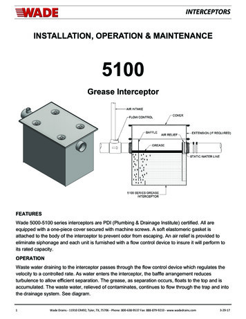
INTERCEPTORSINSTALLATION, OPERATION & MAINTENANCE5100Grease InterceptorFEATURESWade 5000-5100 series interceptors are PDI (Plumbing & Drainage Institute) certified. All areequipped with a one-piece cover secured with machine screws. A soft elastomeric gasket isattached to the body of the interceptor to prevent odor from escaping. An air relief is provided toeliminate siphonage and each unit is furnished with a flow control device to insure it will perform toits rated capacity.OPERATIONWaste water draining to the interceptor passes through the flow control device which regulates thevelocity to a controlled rate. As water enters the interceptor, the baffle arrangement reducesturbulence to allow efficient separation. The grease, as separation occurs, floats to the top and isaccumulated. The waste water, relieved of contaminates, continues to flow through the trap and intothe drainage system. See diagram.1Wade Drains ‐ 11910 CR492, Tyler, TX, 75706 ‐ Phone: 800‐638‐9537 Fax: 888‐879‐9233 ‐ www.wadedrains.com3‐29‐17
INTERCEPTORS5100 Grease InterceptorRegularly Furnished: Fabricated A.R.C. steel grease interceptor with removable baffles, gasketed cover, & external flow control fi ng.Flow imensions (Inches)ABCDEFWt.Lbs.H484.410 1/2181310.25715 1/43 1/240.07145.412 1/818 3/161310 1/48 5/815 1/43 1/243.010207.313 1/420 1/814 3/412 3/89 3/417 3/83 1/259.0153011.013 1/4251716 1/49 1/422 1/4471.0204012.613 1/42718 3/4169 3/424 1/43 1/290.0255019.818 1/2262017 1/41423 1/44 1/2108.0129.0357028.622 1/228 3/42017 1/41825 3/44 1/25010037.422 1/2302421 1/41827 1/44 1/2151.07515057.123 3/834 5/830 5/827 7/817 1/231 7/85 7/8156.0100200106.227 5/841 3/835 5/832 7/82238 5/85 5/8172.0Suffix Op onsSize / GPM‐HDHeavy Duty Cover‐24*Anchor Flange‐26*Anchor Flange w/Clamping Device‐FH*Cradle Housing‐FHT*Enclosed Housing‐T*Tile Recess‐XT* ExtensionUp to 6”Each 1” over 6” 2Wade Drains ‐ 11910 CR492, Tyler, TX, 75706 ‐ Phone: 800‐638‐9537 Fax: 888‐879‐9233 ‐ www.wadedrains.com3‐29‐17
INTERCEPTORS5100 Grease Interceptor3Wade Drains ‐ 11910 CR492, Tyler, TX, 75706 ‐ Phone: 800‐638‐9537 Fax: 888‐879‐9233 ‐ www.wadedrains.com3‐29‐17
INTERCEPTORSINSTALLATIONInstall the interceptor as close as practical to the fixture(s) being served. Avoid installations where long runs of pipe(exceeding 25’) are necessary to reach the interceptor. This precaution will preclude the possibility of grease becomingcongealed in the pipe before it reaches the interceptor.The unit may be placed on the floor, partially recessed in the floor, recessed with the top flush with the floor or encasedbelow the floor in an appropriate housing to accommodate piping and structural considerations. Whatever the installationmethod, anticipate sufficient clearance to remove the cover and baffle for cleaning. Verify that no obstructions will beplaced over the interceptor after installation. A minimum clearance equal the overall height of the interceptor (excludingany extension) is recommended.Do not install the grease interceptor in a waste line from a garbage grinder.Garbage grinder waste must bypass the interceptor because the rapid accumulation of solid matter will significantlyreduce the rated efficiency of the interceptor. In an application where solids will be present, a solids interceptor shouldbe used.A separate grease interceptor is recommended for each commercial dishwasher.The size is determined by the discharge rate of the dishwasher as stated by the manufacturer.Placement of a grease interceptor in a high traffic area is an important concern. If the unit is to be installed flush with thefloor, it is necessary to load rate the interceptor cover. The standard Wade interceptor is designed for pedestrian andlight traffic only. If heavy loads are anticipated, the interceptor must be specified with an appropriate reinforced cover. Anextension is frequently used to increase the rough-in dimension from the inlet/outlet centerline to the finished floor. Theextension anchor flange is not adequate to support the entire interceptor. For installations at flush-with-floorlevel, the interceptor chamber must rest on solid ground or a concrete pad. For upper floor installations, (suspendedabove the lower floor ceiling), the interceptor must be independently supported on hangers suitable to carry the entireweight.A single interceptor serving multiple fixtures is recommended only where the fixtures are located close together. In theseinstallations, each fixture should be individually trapped and vented.4Wade Drains ‐ 11910 CR492, Tyler, TX, 75706 ‐ Phone: 800‐638‐9537 Fax: 888‐879‐9233 ‐ www.wadedrains.com3‐29‐17
INTERCEPTORSFLOW CONTROLThe flow control device is designed with an integral orifice to achieve a predetermined optimum flow rate, thuseliminating turbulence and to regulate surges in the drainage line. The orifice opening in the flow control device is relatedto the size and flow rating of the grease interceptor. The standard orifice sizes are for gravity flow conditions where nopressure buildup is anticipated. If an interceptor is operating at maximum flow levels, a pressure head may develop,which may cause an overload condition.Using the supplied flow control device is an important factor in the operation of the grease interceptor. The flow controldevice must be installed in the waste line upstream of the grease interceptor. Typically, the device is placed beyond thelast connection from the fixture(s) and as close as possible to the underside of the lowest fixture. When two or moresinks or fixtures are combined and served by a single interceptor, a single flow control may be used.The supplied flow control device must be properly vented to permit air to mix with the fluid entering the interceptor. Airfacilitates the separation and, more Importantly, is necessary to maintain optimum pressure, thereby maintaining theproper operating level within the interceptor chamber.The flow control air intake may terminate under the sink drain board as high as possible, to prevent overflow. Anothermethod is to terminate the vent outside the building. It is recommended that the installer check with the local plumbingcode authority.VENTINGGrease interceptors must have a vented waste, sized in accordance with code requirements for venting traps, to retain awater seal and to prevent siphoning.FC-IPSFlowRatePipeSizeVentSizeABC42”1 1/4”3 15/16”2 11/16”.50072”1 1/4”3 15/16”2 11/16”.688102”1 1/4”3 15/16”2 11/16”.844152”1 1/4”3 15/16”2 11/16”1.000203”1 1/2”5 5/16”3 11/32”1.156253”1 1/2”5 5/16”3 11/32”1.313354”2”6 11/16”4 11/32”1.500504”2”6 11/16”4 11/32”1.875FC-NH542”1 1/2”5 1/16”2 1/2”.50072”1 1/2”5 1/16”2 1/2”.688102”1 1/2”5 1/16”2 1/2”.844152”1 1/2”5 1/16”2 1/2”1.000203”1 1/2”5 1/16”3 1/4”1.156253”1 1/2”5 1/16”3 1/4”1.313354”1 1/2”5 1/16”3 11/16”1.500504”1 1/2”5 1/16”3 11/16”1.875Wade Drains ‐ 11910 CR492, Tyler, TX, 75706 ‐ Phone: 800‐638‐9537 Fax: 888‐879‐9233 ‐ www.wadedrains.com3‐29‐17
INTERCEPTORSFactors Affecting Grease interceptor PerformanceVelocity of Incoming WaterA higher velocity of water will contribute to turbulence and slow the grease separation process, thereby reducingefficiency. Installation of additional flow control devices at all the sources of flow may be required.Grease to Water RatioHigher ratios of grease particles to the water will the lower the efficiency of the interceptor – If high ratios of water togrease are anticipated, increase the size of the interceptor one or two units.Detergents in the SystemDegreasing agents or grease cutting detergents will break down the liquid grease into minute particles that can causeslower separation time, thus allowing these particles to pass through the interceptor. Increasing the size of theinterceptor will allow longer retention rates and improve the efficiency.Flow CapacityIf maximum recommended flow rates are exceeded, the efficiency of the interceptor will be decreased. Either installadditional flow controls devices at all sources of flow, or install a larger interceptor.Specific Gravity of FiltratesGrease has a lower specific gravity than water and will separate and rise to the surface quickly. If the waste water hasfood particles or solids having a higher specific gravity than water, these filtrates will accumulate at the bottom,eventually passing out of the interceptor. If high concentrates of solids are anticipated, the installation of a solidsinterceptor is recommended.Installation LocationThe interceptor should be located as close as possible to the source of grease. Piping to the interceptor could becomeclogged if the liquid cools prior entering the interceptor.6Wade Drains ‐ 11910 CR492, Tyler, TX, 75706 ‐ Phone: 800‐638‐9537 Fax: 888‐879‐9233 ‐ www.wadedrains.com3‐29‐17
INTERCEPTORSMAINTENANCEGeneral ConsiderationsDesign and installation are key factors in the operation of a grease interceptor; however, without a disciplinedmaintenance program, efficiency and performance can be adversely affected. If adequate maintenance is not performed,excessive grease buildup will occur until the water ladended with grease passes directly through the unit. Regardless ofdesign efficiency or installation, grease interceptors perform only as well as the maintenance schedule allows.Cleaning (5000 and 5100 Series)The frequency of cleaning is determined by the use load factor and the capacity of the installed interceptor. An idealcleaning cycle can be established after the unit has been in operation for several weeks. A logical cleaning schedule isnormally determined by checking the unit after a normal shift, or following a period of peak usage. Grease removalintervals may vary from once a week to once in several weeks. Never clean an interceptor during a time when customersare present, as the offensive odors may develop inside the interceptor. Cleaning can easily be performed by followingthe steps listed:1. Loosen and remove the fasteners securing the cover to the interceptor body.2. Gently pry the cover from the body being careful not to damage the gasket seal.3. With the cover removed, skin the grease from the inside and place in a disposable container. Never dispose ofthe contents in any part of the plumbing system.4. Remove the baffle assembly and sediment basket (if so equipped) and clean.5. Remove accumulated solids from the bottom.6. Replace internal components and secure the cover.7. Periodic inspections of the flow control orifice are suggested.7Wade Drains ‐ 11910 CR492, Tyler, TX, 75706 ‐ Phone: 800‐638‐9537 Fax: 888‐879‐9233 ‐ www.wadedrains.com3‐29‐17
INTERCEPTORSCleaning (5103 Series) Semi-Automatic InterceptorTo assist in the maintenance and cleaning process, Wade offers a unit incorporating a top draw-off port for greaseremoval. The cover has an accumulating hood to capture the liquid grease and funnel into the draw off port. Cleaningcan easily be performed by following the steps listed:1. The interceptor in normal use has the control valve off and the drain port plugged. When cleaning is required, run afull stream of hot water through a fixture serviced by the interceptor. This will liquefy the grease for extraction. Aperiod of two minutes is required.2. With the hot water supply shut off, turn the in-line closure valve to a fully closed position.3. Remove the bronze plug from the cover and insert the hose fitting and flexible draw off hose, tightening the hosefitting securely. Place the end of the hose into a container suitable for disposal.4. Turn the hot water supply back on back on and allow the water pressure to steadily force the liquefied greasethrough the hose. Caution: The liquid grease may be hot when exiting the draw-off hose; take care to keep the waterflow as laminar as possible to prevent grease spilling.5. Once grease is no longer visible at the discharge end, turn the water supply off. Properly dispose of the grease.Never dispose of the contents in any part of the plumbing system.6. Remove the draw-off hose and fitting and replace the bronze plug.7. Fully open the in-line control valve.8. Periodic inspections of the flow control orifice are suggested.9. A bi-annual inspection of the internals of the interceptor is recommended. Inspect and clean the baffle assembly andthourghly clean the body of all solids and debris.8Wade Drains ‐ 11910 CR492, Tyler, TX, 75706 ‐ Phone: 800‐638‐9537 Fax: 888‐879‐9233 ‐ www.wadedrains.com3‐29‐17
INTERCEPTORSEXTENSIONS (Bolt-On & Integral)Extensions should be specified on grease and oilinterceptors when the interceptor is buried in the ground,vertical adjustment of the interceptor is necessary tomeet the drainage piping, and/or floor level accessrequirements. Extension heights range from four inchesto any maximum practical for serviceability. Extensions inexcess of 20" are not recommended. One must considerthe slope of the drainage piping from the fixtures to theinlet of the interceptor. Typically, allow a slope of ¼" perfoot in the drainage pipe. Therefore, there will be manyinstallations, especially with large interceptors, wherethe sloped drainage pipe ends up below the inletconnection. An extension is added to the top of theinterceptor so that the inlet can be lowered to meet theincoming drainage pipe and the lid of the interceptor canbe extended to floor level.Wade offers three different kinds of extensions: integral,bolt on and cover shrouds. An integral extension isspecified by expanding the "H" dimension on theinterceptor. The "H" dimension is from the center of theinlet and outlet to the top of the interceptor. One wouldspecify a "H" dimension to meet the job requirementsand the interceptor will be manufactured to thatspecification. The extension is incorporated into theproduction of the interceptor to produce a seamless,integral interceptor.A second method of providing an extension is a bolt ondesign. In this example, a top is manufactured out of thesame material as the body. The extension is secured tothe body by means of bolts bearing against its baseflange, compressing the sealing gasket to complete theunion. The regular lid is bolted to the extension top in thesame manner as it would be to the body of a standardinterceptor.SHROUDSCover shrouds incorporate either standard or draw-offgrease interceptors mounted on adjustable elevationcradles in either open or closed bottom housings withnon-skid floor level lids. The cover shroud is adjustableand is recessed into the slab to house the interceptor.Cover shrouds are particularly important where belowfloor level installation of draw-off grease interceptors isrequired, because such models cannot be installedindependently with tops at the finished floor level.9Wade Drains ‐ 11910 CR492, Tyler, TX, 75706 ‐ Phone: 800‐638‐9537 Fax: 888‐879‐9233 ‐ www.wadedrains.com3‐29‐17
INTERCEPTORSEXTENSIONS (Adjustable)In installations where the exact extension dimension required is unknown or where little notice has been provided to the installeradvising of the need for an extension; integral and bolt on extensions are impractical due to the time necessary for their fabrication.Wade’s nationwide network of manufacturer's representatives stock adjustable extensions for immediate shipment to jobsites whenthese situations occur. The extension is adjustable and is secured to the interceptor similar to a fixed extension. After bolting theextension to the interceptor, the top is adjustable to grade.Installation NoteIf adjustable extension is install in areas other than on grade where fumes may seep from the adjustable extension connections, anoptional rope seal is recommended. The 1/2” diameter neoprene sponge gasket is installed in the annular space between the upperand lower housings. For the slotted openings, it is recommended that these spaces be sealed with a elastomeric flex seal tape withgood adhesion characteristics. For slab on grade installations where it is desirable to seal the housing from back-fill, an aluminum foilduct tape is suitable.10Wade Drains ‐ 11910 CR492, Tyler, TX, 75706 ‐ Phone: 800‐638‐9537 Fax: 888‐879‐9233 ‐ www.wadedrains.com3‐29‐17
A separate grease interceptor is recommended for each commercial dishwasher. The size is determined by the discharge rate of the dishwasher as stated by the manufacturer. Placement of a grease inte