Transcription
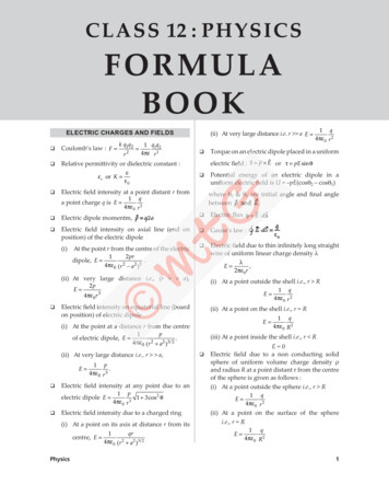
CLASS 12 : PHYSICSFORMULABOOKELECTRIC CHARGES AND FIELDS Coulomb’s law : F k q1q2r2 1 q1q24 πε r 2 Relative permittivity or dielectric constant :i.e., ε r or K εε 0 Electric field intensity at a point distant r froma point charge q is E 1 q.4 πε 0 r 2(ii) At very large distance i.e. r a E Torque on an electric dipole placed in a uniform electric field : τ p E or τ pE sin θ Potential energy of an electric dipole in auniform electric field is U –pE(cosq2 – cosq1)where q1 & q1 are initial angle and final anglebetween Electric dipole momentm, Electric flux φ E dS Electric field intensity on axial line (end on Gauss’s law :position) of the electric dipole(i)At the point r from the centre of the electricdipole, E 2 pr1.4 πε 0 (r 2 a 2 )2(ii) At very large distance i.e., (r a),E 2p Electric field due to thin infinitely long straightwire of uniform linear charge density lE λ,2 πε 0r(i) At a point outside the shell i.e., r R4 πε 0r 3E Electric field intensity on equatorial line (boardon position) of electric dipolep1.4 πε 0 (r 2 a 2 )3 / 2(ii) At very large distance i.e., r a,E 1 p.4 πε 0 r 3 Electric field intensity at any point due to anelectric dipole E 1 p1 3 cos 2 θ4 πε 0 r 3 Electric field intensity due to a charged ring(i) At a point on its axis at distance r from itscentre, E Physicsqr124 πε 0 (r a 2 )3 / 21 q4 πε 0 r 2(ii) At a point on the shell i.e., r RE (i) At the point at a distance r from the centreof electric dipole, E 1 q4 πε 0 r 21 q4 πε 0 R 2(iii) At a point inside the shell i.e., r RE 0 Electric field due to a non conducting solidsphere of uniform volume charge density rand radius R at a point distant r from the centreof the sphere is given as follows :(i) At a point outside the sphere i.e., r RE 1·q4 πε 0 r 2(ii) At a point on the surface of the spherei.e., r RE 1 q·4 πε 0 R 21
(iii) At a point inside the sphere i.e., r RE ρr1 q r ·, for r R3ε 0 4 πε 0 R 3 Electric field due to a thin non conductinginfinite sheet of charge with uniformly chargeσsurface density s is E 2ε0 Electric field between two infinite thin planeparallel sheets of uniform surface chargedensity s and – s is E s/e0.ELECTROSTATIC POTENTIAL ANDCAPACITANCE Electric potential V E Vwhere Electric potential energy of a system of twopoint charges is U R is C 4pe0R Capacitance of an air filled parallel platecapacitorWq Capacitance of an air filled spherical capacitorq4 πε 0r Capacitance of an air filled cylindrical capacitor The electric potential at point due to an electricdipoleV 1 p cos θ4 πε 0 r 2 Electric potential due to a uniformly chargedspherical shell of uniform surface chargedensity s and radius R at a distance r from thecentre the shell is given as follows :(i) At a point outside the shell i.e., r RV 1 q4 πε 0 rV 1 q4 πε 0 R(ii) At a point on the shell i.e., r R(iii) At a point inside the shell i.e., r RV 1q4 πε 0 R Electric potential due to a non-conducting solidsphere of uniform volume charge density r andradius R distant r from the sphere is given asfollows :(i) At a point outside the sphere i.e. r R1 qV 4 πε0 r(ii) At a point on the sphere i.e., r RV 1 q4 πε 0 R(iii) At a point inside the sphere i.e., r RV 21 q1q24 πε 0 r12 Capacitance of a spherical conductor of radiusC 4 πε 0 Electric potential at a point distant r from apoint charge q is V Relationship between E and V1 q( 3R 2 r 2 )4 πε 02R3C abb a2 πε 0 L b ln a Capacitanceof a parallel plate capacitorwith a dielectric slab of dielectric constant K,completely filled between the plates of thecapacitor, is given by When a dielectric slab of thickness t anddielectric constant K is introduced between theplates, then the capacitance of a parallel platecapacitor is given by C ε0 A 1 d t 1 K When a metallic conductor of thickness t isintroduced between the plates, then capacitanceof a parallel plate capacitor is given by Energy stored in a capacitor :111 Q22U 2 CV 2 QV 2 C Energy density : u Capacitors in series :1ε E22 01111 . CS C1 C2Cn Capacitors in parallel : CP C1 C2 . CnPhysics
CURRENT ELECTRICITYq Current, I t Current density J IA(Electricity, Class 10) Drift velocity of electrons is given by eEvd τmRelationship between current and drift velocityI nAe vd Relationship between e, V and r(ε )or r R 1Vwhere e emf of a cell, r internal resistance and Ris external resistance Wheatstone’s bridge Metre bridge or slide metre bridgeThe unknown resistance, R potentiometerε1 l1 ε 2 l2 Determination of internal resistance of a cell byJ nevd l lpotentiometer r 1 2 l2 v qEτ / m qτ Mobility, µ d EEm Resistance Conductance : G Electric power P 1.RP VI I 2 R m llmR 2 ρwhere ρ 2AAne τne τ Conductivity :1 ne τσ neµρm R electric work donetime taken As µ vd eτ E m If the conductor is in the form of wire of lengthl and a radius r, then its resistance isMOVING CHARGES AND MAGNETISM Force on a charged particle in a uniform electricfield F qE Force on a charged particle in a uniformmagnetic field F q ( v B ) or F qvB sin θ Motion of a charged particle in a uniformmagnetic field(i) Radius of circular path is If a conductor has mass m, volume V anddensity d, then its resistance R isV2.R(Electricity, Class 10) The resistance of a conductor is2Sl .100 l Comparison of emfs of two cells by using Relationship between current density and driftvelocityP R Q S(ii) Time period of revolution is(Electricity, Class 10)(iii) The frequency is υ A cylindrical tube of length l has inner andouter radii r1 and r2 respectively. The resistancebetween its end faces isR ρlπ ( r22 r12 ). Relationship between J, s and EJ sE The resistance of a conductor at temperaturet C is given by Rt R0 (1 at bt2) Resistors in series Rs R1 R2 R3 Resistors in parallel1111 .Rp R1 R2 R3(Electricity, Class 10)PhysicsqB1 T 2 πm(iv) The angular frequency is Cyclotron frequency, υ Bq2πm Biot Savart’s lawµ 0 Idl sin θµ 0 I ( dl r )dB or dB 4π4πr2r3 The magnetic field B at a point due to a straightwire of finite length carrying current I at aperpendicular distance r isB µ0I[sin α sin β]4πr3
The magnetic field at a point on the axis of thecircular current carrying coil isµ2πNIa 2B 0 2 2 3/24π (a x ) Magnetic field at the centre due to currentcarrying circular arcµ0 Iφ.4 πathe magnetic field, then torque on the coil ist NIAB cosa MB cosa Workdone in rotating the coil through an angleq from the field direction isW MB (1 – cos q) Potential energy of a magnetic dipole U M B MB cos θB The magnetic field at the centre of a circularcoil of radius a carrying current I isB If a is the angle between plane of the coil andµ 0 2 πI µ 0 I 4π a2aIf the circular coil consists of N turns, thenµ 0 2 πNI µ 0 NI 4π a2aB dl µ0 I . Ampere’s circuital law An electron revolving around the centralnucleus in an atom has a magnetic moment andit is given by Conversion of galvanometer into a ammeter Ig S G I Ig B Magnetic field due to an infinitely long straightsolid cylindrical wire of radius a, carryingcurrent I(a) Magnetic field at a point outside the wirei.e. (r a) is B µ0I2πr2πa(c) Magnetic field at a point on the surface of aµ0 I2 πa Force on a current carrying conductor in auniform magnetic field F I ( l B)or F IlB sinq When two parallel conductors separated by adistance r carry currents I1 and I2, the magneticfield of one will exert a force on the other. Theforce per unit length on either conductor isf µ 0 2I 1 I 24π r The force of attraction or repulsion acting oneach conductor of length l due to currents intwo parallel conductor is F µ 0 2 I 1I 2l.4π r When two charges q1 and q2respectivelymoving with velocities v1 and v2 are at adistance r apart, then the force acting betweenthem isF µ 0 q1q2 v1v24πr2 Torque on a current carrying coil placed in auniform magnetic fieldt NIABsinq MBsinq4R V GIg In order to increase the range of voltmeter ntimes the value of resistance to be connected inseries with galvanometer is R (n – 1)G. Magnetic dipole moment M m (2l )(b) Magnetic field at a point inside the wireµ Iri.e. (r a) is B 0 2wire i.e. (r a) is B Conversion of galvanometer into voltmeter The magnetic field due to a bar magnet at anypoint on the axial line (end on position) isB B µ02 Mraxial4π (r 2 l 2 ) 2For short magnet l2 r2µ 0 2Maxial4πr 3The direction of Baxial is along SN. The magnetic field due to a bar magnet at anypoint on the equatorial line (board-side onposition) of the bar magnet isBequatorialFor short magnet µ0 M4π (r 2 l 2 ) 3 / 2µ0 MBequatorial 4π r 3The direction of Bequatorial is parallel to NS. In moving coil galvanometer the current Ipassing through the galvanometer is directlyproportional to its deflection (q).I q or, I Gq.where G k galvanometer constantNAB Current sensitivity : Voltage sensitivity :Physics
MAGNETISM AND MATTER Gauss’s law for magnetismφ all areaelements S B S 0εS M Coefficient of coupling (K) :BH B cosd Magnetic intensityB mH Intensity of magnetisationMagnetic moment MI VolumeV Magnetic susceptibilityχm ML1L2 The coefficient of mutual inductance of twolong co-axial solenoids, each of length l, area ofcross section A, wound on air core isµ 0 N1 N 2 Al Energy stored in an inductor Magnetic permeabilityBU H Relative permeability :1 2LI2 During the growth of current in a LR circuit is Relationship between magnetic permeabilityand susceptibilityµµ r 1 χm with µ r µ0C Curie law : χ m TCχm (T TC )T TCELECTROMAGNETIC INDUCTION Magnetic Fluxφ B A BA cos θ Faraday’s law of electromagnetic inductiondφε dt K M IHµ dI Pdtwhere M is the coefficient of mutual inductance. Horizontal component :where M is the coefficient of mutual inductance.The emf induced in the secondary coil is givenbyWhen a conducting rod of length l is rotatedperpendicular to a uniform magnetic field B, theninduced emf between the ends of the rod isI I0 (1 – e–Rt/L) I0(1 – e–t/t)where I0 is the maximum value of current,t L/R time constant of LR circuit. During the decay of current in a LR circuit isI I0e–Rt/L I0e–t/t During charging of capacitor through resistorq q0(1 – e–t/RC) q0(1 – e–t/t)where q0 is the maximum value of charge.t RC is the time constant of CR circuit. During discharging of capacitor through resistorq q0e–t/RC q0e–t/tALTERNATING CURRENT Mean or average value of alternating current orvoltage over one complete cycleTI m or I or I av I0 sin ωt dt0T0T e Bu (pl ) BuA The self induced emf is2ε dφdI Ldtdt Self inductance of a circular coil isµ N 2 πRL 02 Let IP be the current flowing through primarycoil at any instant. If fS is the flux linked withsecondary coil thenfS IP or fS MIPPhysicsVm or V or Vav 0 dt V0 sin ωt dt0T 0 dt0 Average value of alternating current for firsthalf cycle isT/2I av 0I 0 sin ωt dtT/2 dt 2I0 0.637 I 0π0 Similarly, for alternating voltage, the averagevalue over first half cycle is5
T/2 Vav 0V0 sin ωtdtT/2 dtυr 2V 0 0.637V0π0 Average value of alternating current for second12π LC Quality factorcycle isTI av T/2I 0 sin ωtdt T dt2I0 0.637 I 0πT/2 Similarly, for alternating voltage, the averagevalue over second half cycle isTVav T/2V0 sin ωtdt T dt2V0 0.637 V0π Average power (Pav) :V0 I 0Pav Vrms I rms cos φ 2 cos φVI Apparent power : Pv Vrms I rms 0 02 Efficiency of a transformer,T/2 Mean value or average value of alternatingη current over any half cycle2I0 0.637 I 0π2I0I av 0.637 I 0πI av ELECTROMAGNETIC WAVES Root mean square (rms) value of alternatingcurrentI rms or I v Faraday’s law of electromagnetic induction XL wL 2puL11 ωC 2 πυCThe impedance of the series LCR circuit.()21ωC11or Y Admittance ZImpedance1 Susceptance Reactance1 Inductive susceptance Inductive reactance11or SL X L ωLZ R 2 ( X L X C ) 2 R 2 ωL Capacitive susceptance or SC 11 ωCXC 1/ ωC The resonant frequency is6dφB E dl dt Maxwell-Ampere’s circuital law Inductive reactance : Gauss’s law for magnetismV0 0.707 V02 Capacitive reactance : XC The displacement current is given by Four Maxwell’s equations are : Gauss’s law for electrostaticsI0 0.707 I 02Similarly, for alternating voltageVrms output power VS IS .input power VP I P1Capacitive reactance The amplitudes of electric and magnetic fieldsin free space, in electromagnetic waves arerelated byE0 cB0 or B0 E0c The speed of electromagnetic wave in freespace isc 1µ0ε0 The speed of electromagnetic wave in amedium is The energy density of the electric field isuE 1ε E22 0Physics
The energy density of magnetic field is1 B2uB 2 µ01 uE ε 0 E024 Average energy density of the magnetic fieldis201B1 uB ε E24 µ0 4 0 0 Average energy density of electromagneticwave is2 u ε 0 E02 Intensity of electromagnetic wave1I u c ε 0 E02 c2 Momentum of electromagnetic waveU(complete absorption)c2Up (complete reflection )c The poynting vector isRAY OPTICS AND OPTICAL INSTRUMENTS When two plane mirrors are inclined at anangle q and an object is placed between them,the number of images of an object are formeddue to multiple reflections.Position ofobjectNumber icn360 is a fraction, the number of imagesθformed will be equal to its integral part.(Light, Class 8) The focal length of a spherical mirror of radiusR is given by Transverse or linear magnificationm size of imagev usize of object Longitudinal magnification :dvmL duPhysics1 1 1 u v fMirror's formula Newton’s formula is f 2 xy, Laws of refraction :sin i 1 µ2sin r Absolute refractive index :Lateral shift, d tsin (i r )cos r(Light, Reflection and Refraction, Class 10) If there is an ink spot at the bottom of a glass When the object is situated in rarer medium, 1 S (E B)µ0 If slab, it appears to be raised by a distancep 360 n θarea of image m2area of objectmS Average energy density of the electric field is1 Superficial magnification :the relation between m1 (refractive index ofrarer medium) m2 (refractive index of thespherical refracting surface) and R (radius ofcurvature) with the object and image distancesis given by µ1 µ 2 µ 2 µ1 uvR When the object is situated in denser medium,the relation between m1, m2, R, u and v can beobtained by interchanging m1 and m2. In thatcase, the relation becomes µ µ1µ 2 µ1 µ1 µ 2µµ or 1 2 2uvRvuR Lens maker’s formula111 (µ 1) f R1 R2 Thin lens formula Linear magnificationm size of image ( I ) v .size of object (O) u Power of a lens Combination of thin lenses in contact1 111 .F f1 f 2 f 37
The total power of the combination is given byP P1 P2 P3 . The total magnification of the combination isgiven bym m1 m2 m3 . When two thin lenses of focal lengths f1 and f2are placed coaxially and separated by a distanced, the focal length of a combination is given byLength of tube, L vo fe When the final image is formed at least distanceof distinct vision,where uo and vo represent the distance of objectand image from the objective lens, fe is the focallength of an eye lens.d1 11 .F f1 f 2 f1 f 2 In terms of power P P1 P2 – dP1P2.(Light, Reflection and Refraction, Class 10) f D Length of the tube, L vo e fe D Astronomial telescopemagnifying power, M If I1, I2 are the two sizes of image of the object ofsize O, then O I1I 2 The refractive indexprism is fD Length of tube, L fo e fe D of the material of the ( A δm ) sin 2 µ Asin2( )WAVE OPTICS For constructive interference (i.e. formation ofbright fringes) For nth bright fringe,where A is the angle of prism and dm is the angleof minimum deviation. Mean deviation δ Dispersive power,Path difference xnδV δ R.2ω Magnifying power, of simple microscopeangle subtended by image at the eyeM angle subtended by thee object at the eye xn nλDd For destructive interference (i.e. formation ofdark fringes). For nth dark fringe,tan β β tan α αpath difference xnM λd ( 2n 1)2Dwheren 1 for first dark fringe,n 2 for 2nd dark fringe and so on.xn distance of nth dark fringe from the centre When the image is formed at infinity (farpoint),d nλDwhere n 0 for central bright fringen 1 for first bright fringe,n 2 for second bright fringe and so ond distance between two slitsD distance of slits from the screenxn distance of nth bright fringe from thecentre.angular dispersion (δV δR )mean deviation (δ)µV µ Rω ,(µ 1)µ µRwhere µ V mean refractive index2fofeDf When the image is formed at the least distanceof distinct vision D (near point), xn ( 2n 1)λ D2 d Fringe width, β λD Magnifying power of a compound microscopeM mo me When the final image is formed at infinity(normal adjustment),M 8vo D uo f e d Angular fringe width, θ β λ D dIf W1, W2 are widths of two slits, I1, I2 areintensities of light coming from two slits; a, b arethe amplitudes of light from these slits, thenW1 I1 a 2 W2 I 2 b 2Physics
(f0), then maximum kinetic energy of theemitted electron is given asKmax hu – f0For u u0 or eV0 hu – f0 hu – hu0I max ( a b)2 I min ( a b)2I I minFringe visibility V maxI max I min When entire apparatus of Young’s doubleslit experiment is immersed in a medium ofrefractive index m, then fringe width becomesλ′D λD β µd µdβ′ or 1 1eV0 K max hc λ λ0 de Broglie wavelength, If the rest mass of a particle is m0, its de Broglie When a thin transparent plate of thickness t andwavelength is given byrefractive idnex m is placed in the path of oneof the interfering waves, fringe width remainsunaffected but the entire pattern shifts by x (µ 1) tλD λfβ aawherea width of slitD distance of screen from the slitf focal length of lens for diffracted light Angular width fringe of central maximum2λ.aλaa2Fresnel distance, ZF λminima For an electron, λ 1 2µ sin θ λdE hυ cc The moving mass m of photon is m 1mv 2byh, where k is the Boltzmannconstant.3mkTATOMSN ntZ 2 e 4(8 πε 0 ) r K 2 sin 4 (θ / 2)i2 2 Ze 2 2θf πnt cot 2πεK40 The scattering angle q of the a particle andimpact parameter b are related ashc eV Å.2D1 dθ 1.22 λ Energy of a photon E hυ λ Momentum of photon is Stopping potential1/ 2The frequency of incident alpha particlesscattered by an angle q or greaterDUAL NATURE OF RADIATION AND MATTERp ( 150V )T kelvin, its de Broglie wavelength is givenN (θ) Resolving power of a telescopeResolving power h.2mqVis given by λ Rutherford’s nuclear model of the atom Resolving power of a microscopeb E hυ .c2 c20maxmax2 Einstein’s photoelectric equationIf a light of frequency u is incident on aphotosensitive material having work functionPhysicspotential difference V, its de Broglie wavelengthλ Angular fringe width of secondary maxima orK If a particle of charge q is accelerated through a For a gas molecule of mass m at temperature Width of central maximumResolving power h.2mKwavelength is given by λ Width of secondary maxima or minima 1/ 2 v2 h 1 2 c λ m0 v In terms of kinetic energy K, de BroglieDβ (µ 1) tλd Diffraction due to a single slit . Ze 2 cot(θ / 2)4 πε0 K Distance of closest approachr0 2 Ze 24 πε0 K Angular momentum of the electron in astationary orbit is an integral multiple of h/2p.i.e., L nh2πor, mvr nh2π9
The frequency of a radiation from electronsmakes a transition from higher to lower orbitE E1υ 2h Bohr’s formulae(i) Radius of nth orbitEmission spectral lines corresponding to thetransition of electron from higher energylevels (n2 3, 4, . ) to second energy level(n1 2) constitute Balmer series.111 R 2 2 λn22 where n2 3, 4, 5., (ii) Velocity of electron in the nth orbit1 2 πZe 2 2.2 106 Zm/s.vn 4 πε0 nhn(iii) The kinetic energy of the electron in the nthorbit 13.6 Z2n2eV.(iv) The potential energy of electron in nth orbit Paschen seriesEmission spectral lines corresponding to thetransition of electron from higher energylevels (n2 4, 5, ., ) to third energy level (n1 3) constitute Paschen series.1 1 11 λ R 32 n2 2 Brackett seriesEmission spectral lines correspondingto the transition of electron from higherenergy levels (n2 5, 6, 7,., ) to fourthenergy level (n1 4) constitute Brackettseries.111λ 27.2 Z2n2eV.(v) Total energy of electron in nth orbit(vi) Frequency of electron in nth orbit2 1 4 π2 Z2 e 4m 6.62 1015 Z2 υn n3h 3n3 4 πε0 (vii) Wavelength of radiation in the transitionfromn2 n1 is given by 111 RZ2 2 2 λnn 12 where R is called Rydberg’s constant. Lyman seriesEmission spectral lines corresponding tothe transition of electron from higher energylevels (n2 2, 3, ., ) to first energy level (n1 1) constitute Lyman series.111 R 2 2 λn2 1where n2 2, 3, 4, ., R 2 2 n2 4where n2 5, 6, 7., Pfund seriesEmission spectral lines corresponding to thetransition of electron from higher energylevels (n2 6, 7, 8,., ) to fifth energy level(n1 5) constitute Pfund series.111 R 2 2 λn2 5where n2 6, 7,., Number of spectral lines due to transition ofelectron from nth orbit to lower orbit isn(n 1).2213.6 Z Ionization energy eV.n213.6 Z2 Ionization potential volt.n2N Energy quantisationEn 10 Balmer seriesn2 h 28mL2where n 1, 2 , 3 , .NUCLEI Nuclear radius, R R0A1/3where R0 is a constant and A is the massnumber Nuclear density,mass nuclearρ volumeof nucleusPhysics
Mass defect is given byDm [Zmp (A – Z)mn – mN] The binding energy of nucleus is given byEb Dmc2 [Zmp (A – Z)mn – mN]c2 [Zmp (A – Z)mn – mN] 931.49 MeV/u. The binding energy per nucleon of a nucleus Eb/A Law of radioactive decay The current in the junction diode is given bydt λN (t) or N (t) N0 e Half-life of a radioactive substance is given byI I0 (eeV/kT –1)where k Boltzmann constant, I0 reversesaturation current.In forward biasing, V is positive and low,eeV/kT 1, then forward current,If I0 (eeV/kT )In reverse biasing, V is negative and higheeV/kT 1, then reverse current,Ir – I0 Dynamic resistanceT1 / 2 λ λ Mean life or average life of a radioactivesubstance is given byrd IHalf wave rectifier Peak value of current isdN λtln 20.6931T1 / 2τ 1.44T1 / 2λ 0.693 Activity : R –dN/dt Activity law R(t) R0e–ltwhere R0 lN0 is the decay rate at t 0 andR Nl. Fraction of nuclei left undecayed after n halflive is( ) ( 21 )N1 N02nt /T1/ 2or t nT1/2 Neutron reproduction factor (K) rate of production of neutronsrate of loss of neutronsSEMICONDUCTOR ELETRONICS, MATERIALS,DEVICES AND SIMPLE CIRCUITS Forbidden energy gap or forbidden bandEg hυ hυλ The intrinsic concentration ni varies withtemperature T asni23 Eg / kT A0T e VIm where rf is the forward diode resistance, RL isthe load resistance and Vm is the peak value ofthe alternating voltage. rms value of current isIrms dc value of current isPhysicsIm2ImπIdc Peak inverse voltage isP.I.V Vm dc value of voltage isVdc Idc RL Full wave rectifierImRπ L Peak value of current isIm dc value of current isVmrf RLIdc rms value of current is The conductivity of the semiconductor is givenby s e(neme nhmh)where me and mh are the electron and holemobilities, ne and nh are the electron and holedensities, e is the electronic charge. The conductivity of an intrinsic semiconductorissi nie(me mh) The conductivity of n-type semiconductor issn eNdme The conductivity of p-type semiconductor issp eNamhVmrf RL2ImπIrms Peak inverse voltage isIm2P.I.V 2Vm dc value of voltage isVdc Idc RL Ripple frequencyr 2ImRπ Lrms value of the components of waveaverage or dc value2 I r rms 1 Idc 11
For half wave rectifier,IrmsForm factor II m , Idc m2π For full wave rectifier,2 I /2 r m 1 Im / π Im2I, Idc mπ2Im / 2πForm factor 1.112Im / π 2 2Irms 1.21 For full wave rectifier,Irms Im2I, Idc mπ2Common emitter amplifier dc current gain2 I / 2 r m 1 2 Im / π dc power delivered to loadac input power from transformerr secondarydc power delivered to the load isPdc Av Power gain( )RI mπInput ac power is2Pac Irms(r f RL ) 2Ap L( I2 ) (rm2f RL )Rectification efficiencyη Pdc( Im / π)2 RL 100%Pac ( I / 2)2 (r R )mfL 40.6%1 r f / RLInput ac power isPac 2Irms( 2πI ) R22 I (r f RL ) m (r f RL ) 2 ( 2Im / π)2 RL(Im / 2 )2 (r f RL )81.2% 100% 1 r f / RLIf rf RL,Maximum rectification efficiency, h 81.2%Form factorIdc For half wave rectifier,I rms 12ImI, Idc m2πVoVi 20 log10 AvP Power gain (in dB) 10 log oPiCommon base amplifier dc current gainαdc Power gainICIE I αac C IE Voltage gainAv Ap VoR αac oViRioutput power (Po )input power (Pi ) aac Av Relationship between a and b;Nameof gateORIrms Form factor VoR βac oViRiLRectification efficiencyPη dc Pac IC IBoutput power (Po )input power (Pi ) ac current gaindc power delivered to the load ismβac Voltage gain (in dB) 20 log10 For a full wave rectifier,2Pdc IdcRL ICIB Voltage gain For a half wave rectifier,2IdcRLβdc ac current gain 0.482Rectification efficiencyη Im / 2 π 1.57Im / π 2SymbolTruthTableA0011B0101BooleanexpressionY Y A B0111Physics
ANDAB Y001101010001A Y0 11 dexclusiveOR gate)A0011B0101Y0110XNORA0011B0101Y1001NANDarea covered pd2 p2hRPopulation covered population density areacovered The maximum line of sight distance dM betweentwo antennas having heights hT and hR abovethe earth is given byY A·BY AY A B Y A BY A B A B Y A B A B where hT is the height of the transmittingantenna and hR is the height of the receivingantenna and R is the radius of the earth.The amplitude modulated signal containsthree frequencies, viz. uc, uc um and uc – um.The first frequency is the carrier frequencyThus, the process of modulation does notchange the original carrier frequency butproduces two new frequencies (uc um)and(uc – um) which are known as sidebandfrequencies.uSB uc umFrequency of lower side banduLSB uc – umFrequency of higher side banduUSB uc umBandwidth of AM signal uUSB – uLSB 2umAverage power per cycle in the carrier wave iswhere R is the resistance Total power per cycle in the modulated wave µ2 Pt Pc 1 2 COMMUNICATION SYSTEM If It is rms value of total modulated current Critical frequency, uc g(Nmax)1/2and Ic is the rms value of unmodulated carriercurrent, then2where Nmax the maximum number density ofelectron/m3. Maximum usable frequencyMUF υc υc sec icos iItµ 1 2Ic For detection of AM wave, the essentialcondition is The skip distance is given by2υ Dskip 2 h 0 1 υc The instantaneous frequency of the frequencywhere h is the height of reflecting layer ofatmosphere, u0 maximum frequency ofelectromagnetic waves used and uc is the criticalfrequency for that layer. If h is the height of the transmitting antenna,then the distance to the horizon is given bywhere R is the radius of the earth.For TV signal,Physicsmodulated wave isυ(t) υc kVmsin ωmt2πwhere k is the proportionality constant. The maximum and minimum values of thefrequency isυmax υc k Vmk Vmand υmin υc 2π2π Frequency deviationδ υmax υc υc υmin JJJk Vm2π13
14Physics
2 Physics. t a point inside the sphere (iii) A. i.e., r R. E r qr R r R. 0. ρ 3επ ε 1. 0 4 3 ·, for Electric field due to a thin non conducting infinite sheet of charge with uniformly charge surface density s is . E σ 2ε. 0 Electric field between two infinite thin plane pa
