Transcription
C. No. AENG 2512 (1 1)Farm Machinery and PowerLecture OutlinesS.No. TopicPage No.1Farm power - sources of different farm power, advantages and2-4disadvantages.2Internal combustion engine - different components and their5 -15functions, working principle of four stroke and two stroke cycleengine, comparison between diesel and petrol engine, differencebetween four and two stroke engine.3Terminology related to engine power: IHP, BHP, FHP, DBHP,16 – 20compression ratio, stroke bore ratio, piston displacement, andmechanical efficiency. Numerical problems on calculation ofIHP, BHP, C.R., stroke bore ratio, piston displacement volume.4Fuel supply and cooling system of I.C. engine – types,21 – 31components and their functions, working principle of forcedcirculation cooling system.5Ignition and power transmission system of I.C engine – types,32 - 38components and their functions, working principle of batteryignition system.6Lubrication system of I.C. engine – types, purpose, components39 - 47and their functions, working principle of forced feed system.Tractors classification, types, points to be considered inselection of tractors, estimating the cost of operation of tractorpower.7Tillage - primary and secondary tillage. M.B. plough –48 - 56functions, constructional features, operational adjustments andmaintenance.8Disc plough – functions, constructional details, operational57 - 61adjustments and maintenance.9Numerical problems on M.B. plough and disc plough.62 - 6410Harrows – types, functions, operation of disc harrows.65 - 77Cultivators – rigid and spring loaded tynes. Puddlers, cagewheel, rotovators. Intercultural implements – hoes and weedersfor dry and wetland cultivation.11Sowing equipment - seed cum fertilizer drills – types, functions,78 - 87types of metering mechanisms, functional components,calibration. Paddy transplanters.12Harvesting equipment – sickles, self propelled reaper, alignment88 - 93and registration. Combines, functions of combines.13Plant protection equipment – types of sprayers, constructional94 – 101features of knapsack sprayer, hand compression sprayer, footsprayer, rocker sprayer and power sprayer, care andmaintenance of sprayers.14Dusters – hand rotary and power operated dusters, care and102 - 103maintenance of dusters.15Tractor mounted equipments for land development and soil104- 106conservation – functions of bund former, ridger, and levelingblade.16Farm mechanization – engineering intervention for production107 - 110and productivity, percentage share of different power sources,level of mechanization of different operations (power sources).
Lecture No.1Farm power - sources of different farm power, advantages and disadvantages.1.0 Farm powerVarious types of agricultural operations performed on a farm can be broadlyclassified as:1. Tractive work – such as seed bed preparation, cultivation, harvesting andtransportation.2. Stationary work- such as silage cutting, feed grinding, threshing,winnowing and lifting of irrigation water.These operations are done by different sources of power, namely human,animal, mechanical power (oil engines and tractors), electrical power andrenewable energy (solar energy, biogas, biomass and wind energy).1.1 Human powerHuman beings are the main sources of power for operating small tools andimplements at the farm. They are also employed for doing stationary worklike threshing, winnowing, chaff cutting and lifting irrigation water. Of thetotal rural population in India, only 30% is available for doing farm work. Theindications are that the decline in number of labourers employed foragriculture. On an average, a man develops nearly 0.1 horse power (hp).Advantages: Easily available and used for all types of work.Disadvantages: Costliest power compared to all other farms of power, verylow efficiency, requires full maintenance when not in use and affected byweather condition and seasons.1.2 Animal powerThe most important source of power on the farm all over the world andparticularly in India is animal. It is estimated that, nearly 80% of the totaldraft power used in agriculture throughout the World is still provided byanimals. India is having 22.68 crore cattle, which is the highest in the World.Mainly, bullocks and buffaloes happen to be the principle sources of animalpower on Indian farms. However, camels, horses, donkeys and elephants arealso used for the farm work. The average force a bullock can exert is nearly2
equal to one tenth of its body weight. Power developed by an average pair ofbullocks is about 1 hp for usual farm work.Advantages:1. Easily available.2. Used for all types of work.3. Low initial investment.4. Supplies manure to the field and fuels to farmers.5. Live on farm produce.Disadvantages:1. Not very efficient.2. Seasons and weather affect the efficiency.3. Cannot work at a stretch.4. Require full maintenance when there is no farm work.5. Creates unhealthy and dirty atmosphere near the residence.6. Very slow in doing work.1.3 Mechanical powerIt is available through tractors, power tillers and oil engines. The oil engine isa highly efficient device for converting fuel into useful work. The efficiencyof diesel engine varies between 32 and 38%, whereas that of the carburetorengine (Petrol engine) is in the range of 25 and 32%. In recent years, dieselengines, tractors and power tillers have gained considerable popularity inagricultural operations. It is estimated that, about one million tractors of 25 hprange are in use for various agricultural operations in India. Similarly, totalnumber of oil engines of 5 hp for stationery work is 60 lakhs. Normally,stationery diesel engines are used for pumping water, flour mills, oil ghanis,cotton gins, chaff cutter, sugarcane crusher, threshers and winnowers etc.,Advantages: Efficiency is high; not affected by weather; cannot run at astretch; requires less space and cheaper form of power.Disadvantages: Initial capital investment is high; fuel is costly and repairsand maintenance needs technical knowledge.1.4 Electrical powerNow-a- day‟s electricity has become a very important source of power onfarms in various states of the country. Electrical power is used mostly for3
running electrical motors for pumping water, dairy industry, cold storage,farm product processing, and cattle feed grinding. It is clean source of powerand smooth running. The operating cost remains almost constant throughoutits life. Its maintenance and operation need less attention and care. On anaverage, about 1/10th of the total electrical power generated in India, isconsumed for the farm work, approximately it is 4600 megawatt.Advantages: Very cheap form of power; high efficiency; can work at astretch; maintenance and operating cost is very low and not affected byweather conditions.Disadvantages: Initial capital investment is high; require good amount oftechnical knowledge and it causes great danger, if handled without care,1.5 Renewable energyIt is the energy mainly obtained from biomass; biogas, solar and wind aremainly used in agriculture for power generation and various agriculturalprocessing operations. It can b used for lighting, power generation, waterheating, drying, greenhouse heating, water distillation, refrigeration and dieselengine operation. This type of energy is inexhaustible in nature. Theavailability of wind energy for farm work is quite limited. Where the windvelocity is more than 32 kmph, wind mills can be used for lifting water. Mainlimitation for this source is uncertainty. Average capacity of a wind millwould be about 0.5 hp. There are about 2540 windmills in India. It is thecheapest sources of farm power available in India.4
Lecture No.2Internal combustion engine - different components and their functions, workingprinciple of four stroke and two stroke cycle engine, comparison between diesel andpetrol engine, difference between four and two stroke engine.Heat engine is a machine for converting heat, developed by burning fuel intouseful work (or) it is equipment which generates thermal energy andtransforms it into mechanical energy. Heat engine is of two types: (i) Externalcombustion engine, and (ii) Internal combustion engine.2.0 External combustion engine: It is the engine designed to derive itspower from the fuel, burnt outside the engine cylinder. Here combustionprocess uses heat in the form of steam, which is generated in a boiler, placedentirely separate from the working cylinder.2.1 Internal combustion engine (I. C. Engine): It is the engine designed toderive its power from the fuel, burnt within the engine cylinder.Herecombustion of fuel and generation of heat takes place within the cylinder ofthe engine.2.2 Principle of I.C. EngineA mixture of fuel with correct amount of air is exploded in an engine cylinderwhich is closed at one end. As a result of explosion, heat is released and thiscauses the pressure of the burning gases to increase. This pressure increase,forces a close fitting piston to move down the cylinder. This movement ofpiston is transmitted to a crankshaft by a connecting rod so that the crankshaftturns a flywheel. To obtain continuous rotation of the crankshaft thisexplosion has to be repeated. Before this, the burnt gases have to be expelledfrom the cylinder. At the same time the fresh charge of fuel and air must beadmitted and the piston must be returns back to its starting position. Thissequence of events is known as working cycle.2.3 Working of I.C. EngineI.C. engine converts the reciprocating motion of piston into rotary motion ofthe crankshaft by means of connecting rod. The piston which reciprocates inthe cylinder is very close fit in the cylinder. Rings are inserted in thecircumferential grooves of the piston to prevent leakage of gases from sides5
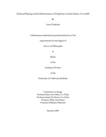
of the piston. Usually a cylinder is bored in a cylinder block. A gasket, madeof copper sheet or asbestos is inserted between the cylinder and the cylinderhead. The combustion space is provided at the top of the cylinder head wherecombustion takes place. There is a rod called connecting rod for connectingthe piston and the crankshaft. A pin called gudgeon pin or wristpin isprovided for connecting the piston and the connecting rod of the engine. Theend of the connecting rod which fits over the gudgeon pin is called small endof the connecting rod. The other end which fits over the crank pin is calledbig end of the connecting rod. The crankshaft rotates in main bearings whichare fitted in the crankcase. A flywheel is provided at one end of the crankshaftfor smoothening the uneven torque, produced by the engine. There is an oilsump at the bottom of the engine which contains lubricating oil for lubricatingdifferent parts of the engine (Fig.1).Fig. 1. Working components of I.C.Engine2.4 Engine componentsInternal combustion engine consists of the following parts (Fig.2):Cylinder: It is a part of the engine which confines the expanding gases andforms the combustion space. It is the basic part of the engine. It providesspace in which piston operates to suck the air or air-fuel mixture. The pistoncompresses the charge and the gas is allowed to expand in the cylinder,transmitting power for useful work. Cylinders are usually made of high gradecast iron.6
Fig. 2.Components of I.C.EngineCylinder block: It is the solid casting which includes the cylinder and waterjackets (cooling fins in the air cooled engines).Cylinder head: It is detachable portion of an engine which covers thecylinder and includes the combustion chamber, spark plugs and valves.Cylinder liner or sleeve: It is a cylindrical lining either wet or dry which isinserted in the cylinder block in which the piston slides. Cylinder liners arefitted in the cylinder bore and they are easily replaceable. The overhaulingand repairing of the engines, fitted with liners is easy and economical. Linersare classified as: dry liner, and wet liner. Dry liner makes metal to metalcontact with the cylinder block casting. Wet liners come in contact with thecooling water, whereas dry liners do not come in contact with cooling water.Piston: It is a cylindrical part closed at one end which maintains a closesliding fit in the engine cylinder. It is connected to the connecting rod by apiston pin. The force of the expanding gases against the closed end of thepiston, forces the piston down in the cylinder. This causes the connecting rodto rotate the crankshaft. Cast iron is chosen due to its high compressivestrength, low coefficient of expansion, resistance to high temperature, ease of7
casting and low cost. Aluminum and its alloys are preferred mainly due to itslightness.Head (crown) of piston: It is top of the piston.Skirt: It is that portion of the piston below the piston pin which is designedto absorb the side movements of the piston.Piston ring: It is a split expansion ring, placed in the groove of the piston.Piston rings are fitted in the grooves, made in the piston. They are usuallymade of cast iron or pressed steel alloy. The functions of the ring are asfollows:(a) It forms a gas tight combustion chamber for all positions of piston.(b) It reduces contact area between cylinder wall and piston wall forpreventing friction losses and excessive wear.(c) It controls the cylinder lubrication.(d) It transmits the heat away from the piston to the cylinder walls.Piston rings are of two types:(a) Compression ring and (b) Oil ring.(a) Compression ring. Compression rings are usually plain, single piece andare always placed in the grooves, nearest to the piston head.(b) Oil ring. Oil rings are grooved or slotted and are located either in lowestgroove above the piston pin or in a groove above the piston skirt. Theycontrol the distribution of lubrication oil in the cylinder and the piston. Theyprevent excessive oil consumption also. Oil ring is provided with small holesthrough which excess oil returns back to the crankcase chamber.Piston pin: It is also called wrist pin or gudgeon pin. Piston pin is used tojoin the connecting rod to the piston. It provides a flexible or hinge likeconnection between the piston and the connecting rod. It is usually made ofcase hardened alloy steel.Connecting rod: It is a special type of rod, one end of which is attached tothe piston and the other end to the crankshaft. It transmits the power ofcombustion to the crankshaft and makes it rotate continuously. It is usuallymade of drop forged steel.8
Crankshaft: It is the main shaft of an engine which converts thereciprocating motion of the piston into rotary motion of the flywheel. Usuallythe crankshaft is made of drop forged steel or cast steel. The space thatsupports the crankshaft in the cylinder block is called main journal, whereasthe part to which connecting rod is attached is known as crank journal.Fly wheel: Fly wheel is made of cast iron. Its main functions are as follows:(a) It stores energy during power stroke and returns back the same energyduring the idle strokes, providing a uniform rotary motion by virtue of itsinertia.(b) It also carries ring gear that meshes with the pinion of the starting motor.(c) The rear surface of the flywheel serves as one of the pressure surfaces forthe clutch plate.(d) Engine timing marks are usually stamped on the flywheel, which helps inadjusting the timing of the engine.(e) Some times the flywheel serves the purpose of a pulley for transmittingpower.Crankcase: The crankcase is that part of the engine which supports andencloses the crankshaft and camshaft. It provides a reservoir for thelubricating oil of the engine.Cam shaft: It is a shaft which raises and lowers the inlet and exhaust valvesat proper time. Camshaft is driven by crankshaft by means of gears, chains orsprockets. The speed of the camshaft is exactly half the speed of thecrankshaft in four stroke engine. Camshaft operates the ignition timingmechanism, lubricating oil pump and fuel pump. It is mounted in thecrankcase, parallel to the crankshaft.Timing gear: Timing gear is a combination of gears, one gear of which ismounted at one end of the camshaft and other gear on the end of the end ofthe crankshaft. Camshaft gear is bigger in size than that of the crankshaft gearand it has twice as many teeth as that of the losing crankshaft gear. For thisreason, this gear is commonly called Half time gear. Timing gear controls thetiming of ignition, timing of opening and closing of valves as well as fuelinjection timing.9
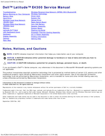
Inlet manifold: It is that part of the engine through which air or air-fuelmixture enters into the engine cylinder. It is fitted by the side of the cylinderhead.Exhaust manifold: It is that part of the engine through which exhaust gasesgo out of the engine cylinder. It is capable of with-standing high temperatureof burnt gases. It is fitted by the side of the cylinder head.2.5 Internal engine classificationInternal combustion engines are classified in two types depending on theperiod required to complete a cycle of operation. They are four stroke and twostroke engines.1. When the cycle is completed in two revolutions of the crankshaft, it iscalled four stroke cycle engines.2. When the cycle is completed in one revolution of the crankshaft, it is calledtwo stroke cycle engines.I.C. engines are of two types: (i) Petrol engine (carburetor type, spark ignitionengine), and (ii) diesel engine (compression ignition engine).Petrol engine: It is the engine, in which liquid fuel is atomized, vaporizedand mixed with air in correct proportion before entering onto the enginecylinder during suction stroke. The fuel is ignited in the cylinder by anelectric spark.Diesel engine: In this engine, during suction stroke, only air is entered intothe cylinder and compressed. The fuel is injected through fuel injectors andignited by heat of compression.2.5.1 Working of four stroke cycle engineIn four stroke cycle engine, all the events taking place inside the enginecylinder are completed in four strokes of the piston i.e., suction, compression,power and exhaust stroke (Fig.3). This engine has got valves for controllingthe inlet of charge and outlet of exhaust gases. In two stroke cycle engine, allthe events take place in two strokes of the piston.10
The four strokes of the piston are as follows:1. Suction stroke: During this stroke, only air or mixture of air and fuel aredrawn inside the cylinder. The charge enters the engine through inlet valvewhich remains open during admission of charge. The exhaust valve remainsclosed during this stroke. The pressure in the engine cylinder is less thanatmospheric pressure during this stroke.2. Compression strike: The charge taken in the cylinder is compressed bythe piston during this stroke. The entire charge of the cylinder is compressedto a small volume contained in the clearance volume of the cylinder. If onlyair is compressed in the cylinder (as in the case of diesel engine), the fuel isinjected at the end of the compression stroke. The ignition takes place due tohigh pressure and temperature. If the mixture of air and fuel is compressed inthe cylinder (as in the case of spark ignition engine i.e., petrol engine), themixture is ignited by spark plug. After ignition, tremendous amount of heat isgenerated, causing very high pressure in the cylinder which pushes the pistonbackward for useful work. Both valves are closed during this stroke.3. Power stroke: During power stroke, the high pressure developed due tocombustion of fuel causes the piston to be forced downwards. The connectingrod with the help of crankshaft transmits the power to the transmission systemfor useful work. Both valves are closed during this stroke.4. Exhaust stroke: Exhaust gases go out through exhaust valves during thisstroke. All the burnt gases go out of the engine and the cylinder becomesready to receive the fresh charge. The inlet valve is closed and exhaust valveremains open during this stroke. The exhaust valve is closed just after the endof the exhaust stroke, and the inlet valve is opened just before the burning ofthe suction stroke to repeat the cycle of operation.Thus it is found that out of four strokes, there is only one power strokeand three idle strokes. The power stroke supplies necessary momentum foruseful work.11
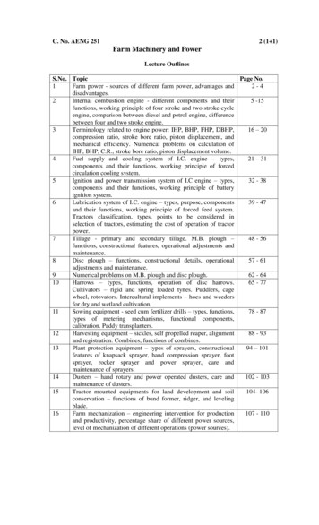
Fig. 3. Working of four stroke cycle engine2.5.2 Two stroke cycle engineIn such engines, the whole sequence of events i.e. suction, compression,power and exhaust are completed in two strokes of the piston and in onecomplete revolution of the crankshaft (Fig.4). There is no valve in this type ofengine. Gas movement takes place through holes called ports in the cylinder.The crankcase of the engine is gas tight in which the crankshaft rotates.Fig. 4. Working of two stroke cycle engine12
First stroke (suction compression): When the piston moves up the cylinder,it covers two of the ports, the exhaust port and the transfer port, which arenormally almost opposite to each other. This traps a charge of fresh mixturein the cylinder and further upward movement of the piston compresses thischarge. Further movement of the piston also uncovers a third port in thecylinder suction port. More fresh mixture is drawn through this port into thecrankcase. Just before the end of this stroke, the mixture in the cylinder isignited as in the four stroke cycle.Second stroke (Power exhaust): The rise in pressure in the cylinder causedby the burning gases forces the piston to move down the cylinder. When thepiston goes down, it covers and closes the suction port, trapping the mixturedrawn into the crankcase during the previous stroke then compressing it.Further downward movements of the piston uncover first the exhaust port andthen transfer port. This allows the burnt gases to flow out through exhaustport. Also the fresh mixture under pressure in the crankcase is transferred intothe cylinder through transfer port during this stroke. Special shaped pistoncrown deflect the incoming mixture up around the cylinder so that it can helpin driving out the exhaust gases.When the piston is at the top of its stroke, it is said to be at the top deadcentre (TDC). When the piston is at the bottom of its stroke, it is said to be atits bottom dead centre (BDC). In two stroke cycle engine, both the sides ofthe piston are effective, which is not the case in case of four stroke cycleengine.Scavenging: The process of removal of burnt or exhaust gases from theengine cylinder is known as scavenging. Entire burnt gases do not go out innormal stroke, hence some type of blower or compressor is used to removethe exhaust gases in two stroke cycle engine.13
2.6 Comparison between diesel and petrol (carburetor) enginesS.No.Diesel enginePetrol engine1.Diesel fuels are used.Vapourizing fuels such as petrol,powerine or kerosene are used.2.Air alone is taken in duringsuction stroke.Fuel is injected into superheated air of the combustionspace where burning takesplace.Mixture of air and fuel is taken in.3.Air-fuel is compressed in thecombustion chamber where it isignited by an electric spark.4.Air-fuel ratio is not constant Air and fuel are almost always in theas the quantity of air drawn ratio of 15:1, but to vary the engineinto the cylinder is always power, quantity of mixture is varied.the same. To vary the loadand speed the quantity offuel injected is changed.5.Compression ratio of the Compression ratio of the engineengine varies from 14:1 to varies from 5:1 to 8:1.20:1.6.Specific fuel consumption is Specific fuel consumption is aboutabout 0.2 kg per BHP per 0.29 kg per BHP per hour.hour.7.4.5 litres of fuel is sufficient 4.5 litres of fuel will last about 12 hpfor nearly 20 hp hour.hour.8.Diesel engine develops This characteristic is not present inmore torque, when it is carburetor engines.heavily loaded.9.Thermal efficiency varies Thermal efficiency varies betweenbetween 32 and 38%.25 and 32%.10.It runs at a lower Combustion gas temperaturetemperature on part load.slightly higher under part load.11.Engine weight per horse Engine weight per horse power ispower is high.comparatively low.12.Initial cost is high.Initial cost is low.13.Operating cost is low.Operating cost is comparatively high.14is
2.7 Comparison between two stroke and four stroke enginesS.No. ParticularsFour stroke engineTwo stroke engine1.one power stroke forone power strokeevery two revolutionsfor each revolutionsof the crankshaftof the crankshaft2.3.No. of power strokePower for the same SmallLarge (about 1.5cylinder volumetimes of 4 stroke)Valve mechanismPresentPorts instead ofvalves4.Construction and costComplicatedand Simple, cheapexpensive5.Fuel consumptionLittleHigh (about 15%more)6.Removal of exhaust EasyDifficultgases7.DurabilityGoodPoor8.Stability of operationHighLow9.LubricationEquippedwithan Using fuel, mixedindependentwith lubricating oillubricating oil circuit10.Oil consumption11.Carbon deposit inside Not so muchMuch because ofcylindermixed fuel12.NoiseLittleMuchSuction & exhaust is Suction & exhaustnoiseless, but other is noiseless, butworking is noisyother working isnoise less13.Air tight of crankcaseUn necessaryMust be sealed14.CoolingNormalChances ofoverheating15.Self weight and sizeHeavy & large15Light & small
Lecture No.3Terminology related to engine power: IHP, BHP, FHP, DBHP, compression ratio,stroke bore ratio, piston displacement, and mechanical efficiency. Numerical problemson calculation of IHP, BHP, C.R., stroke bore ratio, piston displacement volume.3.0 Engine TerminologyFig.5. Diagram showing TDC and BDC positionsBore : Bore is the diameter of the engine cylinder (Fig.5).Stroke : It is the linear distance traveled by the piston from Top dead centre(TDC) to Bottom dead centre (BDC).Stroke-bore ratio: The ratio of length of stroke (L) and diameter of bore (D)of the Cylinder is called Stroke-bore ratio (L/D). In general, this ratio variesbetween 1 to 1.45 and for tractor engines, this ratio is about 1.25.Swept volume (Piston displacement): It is the volume (A x L) displaced byone stroke of the piston where A is the cross sectional area of piston and L isthe length of stroke.Compression ratio: It is the ratio of the volume of the charge at thebeginning of the compression stroke to that at the end of compressionstroke, i.e., ration of total cylinder volume to clearance volume.Compression ration of diesel engine varies from 14:1 to 20:1, carburetorengine varies from 4:1 to 8:1.Power : It is the rate of doing work. Unit of power in SI units - Watt(Joule/sec).16
Horse power: It is the rate of doing work. One HP is equivalent to 75 kg-m /sec.Indicated Horse Power (IHP): it is the total horse power developed by allthe cylinders and received by pistons, without friction and losses within theengine.IHP PLAN4500n2IHP PLANn4500(for four stroke engine)(for two stroke engine)Where P - Mean effective pressure in Kg/cm2L- Length of the piston stroke in metersA -Cross sectional area of piston in cm2N- rpm of the enginen - Number of cylinders in the engineBrake horse power (B.H.P): It is the horsepower delivered by the engineand is available at the end of the crankshaft and it is measured by suitabledynamometer.Frictional horse power (F.H.P): It is the power required to run the engine ata given speed with out producing any useful work. It represents the frictionand pumping losses of the engine.F.H.P I.H.P - B.H.PI.H.P B.H.P F.H.PDrawbar horse power (DBHP): It is the power of a tractor measured atthe end of the drawbar. It is the power required to pull the loads.Brake mean effective pressure ( BMEP): It is the average pressureacting throughout the entire power strokes which are necessary to produceBHP of the engine.BMEP BMEP BHP 75 60nL A N2BHP 75 60L A N nThermal efficiency:(for four stroke engine)(for two stroke engine)It is the ratio of the horse power output of theengine to the fuel horse power.17
Mechanical efficiency: It is the ratio of the brake horse power to theindicated horse power.Mechanical efficiency Piston speed (Np)BHP100IHP: It is the total length of travel of the piston in acylinder in one minute. Piston speeds of the high speed tractor engine rangebetween 300 to 500 m/m.Displacement volume (Vd) : It is the total swept volume of all thepistons during power strokes occurring in a period of one minute.Vd ALnA – piston areaL – piston strokeN – number of power strokes per minute for all cylinders.Example 1: Calculate the BHP of a 4 stroke, 4 cylinder I.C. Engine which hascylinder bore of 14 cm, stroke length of 16 cm, crankshaft speed of 1100rpm, frictional horse power of 30, and mean effective pressure is 8 kg/cm2.Solution:Data given: D 14 cm ; L 16 cm; N 1100 rpm; FHP 30 and P 8 kg/cm2IHP PLAN45008 0.16IHP n2(for four stroke engine)1424450011004 96.42I.H.P B.H.P F.H.PBHP IHP – FHP 96.4 – 30 66.4Example 2: The horse power developed at the end of crankshaft of a 4 stroke,4 cylinder I C engines was found to be 30 HP at a speed of 1500 RPM. Themean effective pressure is 6 kg/cm2 .The stroke-bore ratio is 1.3. Find thelength of stroke and diameter of bore if the mechanical efficiency is 80%.Solution:Data given: BHP 30; N 1500; P 6 kg/cm2;1880%
BHP100IHPMechanical efficiency IHP IHP BHP PLAN450030 100 37.580n2(for four stroke engine)Stroke-bore ratio 6 1.3DIHP LDD1.3215004450037.5 4.08 D3L 1.3 D42D 2.1 cmL 1.3 2.1 2.7 cmExample 3: A Four cylinder four stroke diesel engine has a cylinder diameterof 20 cm, stroke-bore ratio is 1.45, clearance volume 4508 cm3, engine speed250 rpm, mean effective pressure 6.8 kg/cm2 and mechanical efficiency is75%. Calculate (i) IHP, (II) BHP (iii) Compression ratio and (iv) Sweptvolume.Solution:Data given: D 20 cm; N 250; P 6.8 kg/cm2;clearance volume 4508 cm2Stroke-bore ratio LD1.45Where D 20 cmL 1.45 20 29 cm(i) IHP PLAN45006.8 0.29IHP n244500(for four stroke engine)202250(ii) Mechanical efficiency BHP IHP100 4 68.92BHP100IHP68.9 75 51.71001975%
(iii) and (iv) Compression ratio: Swept volume Clearence volumeClearence vol
1.2 Animal power The most important source of power on the farm all over the world and particularly in India is animal. It is estimated that, nearly 80% of the total draft power used in agriculture throughout the World is still provided by animals. India is havi