Transcription
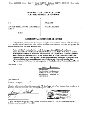
5002/5005 Bike Repair Guide5002 recumbent bikeVersion 2; Date: 10-26-045005 upright bikeNote: Electronics in 5002 and 5005 are basically the same, but displays differ.Unique Technical Features of 5002/5005 Bikesz An alternator (in the flywheel) produces AC current.zzzTo replace an alternator, replace the whole flywheel.There is no optic sensor; speed is calculated based on Hz from thealternator.If the alternator produces power but no steps-per-minute value appearson the display, replace the drive board.Resistance – “Eddy Current System” – electro-magnetBattery – 6 VDC – Supplies power to display when alternator is not operatingDisplay – Dot matrix – 5002 and 5005 displays are not interchangeable
5002/5005 Bike Repair Guide – Table of Contents5002/5005 Bike Operation Overview1.0Alternator Power Up ProcessAlternator Output – at FlywheelAlternator Output – at Drive Board2.02.12.2Battery Power ON Process3.0Battery Recharge ProcessBattery Voltage Test – at Drive BoardBattery Recharge Test – at Drive Board4.04.14.1Resistance – “Eddy Current System”Resistance Voltage Test – at Drive BoardMagnet OHM Test5.05.15.2Remote (5002)Remote Control – Battery LocationRemote Control and OverlayRemote Control Power Supply TestRemote Control Signal Test6.06.16.16.26.2Tips for Troubleshooting Mechanical Issues7.0Note: Section headings are shown in bold.Version 1: May 2003Version 2: Oct. 26, 2004 – corrections were made; pages were renumbered.0.0
Operation OverviewDisplayRibbon CableAlternatorDiagram Key:Drive BoardMagnetPowerSignal1) User pedals the bike. The alternator supplies AC voltage.2) Drive board converts AC voltage to DC voltage. DC voltage from the driveboard powers the display.3) User presses display key or remote key. Signal travels from the display tothe drive board.4) Drive board supplies DC power according to signal from the display formagnet operation.1.0
Alternator Power Up ProcessDisplayRibbon CableAlternatorDiagram Key:Drive BoardPowerSignalExplanation1) Exercise on the bike. The flywheel spins.2) The alternator produces AC voltage.3) Power conducts across the yellow wires from the alternator to the driveboard.4) The drive board converts AC voltage from the alternator to DC voltage andsends 5 VDC up the ribbon cable to the display board.5) The display receives 5 VDC power supply and lights up.6) The drive board uses the Hz cycle from the alternator as a speed signal,which it sends to the display.7) The display IC calculates rotations per minute based on the speed signalfrom the drive board. The speed value appears as RPMs on the display.Symptom of Alternator MalfunctionExercise on the unit. Display does not light up. There is no power from thealternator. Press the display ON key; the display lights up.Troubleshooting1) Inspect 3-amp alternator fuse. Replace if necessary.2) Test alternator output. See page 2.1 and 2.2.2.0
Alternator Output – at FlywheelPut multimeter to the VAC setting. Insert probes into the yellow wireconnectors near the flywheel. Pedal on the bike. Voltage will vary dependingon speed. No voltage whatsoever indicates a bad alternator.2.1
Alternator Output – at Drive BoardPut multimeter to the VAC setting. Place probes into the yellow wireconnectors on the drive board. Voltage will vary depending on speed. Novoltage whatsoever indicates a bad alternator.2.2
Battery Power ON ProcessKeypad / OverlayDisplay BoardRibbon CableDrive BoardDiagram Key:BatteryPowerSignalExplanation1) Battery voltage lies waiting for action. Press the display ON key.2) The signal travels from the keypad, to the display, to the drive board.3) The battery supplies power through the drive board, via the ribbon cable, tothe display. The display lights up.3.0
Battery Recharge ProcessAlternatorDiagram Key:Drive BoardBatteryPowerSignalExplanation1) Exercise on the bike. The flywheel spins.2) The alternator produces AC voltage.3) Power from the alternator conducts across yellow wires to the drive board.4) Drive board converts AC power to DC power and sends DC power to thebattery.5) The battery recharges, enabling it to power the unit.Symptom of Battery MalfunctionDo not exercise on the unit. Press the keypad ON key. The display does notlight up.Troubleshooting1) Check 3-amp fuse on the battery wires. Replace if necessary.2) Battery voltage test. See page 4.1.3) Battery recharge test. See page 4.1.4.0
Battery Voltage Test – at Drive BoardPut multimeter to the DC voltage setting. Put probes on the red and black wireconnector on the drive board. Normal reading: 6 VDC. If there is less than6VDC, try recharging the battery by exercising on the unit. Alternative testlocation: battery terminals.Battery Recharge Test – at Drive BoardTest goal: to determine whether the alternator and drive board are supplyingpower to recharge the battery.Keep multimeter probes as shown above. Put multimeter to the VDC setting.Exercise on the unit. Normal reading: 6.50 VDC. If the drive board doesn’tsupply voltage to recharge the battery, inspect the alternator, wires, and driveboard. If the alternator and wires are OK but the drive board isn’t supplyingpower to recharge the battery during operation, replace the drive board. If thebattery receives 6.5 VDC for 15 minutes but doesn’t hold the charge, replacethe battery.4.1
Resistance – “Eddy Current System”Display BoardAlternatorDiagram Key:Drive BoardMagnetPowerSignal1) Alternator supplies voltage to the drive board.2) User presses display LEVEL up or down key. Signal travels via the ribboncable from the display to the drive board.3) The drive board provides voltage for the magnet according to the displayboard level signal.The higher the voltage supplied to the magnet, the more resistance, the moredifficult it is to pedal. The lower the voltage supplied to the magnet, the lessresistance, the easier it is to pedal.Symptom of Magnet Malfunction1) Exercise on the unit. Press LEVEL up; there is no resistance.Troubleshooting1) Drive board resistance voltage test. See page 5.1.2) Magnet OHM test. See page 5.2.5.0
Resistance Voltage Test – at Drive BoardPut multimeter to the VDC setting. Back probe on the two blue wire connectorson the drive board. See picture below.Press LEVEL up key while exercising on the bike. Readings will vary but anapproximate guide follows.RPMLEVELVDC3012.33056301010301412If readings are similar to those shown above, then the drive board is providingvoltage for the magnet. The drive board is OK. If the voltage reading is normal,inspect the magnet. See 5.2.5.1
Magnet Ohm TestDetach magnet wire connections at the drive board. Put multimeter to the ohmsetting. Place meter probes on the blue wire ends that lead to the magnet.Normal reading: 20 ohm, - 20%. If less than 17 ohm, replace theelectro-magnet.5.2
Remote Control (5002 Only)RemoteDiagram Key:ReceiverDisplayDrive BoardMagnetPowerSignalExplanation1) Press a key on the remote control handle.2) Remote transmitter sends its signal to the receiver.3) The remote receiver receives the signal from the transmitter.4) The receiver sends signals through the wires labeled “remote” to the driveboard.5) The signals travel the ribbon cable to the display.6) The display board sends signals (commands) to the drive board.7) The drive board supplies power for magnet operation.8) Magnet operates according to voltage supplied.Symptom of MalfunctionPress remote control keypad keys. Display does not beep or respond to signal.Troubleshooting1) Change batteries in the remote control transmitter on the handlebar.Transmitter requires two AAA 1.5 VDC batteries. See picture on page 6.1.2) Inspect the overlay on the transmitter. Are keys cracked? If so, replace theoverlay. See picture on page 6.2.3) Clean the receiver (black square) at the base of the unit in front of the user’sright foot. Inspect the floor. Put a shiny magazine on the ground in front of thereceiver. (Sometimes the signal doesn’t bounce off dark or carpeted surfaceswell.)4) Replace the transmitter.5) Replace the receiver.6.0
5002 Remote Control – Battery LocationRemote control batteries are under the transmitter.5002 Remote Control OverlayRemote control and overlay6.1
Remote Control Power Supply TestPut multimeter to the VDC setting. Place probes on the two outside wires onthe remote control wire connector. Turn on bike power. Normal reading: 5 VDC.A normal reading indicates that the drive board is supplying power to theremote receiver.Remote Control Signal TestLeave one probe in place. Put the other on the inside wire as shown. Operatethe remote. Normal condition: When the signal goes through, the voltagejumps suddenly, and the display beeps once.6.2
Tips for Troubleshooting Mechanical Issues1) Resistance slips when pedaling forward.Inspect: drive pulley. Remove the belt and pull the drive pulley to the side. If itwobbles, replace the drive pulley.2) You can pedal backward but not forward.Inspect: flywheel. To inspect the bearings, remove the belt and pull theflywheel to the side. If it wobbles, replace the drive pulley.3) Unit makes odd sounds.Thump on 5002. Inspect the leveler in the middle of the 5002. If it is set toohigh, the unit will rock back and forth, making a “thump, thump” sound.Belt noises. Inspect belt grooves for wear. Replace belts if necessary. For aquick fix, spray belt dressing on the belt. If the noise disappears, considerreplacing the belt anyway, because once the dressing dries, the noise willprobably reappear.Others. Trace the sound to its origin. Realign, repair, or replace the part.4) Crank arms fall off.Inspect the axle and crank arm nut threads. If they are good, retighten. Ifthreads are stripped, replace the part. Reinstall the crank arm. Reseat bytightening the crank arm nut. Then tap the crank to see if it will seat better.Tighten crank arm nut using full force.5) Pedals fall off.Inspect pedal and crank threads. If stripped, replace the part. If not, reinstall.Tighten well.7.0
5002/5005 Bike Repair Guide Version 2; Date: 10-26-04 5002 recumbent bike 5005 upright bike Note: Electronics in 5002 and 5005 are basically the same, but displays differ. Unique Technical Features of 5002/5005 Bikes z An alternator (in the flywheel) produces AC current