Transcription
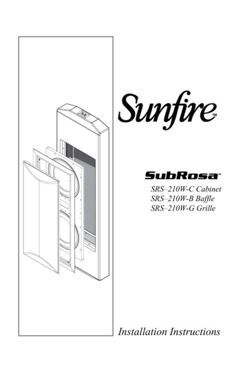
SRS–210W-C CabinetSRS–210W-B BaffleSRS–210W-G GrilleInstallation Instructions
SafetyImportant Safety Instructions1. Read Instructions2. Keep these Instructions3. Heed all Warnings.4. Follow all Instructions5. Do not use this apparatus near water.6. Clean only with dry cloth.7. Do not install near any heat sources suchas radiators, heat registers, stoves, orother apparatus (including amplifiers) thatproduce heat.8. Unplug this apparatus during lightningstorms or when unused for long periodsof time.9. Refer all servicing to qualified servicepersonnel. Servicing is required whenthe apparatus has been damaged in anyway, such as a power-supply cord or plugis damaged, liquid has been spilled orobjects have fallen into the apparatus, theapparatus has been exposed to rain ormoisture, does not operate normally, orhas been dropped.10. Installation should only be performedby qualified and experienced professionalinstallers. Refer to your Sunfire dealer.The SubRosa subwoofer is a finelytuned system and should only beused with the Sunfire SRA-2700EQcompanion amplifier. Using any otheramplifier will offer inferior performance andmay void your warranty.WARNING:THIS SUBWOOFER SYSTEM IS CAPABLE OFPRODUCING VERY HIGH SOUND PRESSURE LEVELS. YOUMUST TAKE EVERY PRECAUTION TO PROTECT YOURHEARING FROM PERMANENT DAMAGE. User's Manual
CabinetContentsBaffle InstallSafety Instructions. 2Introduction. 4Unpacking. 5Dimensions. 6Location. 7Framing. 9Cabinet installation. 10Wiring. 11Final rough-in. 12Horizontal mounting. 14Baffle installation. 16Grille installation. 18Grille InstallFor more information on this and other Sunfireproducts, please visit our website:www.sunfire.comUser's Manual
IntroductionIntroductionThank you for purchasing this SunfireSubRosa Subwoofer. We hope youenjoy it and the music it makes as muchas we have enjoyed creating it for you.The breakthrough features of thesubwoofer include: I-BEAM anti-shake mechanism toreduce wall vibration Dual ten-inch, High Back-emf woofers with neodymium magnets forlow-profile 2700W Tracking Downconverter companion amplifier Fully automatic room equalizationThe SubRosa subwoofer is a finelytuned system and should only beused with the Sunfire SRA-2700EQcompanion amplifier. Using any other amplifier will offer inferior performance andmay void your warranty.System componentsThe required components for a functioning SubRosa in-wall system are: SRS-210W-CIn-wall cabinet and hardware. SRS-210W-BFront baffle containing two woofers,the I-BEAM anti-shake device,and a crossover network. SRS-210W-GGrille assembly SRA-2700EQAmplifier and its room equalizationmeasurement microphoneAbout this installation guideThis guide contains instructions forinstalling the SubRosa in-wall cabinet intovarious locations, and installing the frontbaffle assembly, and the grille assembly.For information regarding the operation of the system, please refer to theuser's guide that comes with thecompanion SRA-2700EQ amplifier.Tools and experiencerequiredThe cabinet should only beinstalled by qualified and experienced professional installers.General construction tools are requiredfor framing wood studs, gluing andscrewing the cabinet in place, and applying sheetrock. User's Manual
The cabinet may be mounted verticallybetween wall studs. The width is ideal forfitting between vertical 2x4 studs, spaced16 inches apart. It may also be fittedhorizontally.A cardboard debris shield is suppliedto fill the front aperture and prevent anydust, paint, or debris from entering duringinstallation and sheetrock finishing.Strips of foam material are supplied tofit between the cabinet and the studs andsheetrock.Contents of each packageSRS–210W-C cabinet Cabinet assemblyDimensions 44.50" x 14.25" x 3.5"1,130.3 mm x 362 mm x 88.9 mmWeight 23.30 lb (10.6 kg) Debris shield12 foam strips 1" x 5"8 foam strips 1" x 8"Plastic rivets for debris shield12 wood screwsSRS–210W-B baffle assembly Baffle assemblyDimensions 26.75" x 11.75" x 3.25"679.5 mm x 298.5 mm x 82.6 mmWeight 29 lb (13.2 kg) 14 Allen head screws and washers(8-32 x 1.25")The cabinet should be firmly andpermanently joined to the studwork andsheetrock using woodscrews and glue.The woofer baffle assembly is screwedto the front of the cabinet once the sheetrock is in place. A grille frame and grilleare added to finish the installation. A paintshield is supplied so that you can easilypaint the grille at the same time as thewalls are painted.UnpackingTwo people are required to gently lift outthe cabinet and the baffle assembly fromtheir shipping boxes. Remove all thepacking material.Your Sunfire subwoofer should reachyou in perfect condition. If you do noticeany shipping damage, please contactSunfire immediately. Make sure that youkeep your sales receipt. It is the only wayto establish the duration of your LimitedWarranty and it may come in useful forinsurance purposes.The serial number for the SubRosasubwoofer is printed on the front label ofthe woofer assembly.User's ManualSRS–210W-G grill assembly Grille frameDimensions 28.80" x 13.8" x 0.7"731.5 mm x 350.5 mm x 17.78 mm(includes drywall spacer)Weight 2.00 lb (0.9 kg) GrilleDimensions 26.5" x 11.5" x 0.75"673.1 mm x 292.1 mm 19.1 mmWeight 0.6 lb (0.27 kg) Paint shield12 Allen head screwsSRA–2700EQ amplifier SubRosa amplifierDimensions 1.75" (1U) x 17" x 15"44.5 mm x 431.8 mm x 381 mmWeight 18.4 lb. (8.35 kg) Room measurement microphonewith stand and cordAC power cord2 rack-mount brackets IntroductionInstallation overview
Front ViewSide ViewBack View44.500 in/1,130.3 mm35.590 in/904 mm8.830 in/224.3 mm26.76 in/679.7 mm10.717 in/ 272.2 mm13.045 in/ 331.343 mm14.250 in/ 362 mm3.533 in/ 89.7 mm001.261 in/ 32.1 mmDimensionsDimensions3.500 in88.9 mmFront Cutoutrequired in wallto fit woofer assembly11.784 in/299.3 mm User's Manual
LocationLocationThe suggestions below will typically result in outstanding performance.However, although low frequencies arenon-directional, factors such as roomreflections, standing waves, resonanceand absorption will strongly affect yoursubwoofer’s performance.Since your SubRosa subwoofer is designed to be professionally installed intoyour wall, engineering services from yourAuthorized Sunfire Dealer and/or outsideacoustical resources should be considered to ensure optimum performance.The SubRosa amplifier’s Auto EQfeature will tailor the sound to the roomfor optimum performance in the locationyou choose.Keep the subwoofer at leasttwo or three feet away from anyTV screen, computer, VCR ormagnetic tapes and discs. This willreduce the chance of the magnetic fieldsupsetting the TV screen or erasing yourmagnetic media.Corner installationInstalling the subwooferon the front wall, towards thecorner will reinforce the lowfrequencies.This is best suited for: Rooms larger than 200square feet where asingle subwoofer will beused, For dedicated hometheaters For listeners who enjoy“heavy” bass.User's ManualCorner location
Center locationLocationInstalling the subwoofercloser to the center of the frontwall will still provide adequatebass, but will tend to be less“heavy” and somewhat tighter.This is ideally suited for: For rooms smallerthan 200 square feet Dedicated musiclistening rooms.Central locationUsing Two SubwoofersIf you wish to use two subwoofers, the sound output will double. Locating thesubwoofers on the front wall, with one towards each corner will provide more flexibility incrossover points, without causing localization that can happen with subwoofers locatedon side and rear walls. Sunfire preamplifiers and receivers feature multiple subwooferoutputs for these applications. If your preamplifier has a single sub/LFE output, use a Ycable to split it into two outputs.Corner locationfor two subwoofers User's Manual
Vertical mountingDue to residential construction methods, vertical mounting of the cabinet isrecommended. The subwoofer cabinetwill fit between 2 x 4 inch studs on 16inch centers.Horizontal mounting is also possible,but needs additional framing steps. Seepage 10 for horizontal mounting details.1.It is recommended that you add ahorizontal brace below the cabinetto raise it above the height of thefinished floor and baseboard molding. This will prevent accidental nailpunctures in the cabinet.2.Add a horizontal brace above thesubwoofer cabinet, leaving enoughroom to make your speaker wireconnections to the push-terminals.3.Add further horizontal braces ateither side of the cabinet, butmake sure that they are at differentheights to randomize wall resonances.4.Attach self-adhesive foam strips tothe cabinet wherever there will becontact with the studs or sheetrock.Use longer strips for the sides, andshorter strips for the front face andthe shorter side resting against thelower horizontal brace.Notes: Use the illustrations as a guide,but follow all local building codesregarding the actual framing methods. The insulation stuffed inside thecabinet is required for proper operation. Do not remove the insulationduring the cabinet installation.23314Typical vertical framingUser's Manual FramingFraming
Cab InstallCabinet Installation1.With the help of an assistant tolift the cabinet, check the fit of thecabinet into the framing. Use woodshims if there is any gap betweenthe cabinet sides and the verticalstuds.2.If it makes it easier, you can connect the wiring to the cabinet beforeyou secure it in place. See the nextpage for details.3.When you are happy with the fit ofthe cabinet, apply wood glue, suchas Liquid Nails along the cabinetsides. Fit the cabinet into the framing until its front face is flush withthe front face of the framing.4.Use a level to check that the cabinet is vertical.5.Use six woodscrews (supplied) ormore on each side to secure thecabinet in place. Do not screw intoany of the joints of the cabinet. Thecabinet walls are 3/4 inch thick, somake sure the screws do not passall the way through. (The suppliedscrews will not pass through, ifused with standard 2x4 studs.)Gluing and screwing thecabinet in place10User's Manual
WiringInstall the speaker wires followingall local codes for electrical wiringinstallation. Use class 2 wiring,and 12 gauge is recommended, 16gauge is the minimum.2.Follow common low voltagepractices like avoiding high voltageelectrical wiring, or crossing themperpendicularly. This will reduce thechance of picking up hum or otherinterference.3.Make the speaker wire connections to the subwoofer terminal cup,observing the correct polarity. Theterminals are spring-loaded.4.Secure the wire to the studs withelectrical staples to prevent rattlesand movement in operation.5.Do an electrical continuity test tomake sure the connections aregood from the amplifier-end of thespeaker wire to the ends of thetwo pre-installed wires coming outfrom the inside of the subwoofer.Temporarily remove the cardboarddebris shield to reach the wires.6.Use caulk to seal the nearest cableholes to the cabinet. This will prevent air movement and secure thecables in place. Due to the natureof subwoofers, it is a good idea tosecure the wiring from vibration asmuch as possible. Do not have theweight of the cables hanging on theterminals.caulkClose-up of the spring-loadedconnectionsConnecting speakerwire to the subwooferUser's Manual11Wiring1.
Rough-inFinal Rough-in1.Make sure the debris shield is fittedinto the cabinet opening using theplastic push rivets supplied. Thiswill prevent dust and sheetrockdebris from entering the cabinet.Debris shield12User's Manual
1.Apply glue to the framing surrounding the cabinet. Also apply glueto the front surface of the cabinet,wherever it will be in contact withthe sheetrock.3.Fit the sheetrock in place withsheetrock screws spaced 4 inchesapart.4.Carefully cut away the sheetrock toreveal the cabinet's aperture. Nowthat you can see the location better,add screws to secure the sheetrockto the front face of the subwoofergluecabinet. Make sure that no screwspass close to the speaker wires orthe terminal cup.5.With the cardboard debris shield inplace, the walls can be painted andfinished as required.6.Leave the cardboard debris shieldin place until you are ready toinstall the woofer baffle assembly.It can be removed by cutting it andcarefully pulling out the rivets holding it in place.7.SheetrockSheetrock installationApplying glue forsheetrockingSee page 16 for details regardingthe installation of the woofer baffleassembly and grille frame assembly.Sheetrock over thesubwoofer installationUser's Manual13
HorizontalHorizontal mountingIn this position, the subwoofer's longestside is horizontal. This may be requiredfor some installations, although it requiresmore framing work.The procedure for mounting is basicallythe same as the vertical mounting.1.2.Attach the self-adhesive foam strips(supplied) to the cabinet whereverthere will be contact with the studsor sheetrock. Use longer strips forthe sides, and shorter strips for thefront face and the shorter verticalside.The cabinet should be mounted offthe floor as shown, to prevent nailsfrom puncturing the cabinet duringbaseboard installation.22Typical horizontal framing14User's Manual
With the help of an assistant to liftthe cabinet, check the fit into theframing, and use shims if required.4.Wiring the subwoofer is the sameas described previously, except thatthere is not much room to make theconnections to the binding posts.5.Use wood glue, such as LiquidNails along the cabinet top andside. Fit the cabinet into the framinguntil its front face is flush with thefront face of the framing.6.Use a level to make sure the cabinet is horizontal.7.Use six woodscrews or more alongthe top, and a few into the side tosecure the cabinet in place. If pos-sible, add a few screws to securethe bottom face of the cabinet. Youmay have to angle them in, but donot screw in to any of the cabinetjoints. The cabinet walls are 3/4inch thick, so make sure the screwsdo not pass all the way through.8.Do an electrical continuity test tomake sure the connections aregood from the amplifier-end of thespeaker wire to the ends of the twopre-installed wires coming out fromthe inside of the subwoofer.9.Finishing with sheetrock is thesame as described for verticalmounting. Fit the debris shieldbefore starting the sheetrock installation.10. See the next page for detailsregarding the installation of thewoofer baffle assembly and grilleframe assembly.Screwing and gluingthe subwoofer in placeUser's Manual15Horizontal3.
Woofer baffle installationWith the cabinet installed, and all thesheetrock, finishing and decorating done,the woofer baffle can be installed.Baffle InstallThe woofer baffle assembly consistsof the following components alreadyinstalled: The baffle, upon which all the components are assembled Two subwoofer drivers I-BEAM anti-shake device Crossover boardSubwooferdriverI-BEAM anti-shake deviceSubwooferdrivercrossover boardBaffleExploded view of the woofer baffle assembly(it is supplied all assembled and wired)16User's Manual
Baffle installation procedure1.Remove the debris shield from thefront of the in-wall cabinet. You cando this by cutting the cardboardwith a sharp knife and pulling outthe cardboard pieces and the plastic rivets holding it in place. Do notcut the two wires inside the cabinet,and do not remove any soundproofing material.4.Secure the woofer baffle assembly to the in-wall cabinet using 14Allen-head screws and washerssupplied. Make sure the two wiresdo not get pinched.Baffle InstallInstalling the woofer baffle assemblyRemoving the debris shield2.With the help of an assistant, holdthe baffle assembly close to thein-wall cabinet.3.Connect the two wires from theinside of the cabinet to the twopush-terminals on the crossoverboard, following this diagram:5.Before putting the grille frame andgrille on, test the subwoofer to seeif all the connections are madecorrectly. See the user's guide thatcomes with your SubRosa amplifier.Red Wire(Positive )Black Wire(Negative –)Attaching the cabinet wires to the crossoverboard fixed to the woofer baffle assembly(I-BEAM omitted for clarity)User's ManualThe woofer baffle assembly in place17
Grille installationWith the woofer baffle installed, andthe subwoofer tested, the grille can nowbe installed.PaintingThe grille assembly consists of the following components: The grille frame. This screws to thewoofer baffle and holds the grille inplace. It forms a nice frame aroundthe subwoofer opening in the wall,hiding the sheetrock edges. The grille. This pushes into thegrille frame, covering the wooferbaffle assembly and the grille framescrews from view. A paint shield is supplied to coverthe woofer baffle when painting.This allows you to paint the frameand grille at the same time thewalls are painted.The frame and grille can be painted tomatch the decor before they are installed.They come already powder coated, andcan accept a wide range of finishes.Clean them first, then take themto a well-ventilated area and paintwith care to achieve a good finish.If you prefer to paint the frame and grillewhen they are in place on the walls, thedetails are shown on the next page.Grille InstallTop viewGrille18Grille framePaint shieldUser's Manual
Installing the grille assembly1.Secure the grille frame to thewoofer baffle using 12 screwssupplied in the grille package.2.If you have already painted theframe and grille, please jump tostep 6.3.Fit the supplied cardboard paintshield into the frame to cover thewoofers and baffle. Press the grillein place temporarily.4.Paint the frame and grille to matchthe wall and decor.5.When the paint is dry, carefullyremove the grille and discard thepaint shield. (It is important toremember this step!)Carefully press the grille into theframe, and make sure it is fullypressed home on all sides.The grille installed into the frameConclusionThis completes the SubRosa in-wallsubwoofer installation.For details regarding the operation ofthe subwoofer and the automatic equalization procedure, please refer to theuser's guide that comes with the SunfireSubRosa amplifier. 2007 Sunfire Corporation.All rights reserved. Sunfire Corporationreserves the right to improve its productsat any time. Therefore, specifications andinstallation details are subject to changewithout notice.Manual 913-142-00 Rev 7User's Manual19Grille InstallLocation of the grille frame screws6.
SRS–210W-C CabinetSRS–210W-B BaffleSRS–210W-G GrilleManual 913-142-00 Rev 7
ers with neodymium magnets for low-profile 2700W Tracking Downconverter companion amplifier Fully automatic room equalization The SubRosa subwoofer is a finely tuned system and should only be used with the Sunfire SRA-2700EQ companion amplifier. Using any other am-plifier wi