Transcription
A New Concept of Planar Self-Reconfigurable ModularRobot for Conveying MicropartsBenoı̂t Pirandaa , Guillaume J. Laurentb , Julien Bourgeoisa,c , Cédric Clévyb ,Sebastian Möbesb , Nadine Le Fort-PiatbabUniversity of Franche-Comté, Montbéliard, France.Automatic Control and Micro-Mechatronic Systems Department, Institut FEMTO-ST,UMR CNRS 6174, ENSMM, Besançon, France.cComputer Science Departement, Institut FEMTO-ST, UMR CNRS 6174AbstractModularity and self-healing are two interesting properties that could helpto design more flexible conveyors of micro-objects. In the Smart Blocksproject, we propose to design a 2D modular and self-reconfigurable robotcomposed of centimeter-scale sliding blocks that embed their own actuatorsand control electronics. This article presents a proof-of-concept of the linkageand of the traveling system as well as an algorithm able to reconfigure a setof blocks from a spatial configuration to another one. Prototype blocks havebeen realized using electro-permanent magnets which show a good motionspeed while saving power consumption during the linkage. Our reconfiguration algorithm is implemented in a simulator software showing in real-timethe reconfiguration of the robot.Keywords: Electro-permanent magnets, reconfiguration, self-reconfigurablerobot, part feeder1. IntroductionConveyors are usually designed as monolithic entities solving one problemat a time. If monolithic design fits the need of fixed types of environmentsand/or objects, it lacks flexibility to environment changes and failures thatoccur at small scales [1]. Furthermore, to convey micro-objects, a MEMSbased monolithic conveyor is limited by the size of a wafer and it will usemore surface than a modular one. To solve these problems, our idea is tobuild a modular conveyor composed of hundreds of similar blocks that canPreprint submitted to MechatronicsAugust 17, 2013
detect micro-objects with sensors, move them with MEMS actuators andcommunicate with each other to form a flexible conveying path. A furtheridea is that the blocks will be able to move by themselves through the use ofside actuators to enable self-reconfigurability. A self-reconfigurable conveyorwill be able to automatically replace blocks that have failed with working ones(self-healing). Furthermore, some environments like medicinal productionhave very detailed guidelines [2] to maximize the quality of the products andto lower the possibility of product contamination. Human intervention forconveyor reconfiguration will contaminate the conveyor. There are, therefore,direct benefits to have a self-reconfigurable conveyor. Building this conveyoris the objective of a bigger project called Smart Blocks1 .Several projects have influenced our work, but the first thing to mentionis the Smart Surface project2 which is our direct predecessor. Different hardware and software systems have been developed to produce an air cushionin order to move small, flat objects. One of these, a tilted-air-jet surface,reached a size of 9mm 9mm [3] and gave therefore the target system dimensions for the Smart Blocks project. Ciliary motion systems [4] are also goodcandidates since they required only low voltages and match the target dimensions. Additionally, there were algorithms developed in order to controlmultiple sensor-actuator units with their own processor in a decentralizedway [5] and more general work conducted [6]. Other interesting ideas comefrom the modular robot field. The projects like M-TRAN [7], Superbot [8],Roombots [9] and Molecube [10] have already shown motions of autonomousparts and self-assembly albeit in bigger dimensions. The miniaturization oftheir mechanical connection systems is complex and does not seem to be theright solution for a smaller system. Another connection system has beenrealized by Neubert et al. [11] using a Fields Metal solder, melting at 60 C.This principle uses electrical heating of the contact area where the solder isdeposited, to melt it and to let it solidify again. The connection is very strongand can also be used for power or data connections. The problem is thatthere is no attraction force to move the modules. In terms of connection andattraction, the most inspiring work comes from the Pebbles project [12] usingsmall cubes (12mm 12mm), capable of forming two dimensional shapes using electro-permanent (EP) magnets. The advantage of EP magnets is smartsurface.cnrs.fr2
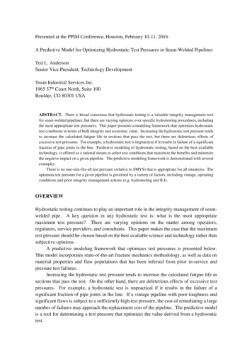
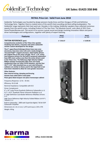
they are able to keep their polarity after a short energizing phase. However,Pebble’s cubes cannot move, they are just able to disassemble.In the Smart Surface project, we conveyed small objects using arrayedMEMS actuators. Our new modular conveyor will use these actuators so thateach block will embed arrayed-MEMS actuators on its upper face. Miniaturization of the block is one of the key aspects of the project. The final blockedge length is foreseen to be of 10 mm, including everything from supplyingthe MEMS array and connecting the blocks but also to move them. Figure 1shows a representation of the final conveyor.The focus of this article is twofold. First, we propose to use EP magnetsto design a linear motor able to move 1cm3 blocks. Using this motor, oneblock can slide on another one and can be stopped in every state keeping astrong connection without any power consumption. This means that afterthe system has formed its optimal configuration it can perform its conveyingfunction using no other resources for the linkage. Second, using this specialkind of actuation, we have also proposed a distributed reconfiguration algorithm which is able to form any 2D shape required for the conveyor. Thisalgorithm is implemented in our simulation software VisibleSim simulatingexchanges of messages and showing in real-time the reconfiguration of therobot.2. Sliding blocksThis part presents the design of a new kind of self-reconfigurable modularrobot based on sliding blocks. We propose to use EP magnets inside a linearmotor able to move blocks directly on one another.2.1. Electro-permanent (EP) magnetsThe basic part of the motor unit is the EP magnet. It consists of a coilwith a specific permanent magnet core, like AlNiCo. This material is analloy made from aluminum, nickel and cobalt which has a remanence similarto neodymium magnets (around 1.2T), but a relatively weak coercive fieldstrength around 50 to 100kA m 1 (in contrast to neodymium magnets whichhave a coercive field over 1000kA m 1 ). The result is a strong magneticforce (depending on the remanence), but also the ability of a very easy magnetization and demagnetization (depending on the coercive field strength).Wrapping a coil around the AlNiCo core, a magnetic field can be generatedto switch the magnet polarity in a very short time. The result is a bistable3
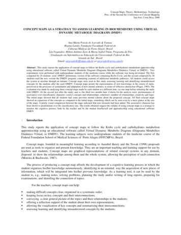
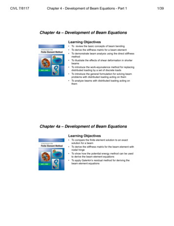
Figure 1: Example of using reconfigurable blocks for conveying objects.system, able to have an attraction or a repulsion mode like a switchablepermanent magnet.2.2. Linear motor designA linear motor is an electric motor that has its stator and rotor “unrolled”so that instead of producing a torque (rotation) it produces a linear forcealong its length. We propose to use this principle to move a “rotor” blockalong “stator” blocks. The rotor part is composed of two cylindrical 1mmby-1mm neodymium magnets. The stator part consists of three EP magnetsper blocks which have a size of around 2mm in diameter and 3mm in length.To be able to move the magnets in a chosen direction, the distance between the two neodymium magnets has to be 50% bigger than the distancebetween two EP magnets on the other side. As each block must be able tomove along one another, we put on every block two active sides, each onecontaining three EP magnets and two passive sides, each one containing twopermanent magnets. A working configuration needs to have two equal sidesnext to each other, as seen in Figure 2.The block housing, seen in Figure 2a, has been made by rapid prototyping4
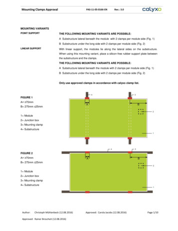
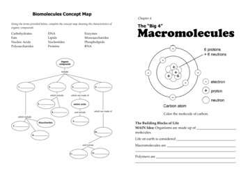
(b) Sectionalview of thelower magnetlayer(c) Sectionalview of theuppermagnet layer(a) 3D viewFigure 2: View of the linear motor units within a block with the EP and the neodymiummagnets. The block is a 10mm cube and consists of an upper and a lower part.with a fused deposition modeling machine. To build the EP magnets, theAlNiCo core which has a diameter of 1mm and a length of 3mm, has beenplaced in a vice and wrapped with 60 turns of 0.1mm enameled copper wirein three layers. To avoid uncoiling, the whole part is covered by a thin layerof cyanoacrylate-based glue. The final assembly has been done by placingand gluing all magnets in the lower part of the block, before gluing the upperpart on it. The separate parts and the final assembly can be seen in Figure 3.2.3. Electronics designTo supply the EP magnets with current in both directions a H bridge percoil is required. To reduce the number of components, we used three halfbridges linked to a shared one. As it can be seen in Figure 4, every coil hasits own half-bridge, allowing the choice of the direction of the electric currentthrough its EP magnets. Additionally there is a fourth half-bridge, able todecide which chosen current direction should be powered. Every half-bridgeconsists of two MOSFETs, a P-channel for the upper side and a N-channelfor the lower side.5
(a) Three EP magnets (withAlNiCo core) in front of twoneodymium magnets(b) Rapid prototyping parts of thecube, one block is assembled withthree EP magnets (active side, stator) and another one with two permanent magnets (passive side, rotor).Figure 3: Separate parts and an assembled blockFigure 4: Schematics of the motor unit electronics6
Because the resistance of the coil is very low, a 15V difference causesmore than 15A current in the wires. On the one hand, it would be a thermalproblem for the 0.1mm wire to be powered for more than a few micro-seconds,on the other hand, most power supply are not fast nor powerful enough toguarantee this current. Therefore, a capacitor is used to store and to deliverthe required energy.The power supply of the blocks is external. Some specific electric pushpins will be designed on lateral sides to enable the transmitting of the powerbetween blocks. However a capacitor is required in each blocks to storeenough power for a current pulse.2.4. Motor controlWith regard to a standard linear motor, we are using only two states forthe EP magnets. Actually, most electric motors are using a sinusoidal controlto reach a smooth motion. To move the “rotor” block from one “stator” toanother, six states are required. The state transition and its effect on themovement can be seen in Figure 5.If the polarization of the motor unit should show, for instance, a SSN3state, the first two half-bridge bipolar transistors will get a 5V signal, openingthe upper side transistor. The third one will stay with no signal and anopened low side transistor. Because the fourth half-bridge has got no signaland connects therefore all EP magnets to the ground, the current will flowfrom the two first upper sides over the corresponding magnets mainly to thefourth low side and to the ground. Hence, the first two magnets have beenpowered but not the last one. For this, the fourth half-bridge needs to beswitched, whereby only the third EP magnet will be powered. The result isthat if the switching of all magnets is necessary, two shots4 has to been donesuccessively.The capacitor needs some time to recharge after a shot. This time dependson the voltage supply, on the resistor in front of the capacitor and on theduration of the last shot. The capacitor voltage will therefore be read over aone to ten voltage divider with an analog-digital-converter (ADC) channel, sothat the next shot can be started as soon as the sufficient voltage is reached.3S stands for south and N for north, meaning the state of the magnetic pole that pointsoutside. It is noticeable at the block sides.4The short signal from the controller, causing an opening of certain upper side transistors and therefore the switching of one or more magnet polarities will be called “shot”.7
Figure 5: The motor state diagram shows the 6 different states of the EP magnets andthe changed position in respect to the passive sides of two blocks. The magnetic poles aremarked with S and N for South and North. As every block has two permanent magnetson each of its passive sides, six states move the “rotor” block from one “stator” to another(10mm).8
Figure 6: The timing diagram shows the signals, coming from the IC, I/O PIN are labeledfrom 0 to 3. Additionally, the voltage of the capacitor and the displacement of the blockis shown.9
Figure 7: Snapshots of the motion (six-states sequence).To generate the switching sequence presented in Figure 6, we used aMicrochip dsPIC30F4011. Four output pins are used to give the signal tothe half-bridges and one ADC input measures the capacitor voltage. In thefinal solution, we will need 8 I/O pins for running two motor units. A suitableand smaller IC from Microchip would be the 28 pin PIC16F723A in QFNdesign with a size of 4mm 4mm.3. Experimental results3.1. Motion and speedWe carried out some experiments to validate this concept of sliding blocks.The motion is stable and reproducible but a bit jerky due to on-off state transitions. Figure 7 show a complete sequence which can be further appreciatedin the video clip accompanying this paper5 .The speed of displacement has been evaluated through one hundred sequences and measuring the time. The mean speed was about 0.61s for 1cm(or 10 blocks distance in 6.1s) that is to say 16.4mm/s.5also available at this address: http://smartblocks.univ-fcomte.fr/actuationEP magnets.avi10
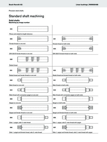
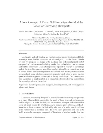
504540Force in mN3530252015105005101520253035Voltage in VFigure 8: The magnetic force between the three EP magnets of the active motor unitside and the two neodymium magnets of the passive motor unit side using a specificmagnetizing voltage and two shots.3.2. Holding force vs. VoltageWe tested the holding force between two motor units. After a proper demagnetizing, changing the polarity of all magnets while decreasing slowly theswitching voltage, we measured the force for different magnetizing voltagesusing each time two shots. We therefore put a motor unit below a secondone that is attached to a bracket. The motor units are placed as if theywere within aligned blocks. Then, we used measured balance weights, hanging them carefully on a special built anchor to the lower motor unit, untilthe connection broke. We made this several times to guarantee repeatablemeasurements of the tensile force.The result can be seen in Figure 8. Below a voltage of 6V, the magneticfield is too weak to start a proper magnetization of the AlNiCo core. From6V up to 16V, the holding force increases with the voltage. This is thelinear magnetization region of the AlNiCo. Over 16V, the magnetizationis saturated and the holding force reaches 45mN. This graph shows thatvoltages over 16V do increase the strength a lot. On the other hand, thehigher the voltage is, the longer the charge of the capacitor will be. Chargingto 18V instead of 15V takes 66% longer but increases the attraction force justby 10%. Thus, using voltages around 15V-16V is the best compromise.11
454035Force in mN30252015105001020304050Pulse duration in µsFigure 9: The magnetic force between the three EP magnets of the active motor unit sideand the two neodymium magnets of the passive motor unit side using 15V and two shotswith a specific shot time.3.3. Holding force vs. pulse durationThe next test was to check how a shorter or longer shot influences theforce. The magnets were therefore demagnetized as before and, then, magnetized with a shorter or a longer 15V shot from a 470µF capacitor. Theresult can be seen in Figure 9, showing the force function of the shot time.We found out that it is useless to increase the shot time over 25µs, becausewhile the coil is powered, the voltage of the capacitor is shrinking, causinga gradually lower current in the coil. So, after 25µs the current seems to betoo low to polarize the magnet any further.We also tested if multiple shots could increase the holding force. Wefound no hint of stronger force after ten or even hundred shots, because justa stronger magnetic field changes the remanence, the duration is irrelevantafter a certain time (25µs).3.4. Energy consumptionDuring a shot, the voltage drops around 2V. Knowing the capacitance,we can deduce that the magnets consumed an energy around 13mJ. Thatmeans that the 10mm move of a cube will consume around 78mJ.12
Figure 10: Captured image from the simulator software showing blocks with conveyingactuators on the top. The floor is covered by tracks that guide the blocks during theirdisplacement.4. Blocks reconfiguration algorithmThe travelling system presented above allows considering the developmentof blocks composed of a processing unit, sensors and actuators. Each blockis a small conveying area but, when linked with other blocks, it creates aconveying path for moving objects over larger distance. Side actuators allowa block to slide on another one and to form different conveying surfaceswith different geometries. Furthermore, it reduces cost and avoids humaninterventions to replace a defective block. The second part of this paperpresents a distributed algorithm which reconfigures a set of blocks, placingthem in a new geometrical configuration.Our algorithm allows reconfiguring a set of connected blocks consideringthat each block runs the same code and may exchange messages with 4neighbors. This algorithm consists in a finite state machine, driven by theexchanges of messages in this network of connected blocks. This algorithmis implemented in our simulator software, named VisibleSim, that shows inreal-time the exchanges of messages and the displacements of blocks (seeFigure 10).4.1. Operating principle of the blocksThe algorithm is based on exchanges of messages between neighboringblocks where each message may contain transmitted data. In order to writethis algorithm for block reconfiguration, blocks are considered as entities with13
Figure 11: Some steps of the reconfiguration algorithm: a) The goal map. b) The initialconfiguration of the blocks. c) The distance from each block to the closest empty space.d) The path from one block to a free cell.their own memory, able to execute a set of instructions. Each block is connected with 1 to 4 neighbors and communicates using asynchronous messageexchange. The algorithm presented requires only data stored within eachblock, which can run independently in autonomous units of computation.One of the blocks is chosen to propagate the actions of the reconfigurationalgorithm to the other blocks. We call this block Master Block, it is connected to an external module that manages the reconfiguration.The desired configuration is stored in a 4-way connected map, where thenumber of cells to fill corresponds exactly to the number of blocks that receive the map. Figure 11.a shows an example of a map where the cells to fillare colored in gray.4.2. Steps of the algorithmThe algorithm for blocks reconfiguration is divided into four major stages.A preliminary step, executed only once, transmits the target configurationmap to each block. After this preliminary step, three successive steps will berepeated:1. Computing the distance between blocks and empty areas,2. defining the direction of movement,3. moving the blocks.14
Each iteration is intended to make the current configuration getting closerto the target configuration.4.2.1. Sending the mapThe first step is to send the map to all the blocks (broadcast) and toreceive an acknowledgment (convergecast). The Master Block sends the mapto its neighbors. Then, when a block receives a map for the first time, itsends it to its other neighbors and waits for an answer from each of them.This stage is ending when the Master Block has received an answer fromeach of its neighbors, certifying that each block of the set has received themap.The position of each block is relative to the Master Block. During the broadcast, each map message contains coordinates of the sender so that when ablock receives a message, it deduces its position from the sender position.In order to save memory, it is possible that the entire map will not be transmitted to every block. A solution is to decompose the map into several partsand distribute these sub-maps over the sets of blocks. In the current stateof our algorithm, we are transmitting the entire map to each block, this optimization will be the subject of future enhancements.The algorithm detailed below allows to start the computation on all blocksby broadcasting (without cycles) the start order. At the end of the computation, the initial block receives an acknowledgment stating that the algorithmhas been performed on all blocks. The Figure 12 details this algorithm.We recall that the same program is executed on every block. The programbehaves like a finite state machine where the evolutions of states are triggeredby receiving messages.During the first step, the ’Master Block ’ receives the first message froman external module.For each type of information conveyed to the blocks, we define a dedicatedmessage. For example, the message called MAP MESSAGE is used to senddata about the final map. It contains the following parameters: A pointer to the transmitter block (which is necessarily a neighbor ofthe receiver), the size of the map (width and height of this area), the bit array indicating whether each cell must be filled or not,15
the transmission time is added to the message in order to simulate thetransfer delay.When a block receives a message type MAP MESSAGE, two actions arepossible:1. If there is already a map stored in the block, then it returns a messageto the sender (ACK MAP MESSAGE );2. Else, it copies the map into its memory and broadcasts a new messageMAP MESSAGE containing the map data to its neighbors (except tothe one who sent him theMAP MESSAGE ). Then, it stores the senderid of the message (in a local variable named sender ) and the numberof neighbors to whom he sent this message (in the local variable namedwaitedAnswers).When a block receives a message ACK MAP MESSAGE, it decrementsthe variable waitedAnswers. Then, if waitedAnswers is null, which indicatesthat all its neighbors have already answered, the block sends an acknowledgment to the ’sender ’ with ACK MAP MESSAGE.Figure 11.b shows the result of the map transmission to a set of blocks.Blocks that are already well placed are colored in dark gray and in light grayotherwise.4.2.2. Calculating distance between blocks and empty areasThis phase consists in searching for each block, the shortest distance to afree position in the final configuration map, as shown in Figure 11.c. In thisexample, the value placed over each block (in a myDistance variable) is thedistance from the block to the closest empty spot.This algorithm is based on two steps, each of them needing to broadcastinformation to the set of blocks. The first step initializes all distances storedin the blocks to the infinity value. Then, during the second step, each blockthat has an empty place executes the following. Using the map, it checks ifthis spot should be empty at the end of the reconfiguration. In this case, itdeduces that its distance value is equal to 1 (myDistance 1) and broadcasts this information to its neighbors.Every block must have a distance corresponding to the minimum distancefrom their neighbors plus 1. Then, to determine the distance value for eachblock when a neighbor updates its distance, it will propagate this information to its neighbors using a message containing its own distance.16
Wait for messagesMAP MESSAGE ACK MAP MESSAGEsendACK MAP MESSAGEto wers 0NOYEScopy Message.mapin local map variableisMaster Blocksender : Message.senderwaitedAnswers: 0neighbor: firstNeighborneighbor sender?YESNONOsendACK MAP MESSAGEto senderNOYESSendMAP MESSAGE(map)to neighborwaitedAnswers neighbor: next(neighbor)YESneighborexists?NOFigure 12: Algorithm of diffusion of the map over the set of blocks.17
When a block receives a message from a neighbor, it compares its own distance value (myDistance) to the received one (receivedDistance), and, updates myDistance if myDistance receivedDistance.4.2.3. Defining the direction of movementBmax is the farthest block to an empty spot. It is identified easily as itsdistance is greater than all its neighbors distance.Then, Bmax has to find a path to a block, neighbor of an empty spot. Thispath is calculated by following the decreasing distance values as shown inFigure 11.d. The neighbor of Bmax that admits the smallest distance ischosen. If distances have equal values, the order West, North, East, andSouth (WNES is here a convention) is followed. The relative position of thisneighbor defines the movement direction for the block and it is stored in thedirection variable.The two previous steps can be repeated as it exists a path linking a freeposition and a not well-placed block. In order to avoid deadlocks, we setthe distance stored in these moving blocks to the infinity value (they aremarked with in Figure 13). Thus, each block can only participate toone reconfiguration at a time but many movements of blocks are possiblesimultaneously.4.2.4. The motion of the blocksThe last step of the algorithm consists in starting the physical displacement of the blocks and waiting for them to reach their destination before beginning the next sequence. The whole movement is composed of an orderedlist of one-block movements. When two neighbors have different movementdirections, a priority has to be given to avoid collisions. The first block inthe list must wait for the second one to end its movement.4.3. The real-time simulatorWe developed a software call VisibleSim [13] to visualize in real-time thestates of the blocks during the reconfiguration algorithm. This software, developed in C , allows observation of the asynchronous execution of thecode on the different blocks.The small program associated with each block,called BlockCode, is written in C too. VisibleSim helps debug the program by changing the color of the blocks during the program or by writingdebugging text, to name a few.18
Figure 13: Algorithm for determining the direction of simultaneous displacements of manyblocks.19
Figure 14: Some screen captured from the simulator interface during the calculation ofthe reconfiguration. On the left, the last step of reconfiguration of the ’conveyor’ shape.On the right, four reconfiguration steps from the horizontal line (on the top) to the text’Mechatronics’ (on the bottom). Red blocks are already well placed, yellow blocks havejust reached their final position, and grey blocks are not well placed.The simulator calculates the simultaneous evolution of the blocks state taking into account the message transmission delay. Thus, the emission of amessage and its reception cannot be achieved simultaneously.After each movement, the positions of the blocks are displayed in real-time.Some screen captures are presented in Figure 14 and examples of reconfiguration can be visualized in a short video attached to this paper, or downloadedat this address : http://smartblocks.univ-fcomte.fr/anim blocks.mp4.4.4. Experiments on reconfiguration timeThe total reconfiguration time mainly depends on the difference betweenthe initial configuration of the blocks compared to the final map. Evenmore than the average distance traveled by each block, the complexity ofthe 4-connected path separating blocks is an important parameter of thereconfiguration complexity.We performed two types of reconfigurations, a first one defining a map witha fairly simple pattern representing a large conveyor tree (composed of 546blocks), and a more complex one formed by the text: ’Mechatronics’ (875blocks) as shown in Figure 14.For each of these situations, several initial configurations were tested: Horizontal lines: Blocks organized as horizontal lines beginning on the20
Shape GoalHorizontal line2 horizontal linesDiagonal lineSinusoidal line2 0Table 1: Number of steps to reach the goal from different initial shapes.bottom left end side and ending on the right end side. Two horizontal lines: Same as horizontal line except that lines areplaced on the top and on the bottom. Diagonal lines: Diagonal lines starting on the upper left corner andending on the lower right. Sinusoidal: a sinusoidal curve. Two vertical lines: Same as horizontal lines, except that the lines areverticals.For each configuration, the numbers of steps to reach the goal is shownin Table 1. This value represents only the number of repetitions of the algorithm required for reconfiguration without taking into account the durationof displacement of the blocks.One can notice that the speed of convergence of the algorithm variessignificantly depending on the initial configuration. The algorithm seemsto be more effective with the horizontal lines for the second case because itplaces blocks in a configuration close to their final distribution.5. ConclusionIn this paper, we proposed a proof-of-concept of a self-reconfigurablerobot based on sliding blocks. At the hardware level, several blocks havebeen realized integrating electro-permanent magnets in order to save energybetween moves. The experiments show that a block is able to move alongone another at an average speed of 16.4 mm/s and produces a holding force21
of 45mN. The blocks are powered externally but the housing of all the electronic parts in a 10mm cube is possible. A future improvement could be touse the EP magnets to sense the “rotor” block position using the differentinductance of the different positions.If the speed and e
to neodymium magnets (around 1.2T), but a relatively weak coercive eld strength around 50 to 100kAm1 (in contrast to neodymium magnets which have a coercive eld over 1000kAm1). The result is a