Transcription
Paper Speaker
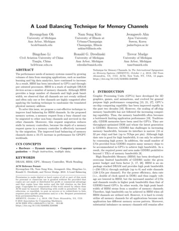
Introduction:How do you listen to music? Whether you use headphones or a large sound system you areundoubtedly using some combination of speakers, but how do speakers create sound? In this activityyou will construct your own speaker in order to learn how electromagnetism is used to fill the air withmusic.The sound we hear is a result of our brains interpreting the changes in air pressure detected byour ear drums. These changes in air pressure are what we call sound waves. When air is mechanicallycompressed and stretched the air molecules bump into each other, causing the pattern to move throughthe air where it hits your eardrum and your brain interprets it as a sound. This mechanical stretching andcompressing of the air is caused by physical objects vibrating at various frequencies in the world aroundyou. The faster the vibrations are the higher the frequency of the sound waves created, which yourbrain interprets as a higher pitched sound.A speaker is an electro‐mechanical device designed to transform electric signals into mechanicalmotions that generate sound. Sounds are typically stored on a computer as a compressed file thatcontains information about the frequency and intensity of the sound. When these files are “played” thecomputer decompresses the file and sends electric signals corresponding to the sound data throughwhatever output medium you are using. These electric signals turn on an electro‐magnet, called thevoice coil, which reverses polarity depending on the signals it is receiving. A permanent magnet, locatedeither inside the electro‐magnet, or surrounding it, forces the electro‐magnet to move up and down asthe polarity changes. This up and down motion is amplified by a diaphragm affixed to the electro‐magnet. As the diaphragm vibrates back‐and‐forth, it creates sound waves.An electro‐magnet, like the voice coil of a speaker, is created when a current moves through acoil of wire. A magnetic field is induced by the electric current according to Ampere’s Law: Integral Form. As indicated by the equation, the or equivalent Differential Form current traveling through a surface is equal to the magnetic field around a closed loop of the surface. Itis equivalent to say that the curl of the magnetic field is equal to the total current through the coilmultiplied by the permeability of free space. This equation defines how electro‐mechanical devices likespeakers and electric motors function. To get an intuitive understanding of Ampere’s Law you can usethe right hand rule. If the fingers of the right hand curl in the direction that current travels through thecoil, then the extended thumb will point in the direction of the induced magnetic field. Equivalently, ifyou point your right thumb in the direction of current flow through a wire, then when you curl thefingers on your right hand they will indicate the direction of the magnetic flux around the wire.Image taken from the Wikipedia page on the right‐hand rule.
Materials:Required: Paper plate or alternativeMagnet wireCircular neodymium magnets 12 mm x 3 mm (6)Business or note card (3)Cardboard roughly the size of the plate you usePaperGlueScissorsTapeAn old pair of headphonesAlligator clipsCellphone or computer with a 3.5mm audio jackDevice capable of recording audio data with Google Science JournalOptional: Fine grit sand paperMini amplifier3.5mm audio jack to RCA cable 12 V, 2 A DC wall adapter
Build Instructions:1. Begin by cutting two strips of paper roughly as wide as the stack of magnets you areusing is tall, and about 11 inches or about 28 cm long.2. Wrap one strip of paper tightly around your stack of magnets, securing it with a piece oftape. This paper strip is used to create a gap between the magnets and a second strip ofpaper.3. Wrap the second strip of paper around the first layer and secure it in the same manner.4. Next, carefully remove the stack of magnets from the center as well as the inner strip ofpaper. The inner layer of paper can be discarded.5. Now take the remaining outer layer of paper and begin carefully winding the magnetwire around it, leaving about a foot of wire loose to connect a signal to later. Thenumber of times to wrap the wire around the paper tube depends upon the thickness ofwire used. Refer to the table below for a few common sizes of magnet wire. Whenwrapping the wire try to keep the coil neat and any spacing between the wires even.You want the wires to lay against the paper tube, and not to pile on top of each otherWire Gauge Number of Turns2830305032606. Once the wire has been sufficiently coiled, secure the wire in place with tape, leavinganother foot of wire loose at this end.7. With the voice coil completed, secure it to the center of the bottom of the paper plateusing glue. The paper plate will be the diaphragm of your speaker.8. The paper plate will be kept in place using springs fashioned from two of the threebusiness cards. First, bend the cards into an “M” shape. Do not crease the corners tootightly as you want the springs to support the paper plate.9. Secure one of the legs of each M to the paper plate on either side of the voice coil usingglue.10. Finally, attach the whole assembly to a cardboard base by gluing the remaining leg ofthe M’s to the cardboard. The cardboard will hold the speaker together and will dampenany unwanted vibrations emanating from the bottom of the speaker.
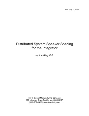
11. The last step is to place the neodymium magnets in the center of the voice coil. Begin bygluing a small piece of cardboard to the middle of the remaining business card. Thepermanent magnets will sit on top of this piece of cardboard in order to decrease thedistance between the voice coil and the magnets. You may need more than one piece ofcardboard for this purpose. Ideally the wire of the voice coil will completely wraparound the permanent magnets when everything is assembled.12. With your cardboard glued in place tape one of the permanent magnets to the top ofthe cardboard pieces. The remaining magnets can then be placed on top of the first; themagnetic force should be sufficient to hold them in place in a neat stack.13. Lifting the paper plate diaphragm up slightly, slide the permanent magnets in placebeneath the voice coil, taping the supporting business card to the cardboard base tokeep everything in place.14. To play a signal through the speaker you must be able to connect the wires from thevoice coil to a signal source. Magnet wire is coated with an insulative layer to preventmagnet coils from shorting. This layer of insolation must be removed from the ends ofthe wire in order to make a connection. Sand paper works well to remove the insulation.Remove about an inch of the insulation from each end of the wire connected to thevoice coil.Two pictures of how the finished voice coil and diaphragm should be connected to the cardboard base and permanent magnets.
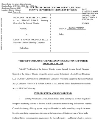
A smart phone connected to pair of headphones connected to a paper speaker.Connect your speaker to a pair of headphones:1. In order to connect your speaker to a pair of headphones, you must get access to the wires thatcarry the signal from the 3.5mm audio jack at one end of the headphones, and one of the smallspeakers at the other end. This can be achieved by either cutting one of the headphone’s wires(a), or by breaking open one of the earbuds to reach the speaker inside (b):a. You can cut off one of the earbuds and strip away the shielding to access the wires. Thesame strategy can be used further down before the two earbuds split. This will give accessto the left, right, and ground wires, of which you will need the ground, and either the leftor the right audio channel, but not both. Pictured below is the result of cutting off one ofthe earbuds. The rubber shielding has been stripped away so you can clearly see thecopper ground wire, and the red colored right audio channel.A pair of headphones with one of theearbuds cut off and the insulationstripped away to expose the signaland ground wires.
b. The other option is to break open one of the earbuds to expose the speaker inside. Thetwo wires connected to the small speaker are the wires you will connect your speaker to.The small speaker may need to be removed if you are having difficulty hearing sound fromyour speaker after you connect it to the headphones.A pair of headphones with theearbud broken open to expose thesmall speaker and wires inside.2. Once you have access to two of the signal wires from the headphones, use your alligator clips toconnect one of the stripped, loose wires from your speaker to the ground wire of the headphones,and the other speaker wire to the exposed audio channel of the headphones. These connectionscan be broken very easily, so it may take a few attempts to get sound from your speaker whenconnecting to it in this way.Alligator clips attached to the signal and ground wires from a stripped pairof headphones3. With your speaker all wired up, connect the 3.5mm audio jack of the headphones to your phoneor other device and play any audio. Your speaker should reproduce the audio, but it may be faint.If you cannot hear anything your wire connections may need to be adjusted, or you may need toincrease the volume of the audio signal.
A mini‐amplifier with the 12V power supply, RCA cable, and alligator clips connected.Connect your speaker to a mini‐amplifier (Optional):1. Connect the 12V power supply and RCA to 3.5mm cable to your amplifier as pictured above. Plugin the 12V power supply.2. Now you will connect your speaker to the amplifier. You may do this either with the alligator clips(a) or by connecting the loose speaker wires directly (b):a. Using the alligator clips, connect one end of each of the clips to either the left or rightaudio channels as in the picture above. You may use either channel, but you must connectboth clips to the same channel. Next, connect the other end of one of the alligator clipsto one of the stripped, loose wires of your speaker. Repeat this step for the remainingalligator clip, and the other wire of your speaker.b. To connect without using the alligator clips, insert one of the stripped, loose wires of yourspeaker into the positive ports of either the left or right audio channels on the back of theamplifier. You may use either audio channel, but both wires must be connected to thesame channel to play sound. Next, insert the remaining stripped, loose wire of yourspeaker into the negative port of the same audio channel as the first wire.3. You can now connect the 3.5mm audio jack to your phone or other audio device, turn on theamplifier, and begin playing sound. The amplifier allows you to adjust the volume, bass, and trebleof your audio signal.
Experimental Procedures:Volume (dB)Number of Magnets Trial One Trial Two Trial Three Average654321Background Noise Level:(dB)Hypothesis:In order to better understand the role that the magnetic field has in making sound emanate from yourspeaker you will change the strength of the magnetic field by adding and removing permanent magnets.Volume data will be collected using Google Science Journal. For consistency perform your experiments ina quiet room using a 1 kHz sound source. A sound with a frequency of 1 kHz is well suited to a paper platespeaker due to the physical properties of the paper plate. You may choose to use a different sound foryour tests, but you should use the same sound for all of your trials in order to accurately compare yourdata. It is not recommended to use music for your tests as the volume will not remain consistent in a songthe way it will in a test tone. You can use the tool at http://onlinetonegenerator.com to generate testtones. During all of your tests your speaker and the device you use to collect your data should remain afixed distance apart. No objects or barriers should be placed between your speaker and the device youuse to take measurements. If you are performing the experiment with your speaker connected to anamplifier, you should not adjust the volume settings in between trials. While collecting data you shouldbe careful not to make any noise as this will affect the data. Detailed instructions for downloading eriments/getting‐started‐with‐sound/.1. Before beginning the experiment record what you hypothesize will happen as the number ofpermanent magnets in your speaker changes.2. Select the sound sensor from the Google Science Journal. Record data in the silent room you willbe taking your measurements in. This data will represent the background noise level of the room.The background noise may create some level of error in your data. Try to reduce the backgroundnoise as much as possible. Record the background noise level.3. Place the recording device a fixed distance away from your speaker. The greater the distancebetween the speaker and recording device the lower the volume the recording device will detect.
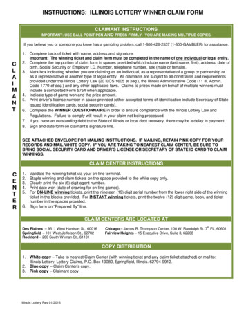
4. Play the test tone on your speaker while recording the data with Google Science Journal. Recordthe result under ‘Trial One’ in the row for the six magnet data in the table above.5. Repeat step four two more times, filling out row six of the table, then average your three trialsand record the average in the indicated column of row six.6. Now remove one of the permanent magnets from your speaker and repeat steps four and five forthe next row of the table.7. Repeat step six until the table is complete. As you remove magnets from the stack, it will benecessary to add additional cardboard spacers to keep the remaining magnets in the center ofthe voice coil.8. Record your data in the graph on the next page. Draw a horizontal line representing thebackground noise level.Follow up Questions: How does the average volume change with number of magnets?Does the data match your hypothesis?Why do you believe the volume changes the way that it does?What effect do you think using an alternative to the paper plate (such as a foam plate, cup, orbowl) will have on the sound quality of your speaker?How do you believe changing the number of turns of wire on the voice coil will affect the volumeof the speaker?How do you think changing the length of the voice coil will affect the speaker?How do you believe the sound will change if you use a larger paper plate? What about a smallerplate?What do you believe will happen if you use different sizes or shapes of magnets?
100908070Volume (dB)605040302010001234Number of Magnets567
Credits:This project was inspired by the Science Buddies project “How Loud Can Speakers Get?”Finio, Ben. "How Loud Can Paper Speakers Get?" Science Buddies, 30 June ‐projects/project‐ideas/Phys p101/physics/paper‐speakers‐loud?from Blog. Accessed 18 July 2018.Which was itself based on this project from Make:Pino, Jose. “Styrofoam Plate Speaker Make:” Make: DIY Projects and Ideas for Makers, Make:Projects, 18 Dec. 2012, . Accessed 18 July2018.Resources for learning about speakers:Harris, Tom. “How Speakers Work.” HowStuffWorks, HowStuffWorks, 2 Feb. 2001,electronics.howstuffworks.com/speaker.htm. Accessed 18 July 2018.Jakeoneal. “How Speakers Make Sound.” Animagraffs, 25 May 2018,animagraffs.com/loudspeaker/. Accessed 18 July 2018.Ampere’s Law:“Ampère's Circuital Law.” Wikipedia, Wikimedia Foundation, 10 July 2018,en.wikipedia.org/wiki/Ampère's circuital law. Accessed 18 July 2018.“Right‐Hand Rule.” Wikipedia, Wikimedia Foundation, 22 July 2018, en.wikipedia.org/wiki/Right‐hand rule. Accessed 23 July 2018.
The last step is to place the neodymium magnets in the center of the voice coil. Begin by gluing a small piece of cardboard to the middle of the remaining business card. The permanent magnets will sit on to