Transcription
NET AFIMSprinkler Systems Design GuideAutomatedWateringSystemsfor Greenhouseand NurserySpinNet SprinklerUSA
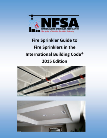
Why Netafim Systems Are BetterDry AreasWet AreaTraditional sprinkler layout spaces the sprinklers“head to head” or at a spacing equal to theradius of the sprinkler throw. For larger areas,the patterns are overlapped creating both wetand dry areas.Traditional “Head to Head” Overlap.The Netafim solution avoidsthe problems of the traditionalsprinkler layout and achievesa high level of uniformitywithin a closely spaced “stripof sprinklers”. By designingwith these “strips” laid outside-by-side, large areas can becovered uniformly.Netafim One Line Solution.VibroNetSprinklerSpinNetSprinklerNetafim Two Line Solution.Low Cost and Fast PaybackUV White PE TubingClean look andcooler watertemperature Payback for a complete system is usually within the firstseason of operation.Drip-less SprinklersSuper FlexUV White PE TubingSoft, flexible4/7mm whitetubingStabilizer WeightKeeps sprinklerplumb The new SpinNet Sprinkler offers drip-less operation - theplants below are not damaged from water dripping off thesprinkler. Check Valve prevents the sprinkler line from draining ontothe plants below after shut-down and provides instantaneouson-off for accurate short cycle watering and misting. Sprinklers hang below the supply pipe, preventing wetting ofthe pipe and dripping onto the plants below.Highly Uniform Watering Increases crop uniformity.Mister, Sprayer,SpinnerDetermineswetted patterns2Check ValvePrevents linedrainage; providesinstantaneouson-offHighly Durable Made from the highest quality plastics with excellentUltra-Violet (UV) resistance. Our reflective white tubing iscompletely opaque to prevent algae growth, UV resistant,and can withstand heat, direct sun and harsh chemicals.Low Maintenance All sprinkler parts can be assembled and disassembled in thegreenhouse without tools.
Design Help for Sprinkler & Fogger SystemsStepVisualize the GreenhouseStepSelect a Sprinkler Head for Watering Applications (go to Step 2b for Misting,12aEvaluate the location of obstacles such as curtains or hanging baskets. Consider aisles and whetherthey can be wetted. Review cultural practices which might impact the height at which the sprinklersshould be placed.Propagation or Cooling Applications)All sprinkler solutions are based on an average sprinkler working pressure of 30 psi and spacingbetween the sprinklers of three feet.Single Bench with VibroNet SprinklersBenchWidth (ft)Spacing BetweenSprinklers (ft)456333Height Above Crop2’ - 3’3’ - 5’VN-BL or VN-GNVN-BL or VN-GNVN-BL or VN-GNVN-BL or VN-GNVN-BL or VN-GNVN-BL or VN-GNFor multiple benches or bays, use 7’, 8’ or 9’ between lines.One Line for Single Bay or Quonset with SpinNet SprinklersBayWidth (ft)Spacing BetweenSprinklers (ft)2’ - 3’Height Above Crop4’ - 5’6’ - R-R-BLBR-Y-GYBR-BR-GNBR-BR-GNBR-BR-GNTwo Line for Single Bay or Quonset with SpinNet SprinklersOrdering GuideBayWidth (ft)Spacing BetweenSprinklers (ft)Spacing BetweenSprinkler Lines (ft)3’Height Above Crop4’ - 5’6’ - onModel -GYR-R-GNBR-BR-GNVibroNet Blue Nozzle w/Check ValveVibroNet Green Nozzle w/Check ValveSpinNet Red Mist Control, Red Body, Blue Spinner w/Check ValveSpinNet Brown Mist Control, Brown Body, Blue Spinner w/Check ValveSpinNet Red Mist Control, Red Body, Grey Spinner w/Check ValveSpinNet Brown Mist Control, Yellow Body, Grey Spinner w/Check ValveSpinNet Red Mist Control, Red Body, Green Spinner w/Check ValveSpinNet Brown Mist Control, Brown Body, Green Spinner w/Check 1600090GL-B9.211.718.423.418.423.418.423.4*Average flow at 32 psi.MistControlBodySpinner3
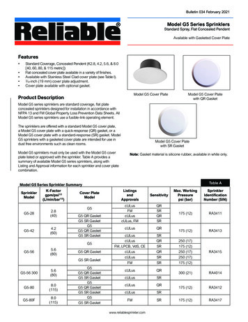
Step2bSelect a Sprinkler Head for Misting,Propagating and Cooling ApplicationsVibroNet SprinklerFor Misting Larger AreasThe VibroNet sprinkler with blue nozzleis used when a light mist is required forwatering, for example when germinatingseeds. Excellent uniformity can be achievedwith sprinkler spacings between 3’ and 5’,with an elevation of 2’ to 5’. The VibroNetsprinkler can be used upright or upsidedown.Model Number0354040L-BDescriptionBlue Nozzle withCheck ValveFlow (GPH)9.2VibroNetSprinkler(Blue Nozzle)CoolNet Pro FoggerThe CoolNet Pro fogger is the bestnozzle for propagation. It creates azone of saturated humidity that is idealfor rooting. Average droplet size is 65micron. Please see the back page forrecommendations on how to use thisproduct for propagation (humidifying)and cooling.4Model NumberDescriptionFlow (GPH)0303420LL-B4 Nozzles with LowPressure Check Valve8.1CoolNet ProFogger(Grey Nozzles)
Step3Select a Sprinkler BaseNetafim offers a selection of three bases to connectthe sprinkler, mister or fogger to the supply pipe.VibroNetSprinkler1/2” Adapter1/2” AdapterUsed for connectionto rigid pipe with 1/2”threaded connections andNetafim sprinklers.HangingAssemblyModel Number03206-BRetrofit AdapterUsed to connectNetafim sprinklers,misters and foggers Model prinklerCoolNet ProFoggerVibroNetMisterSpinNetSprinklerCoolNet ProFoggerHanging Sprinkler, Misteror Fogger AssemblyUsed for connection toPolyethylene (PE) Tubing withNetafim sprinklers, misters andfoggers.Model NumberTube ”18“24”30”36”48”Extension**Used to achieve tube lengths over 48”.5
Step4Size the Sprinkler Supply PipeUse the chart below to select the correct sprinkler supplysize. Low density polyethylene is strongly recommended.Netafim also offers 3/4” or 1” polyethylene tubing withpre-punched holes at 36” spacings.Poly Pipe SizingNozzleColorCoolNet Pro FoggerVibroNet SprinklerSpinNet Sprinkler(Body/Mist Control)Step5AverageFlow (GPH)Length of Sprinkler Supply m UV White PE TubingOffers a cool look, cooler watertemperature, enhanced plant growth.Size the Distributor and MainlineThe remaining piping and system components are sized based upon the maximum flow they willreceive. Use the Flow Per Sprinkler Line chart to determine the flow of a single sprinkler supplypipe for the length of run in your design. If more than one sprinkler line will be operated at once,be sure to multiply the flow by the number of lines when sizing the system pipes and components.Pipe size recommendations are guidelines only. For distributor lines over 40 feet, mainlines over100 feet or when slopes are a factor, please consult a design professional.Flow Per Sprinkler Line (GPM)3‘ Spacingbetween sprinklersAverageFlow(GPH)CoolNet Pro FoggerGrey8.1123467VibroNet ributor PipeSpinNet 433357781010101313131616152020Control HeadComponents(valve, filter &pressure regulator)(Body/Mist Control)Distributor andMainline Pipe SizingPipe SizeMaximum GPM*1/2”3/4”1”1 1/4”1 1/2”2”61017283758* Assumes class 160 PVC and5 fps water velocity.6Length of Sprinkler Supply Pipe(# of Sprinklers)25’50’75’100’ 125’ 150’(9)(17)(25)(34)(42)(50)NozzleColorMainline Pipe
Step6Size the Head Control ComponentsThe components should be sized according to the flow range shown in the Filter, Valve & PressureRegulator Sizing chart. The pipe connecting to the components can be of a different size.Filter and Valve SizingDisc Filter(120 mesh)Unit SizeModel Number26441101761226521103/4” Globe1” Globe1 1/2” Globe2” Globe3/4”1”1 1/2” Super2” Dual 5A47-12025A17-12025A2DL-120Pressure Regulator SizingPressureRegulator(35 psi)*Flow Range(GPM)Unit SizeModel Number5 to 17.611 to 3522 to 703/4”1 1/2”2” PressureRegulatorFLOWElectricValve (AC)MaximumFlow (GPM)Control HeadAssembly Order:*A 35 psi regulator will typically provide the desired average sprinklerpressure after line and component pressure losses.Filter1. Valve2. Filter3. Pressure Regulator*Size of components varybased on flow rate.Sprinkler Supply PipeStep7Starting Up a Systemfor the First TimeThe most important point to rememberwhen starting up a new system is to flushthe mainlines. Debris from construction canotherwise be washed into the sprinklers,causing a plug or improper operation. Toproperly flush a system, first connect all thepipes and assemblies, except the sprinklerswith Check Valves. Next, open the ends ofthe distributor line and the sprinkler supplypipes. Close them off, one by one, startingwith the opening closest to the headcontrol, and proceeding to the most distantopening. Only after complete flushingshould the sprinklers with Check Valves beattached to the assemblies.7
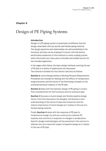
CoolNet Pro FoggerInstallationsHumidification and CoolingInformationGeneral Spacing and Operation for Humidifying and CoolingDistance Between Fogger Units (ft.)Rooting Benches (Propagation)Information3'3'3'18” to 30”3 to 4 Foot Bench - The height of thefogger assembly should be 18” to 30”above the propagation material. Thedistance between the fogger assembliesshould be 3 feet. (Place the lateral abovethe center of a 3 to 4’ bench.)Distance Between Lines (ft.)54-Way Fogger - Pulse (sec.)134-Way Fogger - Interval (sec.)74916.5106.510101013135102030120 150355 345 In order to maximize the cooling effect, exhaust fans arerecommended to exchange the air about 20 times per hour. These recommendations are general and should be applied inaccordance with local conditions and limitations. Duration of pulse and interval is to be fine-tuned according tolocal conditions; the timing provided is just a starting point. For crops that are not sensitive to wetting, the pulse can beprolonged, and/or the interval shortened. Other spacing can certainly be used with foggers; the spacingsabove give some reference points between spacing andoperation intervals.Typical Installation for Humidification or CoolingWide Bench - For wide benches (upto 8’) use two lines of foggers equallydistanced from the center of thebench. For large areas, use one rowof foggers for every 4’ width of areato be fogged.3' to10' Apart3' to 6' Height(generally, higher is better)45 Offset - 4-way crosses should beplaced at 45 angles to one another.36.5 10.55' to15' ApartCooling considerations include: Place foggers as high as possible Avoid spraying against the roof or structure Prevent precipitation by adjusting the cycle timeG22182/14
Ordering Guide Flow* (GPH) Code Description Model Number . is used when a light mist is required for watering, for example when germinating seeds. Excellent uniformity can be achieved with sprinkler spacings between 3’ and 5’, . pipe for the length of run in your design.