Transcription
BURLINGTON ELECTRIC DEPARTMENT (BED)MATERIAL SPECIFICATIONThree Phase, Liquid Filled, Compartmental-Type, Dead Front, Loop FeedPadmounted Transformer (45 through 500 kVA)1) Scope:a) This specification covers the electrical characteristics and mechanical features of three phase, 60 Hz,mineral oil immersed, self-cooled, 65 C rise, padmounted, distribution transformers.b) All transformers shall be in accordance with the latest revision of each referenced industry standard(listed below), except as modified by this specification.ANSI/IEEE C57.12.00ANSI/IEEE C57.12.28ANSI/IEEE C57.12.34ANSI/IEEE C57.12.90ANSI/IEEE C57.91ANSI/IEEE 386Western Underground Committee Guide 2.132) Ratings:a) The kVA rating shall be as specified on the purchase order.b) The nominal high voltage rating and the basic impulse insulation level (BIL) shall be the following:13800 Grd Y/797095 kV BILc) The nominal low voltage rating and the basic impulse insulation level shall be one of the following:208 Grd Y/ 120480 Grd Y/ 27730 kV BIL30 kV BIL3) Impedance Voltage:45 - 112.5 kVA150 - 300 kVA500 kVA1.20% - 2.25%1.20% - 2.50%1.50% - 3.00%4) Testing:a) All transformer testing shall comply with ANSI/IEEE C57.12.00 and ANSI/IEEE C57.12.90.b) All transformers shall be tested for no load losses (85 C), total losses (85 C), percent impedance(85 C) and exciting current (100% rated voltage). No load losses shall also be tested at 105% ratedvoltage.c) All transformers shall be subjected to a full wave voltage impulse.d) The manufacturer shall supply verification that the design has passed Short Circuit criteria perANSI/IEEE C57.12.00 and ANSI/IEEE C57.12.90.e) Complete certified test reports, by serial number, shall be delivered to BED with the transformers.Material SpecificationThree Phase, Liquid Filled, Compartmental-Type,Approved:# S0109Dead Front, Loop Feed, Padmounted TransformerDate:Burlington Electric Department(45 through 500 kVA)3/22/2021Page 1 of 5
These reports must either be signed by an authorized individual at the factory, or be accompanied bya cover letter referring to purchase order number and signed by an agent authorized to conducttransformer sales business for the manufacturer.5) Construction:a) The manufacturer shall certify that the transformer and the oil are PCB free. This shall be indicatedon the transformer nameplate.b) The nameplate shall be made of a corrosion resistant material and permanently marked meetingANSI/IEEE C57.12.00. The nameplate shall be located in the low voltage compartment.c) All wye-wye transformers shall have a five-legged core.d) Wye primary-wye secondary connected units shall have the primary neutral connected (bolted)internally to the secondary neutral, which shall in turn be connected to an insulated low voltageterminal externally grounded by a ground strap to the tank front plate.e) All neutral connections shall be through fully insulated bushing(s) grounded to the transformer tankby removable ground strap(s).f) The internal secondary leads shall be permanently identified corresponding to the lead markings onthe nameplate.g) All insulating components, oil, paper, and wire enamel shall be made of thermally upgraded materialswhich are all compatible at today's industry standard 65 degree C temperature rise.h) All insulating paper used as layer insulation in transformer coils shall be bonded type, coated on bothsides with a thermosetting adhesive and properly cured prior to impregnating with oil or the coilsshall be wound with primary conductor containing a thermosetting adhesive that when properly curedwill form an effective bond, both turn to turn and layer to layer.i) The transformer shall have an electrostatically applied (or equivalent process) protective coating. Thecoating shall be resistant to transformer oils and shall withstand a minimum 160 inch-pound impactper ASTM D2794. The coating shall meet or exceed all requirements of ANSI/IEEE C57.12.28. Thecolor shall be olive green, Munsell No.7.0GY3.29/1.5.j) A hand hole (or hand holes) 6.0" x 18.0" minimum, with a bolted cover, shall be provided in the topof the tank to give access to the primary and secondary bushing well leads.k) Lifting lugs for a balanced lift and provisions for jacking shall be included.l) Construction of the unit shall be such that it can be lifted, skidded or slid into place on the padwithout disturbing the high or low voltage cables.m) The overall dimensions of the unit shall be such that it will fit on a BED Standard 1622 concretetransformer pad (see attached).n) The maximum weight of the transformer shall be less than 8,950 pounds.6) Electrical Compartments - General:Material SpecificationThree Phase, Liquid Filled, Compartmental-Type,Approved:# S0109Dead Front, Loop Feed, Padmounted TransformerDate:Burlington Electric Department(45 through 500 kVA)3/22/2021Page 2 of 5
a) Full height, air filled high voltage and low voltage compartments with hinged doors shall be locatedside by side and separated by a rigid steel barrier.b) The electrical compartment shall have a depth of 24” in place of ANSI/IEEE C57.12.34 Figure 12,dimension C of 18”.c) The high voltage compartment shall be on the left when facing the transformer.d) The high voltage compartment shall be accessible only after the door to the low voltage compartmenthas been opened. The high voltage compartment door shall be secured by a stainless steel penta-headbolt fastening device.e) The low voltage compartment door shall be equipped with three point latching and include provisionsfor locking with a single padlock. Compartment security shall include a recessed, stainless steelpenta-head bolt, which is accessible only with the padlock removed.f) The doors shall open to provide a clear working space. The doors, the compartment hood, and the sillshall be removable with minimal effort using standard line tools.7) High Voltage Compartment:a) The high voltage terminations and equipment shall be dead-front and shall conform to all applicableANSI/IEEE and IEEE standards.b) The high voltage compartment design shall comply with Figure 16 of ANSI/IEEE C57.12.34, ratedfor 8.3 kV/14.4 kV.c) Primary bushings shall be a two-piece design with universal bushing wells and load break bushingwell inserts, rated for 8.3 kV/14.4 kV. BED will provide the bushing well inserts.d) Bushing wells shall be externally clamped and field replaceable.e) Bushing well studs shall be field replaceable.f) Provisions for an insulated bushing (parking stand) shall be included for each bushing.g) Six (6) 200 amp universal bushing wells (for loop feed) shall be provided.h) All bushing well inserts shall be supplied by the customer.8) Low Voltage Compartment:a) The low voltage terminal arrangement shall comply with Figure 8(A) or 8(B) of ANSI/IEEEC57.12.34.b) The low voltage bushings shall be molded epoxy (or approved equivalent).c) The secondary terminals shall be externally removable NEMA standard four (4), six (6) or ten (10)hole spades in accordance with Figure 19, of ANSI/IEEE C57.12.34. NEMA standard six (6) and ten(10) hole spades shall be provided with additional support (bracing) against the weight of conductors.The bracing shall not interfere with the use of any of the holes in the spade.9) Over-current Protection:Material SpecificationThree Phase, Liquid Filled, Compartmental-Type,Approved:# S0109Dead Front, Loop Feed, Padmounted TransformerDate:Burlington Electric Department(45 through 500 kVA)3/22/2021Page 3 of 5
a) Loadbreak, BAY-O-NET type, oil immersed fuses shall be provided in series with oil immersed,back-up current limiting fuses. The BAY-O-NET fuse elements shall be externally replaceable witha distribution hot stick. Dual voltage units shall be capable of accepting both fuse sizes.b) The BAY-O-NET fuses shall be current sensing, RTE type 353C, or equal.c) The BAY-O-NET fuse size shall be per Table 5 of Cooper Power Systems publication 240-98.d) The BAY-O-NET fuses and fuse holders must be interchangeable with RTE brand components.e) The BAY-O-NET fuse assembly shall be equipped with a flapper valve to minimize oil spillage whenthe fuse is removed.f) The back-up current limiting fuses shall be RTE type ELSP, or equal.g) The back-up current limiting fuses shall be coordinated with the BAY-O-NET fuses, per Table 5 ofCooper Power Systems publication 240-98 and sized to melt only on internal transformer faults.h) The current limiting fuses shall be connected on the source side of the BAY-O-NET fuses.i) Oil drip shields shall be provided for each fuse holder.10) If a dual voltage primary is specified by BED, the dual voltage switch shall be for de-energized operationonly and shall have each position clearly labeled.11) Taps:a) If specified by BED, full capacity taps shall be provided in accordance with Section 4.3 ofANSI/IEEE C57.12.34. Taps shall be connected to the primary winding.b) The tap changer shall be for de-energized operation only. The tap changer shall be manuallyoperable by means of a rotary dial (or switch) and shall have provisions for padlocking.c) Each tap changer position shall be labeled. The tap setting must be clearly visible upon opening thecabinet door.d) On dual voltage units, the taps will be on the 13800 volt winding.12) Primary loadbreak switches:a) If specified by BED, the transformer will be equipped with a primary loop feed switch and a primaryradial switch.b) Each switch shall be three phase, two position (on/off), rated for 200 amps (continuous andloadbreak) and 15 kV phase to phase. The on and off positions shall be clearly labeled.c) The BAY-O-NET fuse holders shall be in series with the primary radial switch. When open, theprimary radial switch will de-energize the fuses and the transformer windings.13) The transformer shall be equipped with the following accessories:Material SpecificationThree Phase, Liquid Filled, Compartmental-Type,Approved:# S0109Dead Front, Loop Feed, Padmounted TransformerDate:Burlington Electric Department(45 through 500 kVA)3/22/2021Page 4 of 5
a) One inch diameter (minimum) oil fill plug and oil level plug.b) One inch diameter (minimum) drain plug on 45-300 kVA units.c) One inch diameter (minimum) drain valve and sampler in the high voltage compartment on 500 kVAunits.d) Oil level gauge and dial type thermometer on 500 kVA units.e) An automatic pressure relief device designed to re-seal after operating.f) A means of manually venting tank pressure.g) ANSI/IEEE tank grounding provisions in each compartment.14) Information to be provided with quotation:a) Outline drawing of a typical unit, including a one-line diagram of the transformer.b) Average percent positive impedance, X/R, and percent exciting current.c) Average and guaranteed maximum Total Load Losses.d) Average and guaranteed maximum No Load Losses.e) A description of the method used to minimize tank corrosion (design details or type of treatment).f) Warranty information and location of the nearest service shop, owned and operated by themanufacturer, which is capable of repairing all components of the transformer shall be provided.15) Information to be provided with Shipment of Transformer:a) Manufacturer shall provide BED with the final X/R and percent positive impedance.16) Exceptions:Any exceptions to this specification shall be clearly documented when quoting. Exceptions must bespecifically granted in writing by BED. Failure of BED to acknowledge exceptions when placing anorder requires the manufacturer to comply with this specification if the order is accepted. Manufacturershall not provide exception to the transformer impedance specified in part 3 of this specification.17) Approval of final drawings:Manufacturer shall provide BED with final transformer drawings after P.O. is placed. Approval of finaldrawings by BED shall be required.18) BED's loss evaluation formula applies to all bids.19) Failure to meet quoted losses may result in a financial penalty being assessed the manufacturer. Thepenalty will be determined via BED's loss evaluation formula.Material SpecificationThree Phase, Liquid Filled, Compartmental-Type,Approved:# S0109Dead Front, Loop Feed, Padmounted TransformerDate:Burlington Electric Department(45 through 500 kVA)3/22/2021Page 5 of 5
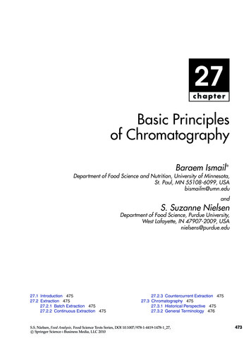
1622WINDOW DIMENSION TABLEkVA757505002500ABNOTESBURLINGTON ELECTRIC DEPT.DISTRIBUTION STANDARDSTHREE Ø TRANSFORMERCONCRETE PADDATE:DWN BY:SCALE:DWG. NO.:APP. BY:SHEETOF
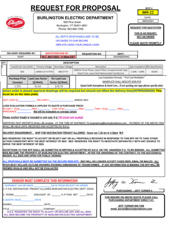
1622NOTESBURLINGTON ELECTRIC DEPT.DISTRIBUTION STANDARDSTHREE Ø TRANSFORMER PADDATE:DWN BY:SCALE:DWG. NO.:APP. BY:SHEETOF
ANSI/IEEE C57.12.00 ANSI/IEEE C57.12.28 ANSI/IEEE C57.12.34 ANSI/IEEE C57.12.90 ANSI/IEEE C57.91 ANSI/IEEE 386 Western Underground Committee Guide 2.13 2) Ratings: a) The kVA rating shall be as specified on the purchase order. b) The nominal high voltage rating and the bas