Transcription
Electrical Tech Note — 106Biosystems & Agricultural Engineering DepartmentMichigan State UniversityMaster Exam Study Guide and Sample Questions1Based on the 2017 NEC, and the Michigan Electrical Code Rules-Part 8The Master electrician examination will ask questions from the following areas. You will need a basicunderstanding of electrical fundamentals as well as how to look up information form the current edition ofthe National Electrical Code. You will also need to obtain a copy of the Part 8 rules to the ConstructionCode Act of Michigan (Act 230 of 1972 as amended), and a copy of the Skilled Trade Regulation Act job(Public Act 407 of 2016 as amended) which governs licensing, permits, and workers conduct on the joband the Electrical Administrative Board General Rules. You can obtain copies of these documents fromthe Office of the Electrical Division of the Bureau of Construction Codes, Michigan Department ofLicensing and Regulatory Affairs or on the web site https://www.michigan.gov/laraWhat Subjects to Study?Grounding and bonding: Determination of electrical system and circuit grounding requirements,methods and location of grounding connections. Choosing proper size grounding conductors, bonding ofenclosures, equipment and interior metal piping systems. Bonding and grounding at service disconnectwhere service conductors are run in parallel. Equipment grounding where conductors are run in parallel inseparate raceways. Grounding where two or more buildings are supplied from a common service.Branch circuits, wire connections and devices: Knowledge of circuit classifications, ratings,design and use requirements. Knowledge and calculation of branch circuit loads. Application of coderules covering electrical outlets and devices, including wiring connectors and methods. Determination ofminimum number of general illumination branch circuits for dwellings. Determination of minimum numberof lighting and receptacle branch circuits for commercial buildings.Conductors: Determination of ampacity, type of insulation, usage requirements, methods ofinstallation, protection, support and termination. Includes calculation of voltage drop and derating. Beable to size conductors for a circuit where the calculated load and rating of overcurrent device is knownand where there are more than three conductors in the raceway. Be able to determine the number ofcurrent carrying conductors in a raceway for derating purposes. Determination of minimum conductor sizefor a service or feeder when the conductors are run as parallel sets.General knowledge of electrical trade: Terminology and practical calculations such as powerfactor, voltage and current ratings of equipment. Be able to calculate the power drawn by an electricmotor as well as the efficiency of the motor.Motors and control of motors and equipment: Knowledge of code rules governing installations ofmotors and controls. Includes calculations for motor feeder and branch circuits, short-circuit, ground-fault,and overload protection, and disconnecting means. Knowledge of all control circuits and motor typesapplication and usage. Be able to read a basic control ladder diagram including the controls for a twospeed motor control or a reversing motor control. Determination of proper size of primary conductors andovercurrent device, and proper size secondary conductors for a wound-rotor motor.General use equipment: Knowledge of code rules covering appliances, heating and airconditioning equipment, generators, transformers, and similar equipment. Be able to determine theprimary and secondary full load current of a transformer. Be able to size the overcurrent protection for atransformer. Determination of minimum demand load for an electric range.1This study guide was developed by Jonathan R Althouse, Master electrician and Instructor and Truman C. Surbrook, Ph.D., P.E., Masterelectrician and Professor: Biosystems & Agricultural Engineering Department, Michigan State University, East Lansing, MI 48824-1323. For a copy ofthis study guide and other educational papers, visit the web site at: https://www.egr.msu.edu/bae/etMSU is an affirmative-action, equal-opportunity institution.Copyright 2019. Biosystems & Agricultural Engineering Department, Michigan State University, East Lansing, MI 48824-1323. All rights reserved
Electrical Tech Note — 106Page 2Services and feeders: Knowledge of code rules covering services. Calculation of demand load fordwelling service and small commercial building service. Determination of proper size of conductors andovercurrent device for a service or feeder given the calculated load. Determination of the maximumunbalance load for a service or feeder. Knowledge of the determination of the demand load for amultifamily dwelling including ranges and other electric appliances.Overcurrent protection: Knowledge of application of fuses, circuit breakers and all types ofprotective devices for conductors and equipment. Determination of minimum size conductor tapped froma feeder for a specific load.Raceways: Knowledge of all types of raceways and their uses. Determining proper size, conductorfill, support and methods of installation. Determine the minimum size conduit or tubing required when theconductors are of different types and sizes. Know the basic rules of installation of cable trays. Determinethe amount of expansion or contraction of rigid nonmetallic conduit with a change in temperature.Special occupancies and equipment: Knowledge of code rules as they apply to hazardouslocations, health care facilities, assembly occupancies, and similar locations including gasoline dispensingstations. Includes code rules for installation of signs, welders, industrial machinery, swimming pools, andother special equipment. Determination of conductor size and overcurrent protection for capacitors.Boxes, cabinets, panelboards, and non-raceway enclosures: Application of proper type, use andsupport of boxes and cabinets, and similar wiring materials. Includes calculation of proper size and ratingof boxes and enclosures. Be able to determine cubic inch capacity of box containing conductors size 6AWG and smaller. Determination of minimum dimensions of pull boxes for straight and angle pulls forconductors 4 AWG and larger.Low voltage circuits and equipment: Knowledge of circuits and equipment characterized by usageand electrical power limitations, which differentiate them from electric light and power circuits. Includesremote-control, signaling, and power limited circuits.Lighting and lamps: Knowledge of all types and applications of luminaires, ratings, requirements foroccupancies, special provisions, clearances, and other requirements. Includes load calculations forlighting.State laws, rules and code amendments: Knowledge of Public Act 407 of 2016, as amended(Skilled Trades Regulation Act), Public Act 230 of 1972, as amended (Construction Code Act) and theElectrical Administrative Board General Rules. Your knowledge of the Part 8 rules to the ConstructionCode Act of Michigan (Act 230 of 1972 as amended) will also be tested. At this time the MichiganResidential Code is not required for the exam.Advanced Electrical Fundamentals and Equations: The following is a brief review ofelectrical terms, principles and equations useful in performing the function of a master electrician. Allmaster electricians should know the following equations. Applications of these equations will bediscussed in the following pages. Also refer to the Journey Electrician Study Guide for additionaldiscussion of fundamentals that should be known prior to taking a master electrician examination.Ohm’s Law:Voltage Current ResistanceE I RVoltage Drop: If the objective is to figure voltage drop for a circuit there are two wires for a single-phasecircuit and three wires for a 3-phase circuit. If the total voltage drop for the circuit is needed, use thefollowing equations where the resistance of the conductor is looked-up in Table 8 of the Code. The letterR is the resistance of one wire supplying the load, and I is the current in one wire supplying the load.Single-phase:Voltage Drop 2 I RThree-phase:Voltage Drop 1.73 I RThe resistance of a conductor is simply the resistivity (K) times the length of conductor (L) divided bythe cross-sectional area (A) of the conductor where cross-sectional area is in circular mils (cmil) and canbe found in Table 8 of the Code. Recommended values of K to use in a calculation of resistance of aconductor at typical operating temperatures are as follows:K 12 for copperK 19 for aluminum. (At approximately 50oC)Copyright 2019. Biosystems & Agricultural Engineering Department, Michigan State University, East Lansing, MI 48824-1323. All rights reserved
Electrical Tech Note — 106Page 3Single-phase: Voltage Drop Three-phase:2 K I L------------------------------AVoltage Drop 1.73 K I L----------------------------------AIf the purpose is to size the conductor given the type of conductor, length of circuit (L), current flow(I), and allowable voltage drop (%), the following equations can be used to determine the minimum size ofconductor. The voltage drop is actually the percentage drop to be allowed times the circuit voltage.Convert % to a decimal before using in the equation. Go to Table 8 in the Code to look up the minimumwire size. (Use value of K from bottom of previous page)Single-phase:A 2 K I L------------------------------%Decimal ECircuitThree-phase:A 1.73 K I L----------------------------------%Decimal ECircuitPower Equation: This equation is useful to determine the power drawn by a load such as an electricmotor. If the voltage, current, and power draw of a load is measured, it is easy to calculate the powerfactor of the load.Watts Amps Voltage power factorSingle-phase:P I E pfThree-phase:P 1.73 I E pfPower factorWatts -----------------------Volts Amps(Single-phase)Power factorWatts -----------------------------------1.73 Volts Amps(3-phase)Efficiency: The efficiency of a device is the output divided by the input. In the case of an electrical loadthis is the power produced divided by the power drawn. In the case of an electric motor the powerdeveloped is likely in horsepower, while the power drawn is found by measuring the volts, amps, andpower factor, then determining the power drawn. Or the power drawn could be measured directly. In anyevent it will be necessary to either convert watts to horsepower or vice versa. Memorize the horsepowerto watts conversion which is 746 watts per horsepower.Horsepower 746Efficiency --------------------------------I E pf(Single-phase)Horsepower 746Efficiency -----------------------------------1.73 I E pf(3-phase)Copyright 2019. Biosystems & Agricultural Engineering Department, Michigan State University, East Lansing, MI 48824-1323. All rights reserved
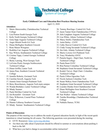
Electrical Tech Note — 106Page 4Current from Watts or kVA: The load in watts may be given such as the rating of a water heater, range,or resistance heater. If the current is not given it is simply calculated by use of the power equation. Forresistance type loads, power factor is assumed to be 1.0 and the current is the wattage divided by thevoltage for single-phase equipment. The following equations can be used to determine the current drawnby resistance loads.(Single-phase)(3-phase)Equipment such as transformers are rated in kVA and it is necessary to determine the full-loadcurrent before sizing conductors and overcurrent devices. The same previous two equations are usedexcept the kVA is multiplied by one thousand to convert to volt-amperes.(Single-phase)(3-phase)Grounding and Bonding: System grounding and equipment grounding serve different purposes and areboth covered in Article 250 of the NEC. When sizing the conductors for system grounding and forequipment grounding make sure you use the correct tables in the Code.Service Grounding and Bonding: The master electrician must be able to determine the minimumpermitted size of grounding and bonding conductors for a service disconnecting means even when theservice conductors are run to the disconnect as parallel sets as illustrated in the following example:Example: A 1600 ampere service is supplied with four sets of 500 kcmil copper conductors. Thegrounding electrode is an underground metal water pipe and a set of driven ground rods. Theservice conductors are run in separate rigid metal conduits. The grounded conductor is bonded tothe disconnect enclosure with a copper conductor as illustrated in Figure 1. Determine the followingfor the service:(1) Minimum size copper grounding electrode conductor to the water pipe.(2) Minimum size copper grounding electrode conductor to the ground rods.(3) Minimum size copper main bonding jumper permitted in the disconnect enclosure.(4) Minimum size of a single copper supply-side bonding jumper to the metal serviceraceways.Figure 1 The service consists of four parallel sets of 500 kcmil copper service entranceconductors, and the common service conductor is grounded to a metal underground water pipeand a set of driven ground rods.Copyright 2019. Biosystems & Agricultural Engineering Department, Michigan State University, East Lansing, MI 48824-1323. All rights reserved
Electrical Tech Note — 106Page 5Answer: (1) The size of copper grounding electrode conductor from the neutral terminal to the waterpipe according to the rule in 250.66 sets the minimum size at the value found in Table 250.66. Note1 of Table 250.66, in the case of multiple sets of service conductors, specifies the total crosssectional area of each phase as 4 times 500 kcmil or 2000 kcmil. From Table 250.66, the minimumsize grounding electrode conductor to the water pipe is size 3/0 AWG copper.(2) The conductor to the set of ground rods is not required to be larger than size 6 AWG copperas stated in 250.66(A). It is permitted to run the conductor from the grounding point in thedisconnect, or simply continue on from the metal water pipe to the set of ground rods.(3) In many cases the manufacturer of the equipment provides a means of bonding thedisconnect enclosure to the grounded service conductor. In this case it will be assumed that acopper conductor will be used as the main bonding jumper. Section 250.28(D)(1) requires theminimum size to be determined using Table 250.102(C)(1) unless the conductor size exceeds thesize listed in the table. In this case Note 1 requires the minimum size to be determined by multiplyingthe largest service conductor cross-sectional area by 0.125 (12½%). For this example, the mainbonding jumper will be 0.125 times 2000 kcmil which is 250 kcmil.(4) It is required to bond the metal service raceways to the grounded service conductor. This iscalled a supply-side bonding jumper. The minimum size conductor, according to the last sentence of250.102(C)(2), is required to be not smaller than specified in Table 250.102(C)(1) and Note 1 basedupon the combined area of the parallel sets of service conductors. If the conductors are larger thanthe maximum size listed in Table 250.102(C)(1), the minimum size is based upon 0.125 times(12½%) the cross-sectional area of the largest equivalent area of the parallel service conductors ofone phase. For this example the minimum size single copper supply-side bonding jumper to bond allfour service conductor raceways, as shown in Figure 1, is 250 kcmil copper.Equipment Grounding: When equipment grounding is accomplished by means of an equipmentgrounding conductor, the size is determined from Table 250.122. For a branch circuit or a feeder, theconductor is protected by fuses or a circuit breaker. The size of equipment grounding conductor is basedupon the rating of the fuse or circuit breaker. For the following example, look up 150 amperes in Table250.122. It will be necessary to go to 200 amperes because 100 amperes is too small.Example: A set of size 1/0 AWG copper feeder conductors with 75oC insulation and terminations isprotected with a 150 ampere circuit breaker. The conductors are run in nonmetallic raceway and anequipment grounding conductor is required. The minimum size copper equipment groundingconductor for this circuit is determined from Table 250.122 and is:A. 12 AWG copper.D.6 AWG copper.B. 10 AWG copper.E.6 AWG aluminum.C.8 AWG copper.When branch circuit or feeder conductors are run in parallel as permitted by 310.10(H) with each setof conductors in a separate nonmetallic raceway, an equipment grounding conductor is required to be runwith the circuit conductors in each raceway, 250.122(F)(1)(b). The equipment grounding conductor ineach raceway is required to be sized based upon the rating of the circuit or feeder overcurrent device asstated in the last sentence of 250.122(F). For the following example, look up the 300 ampere overcurrentdevice in Table 250.122. A size 4 AWG equipment grounding conductor is required to be run in each ofthe parallel raceways.Example: A feeder is run from one panel to another as two parallel sets of size 1/0 AWG copperconductors with 75oC insulation and terminations in separate rigid nonmetallic raceways. The feederis protected by a set of 300 ampere fuses. If the equipment grounding conductor run with eachparallel set of conductors is copper, the minimum size permitted is:A. 8 AWG.D. 3 AWG.B. 6 AWG.E. 2 AWGC. 4 AWG.Voltage Drop Adjustment: The size of a circuit conductor will affect the amount of current that will flow ifthere is a short circuit or a ground fault. Therefore, if the conductor size is increased to compensate forvoltage drop or oversized for any reason more than the minimum required, it will be necessary accordingto 250.122(B) to make a proportional increase in size of equipment grounding conductor, if one is requiredCopyright 2019. Biosystems & Agricultural Engineering Department, Michigan State University, East Lansing, MI 48824-1323. All rights reserved
Electrical Tech Note — 106Page 6to be run with the circuit conductors. Examine the following example where the feeder conductor size isincreased from size 3 AWG to size 2 AWG.Example: A feeder requires size 3 AWG copper conductors run in rigid nonmetallic conduit ifprotected with a 100 ampere circuit breaker. The length of run is long, and to prevent excessivevoltage drop, the circuit conductor is increased to size 2 AWG rather than using size 3 AWG which isthe minimum size permitted. If a copper equipment grounding conductor is installed in the rigidnonmetallic conduit, the minimum size permitted is:A. 8 AWG.C. 4 AWG.E. 2 AWG.B. 6 AWG.D. 3 AWG.Answer: First look up the minimum size equipment grounding conductor required for the circuitusing Table 250.122. The minimum size required is 8 AWG copper. Look up the circular mil area ofthe ungrounded conductors from Table 8, Chapter 9 and divide the largest by the smallest. (size 3AWG is 52,620 circular mils and size 2 AWG is 66,360 cmil) Divide 66,360 by 52,620 to get 1.26.This is the multiplier you will use to adjust the size of equipment grounding conductor. Next look upthe minimum size of equipment grounding conductor required for the circuit. Assuming copper, theminimum is size 8 AWG for a 100 ampere circuit which from Table 8, Chapter 9 has an area of16,510 cmil. Now multiply 16,510 by 1.26 to get 20,803 cmil. The adjusted size of equipmentgrounding conductor must not have an area less than this value. Finally look up the new minimumsize equipment grounding conductor in Table 8, Chapter 9 which is a 6 AWG with an area of 26,240cmil. (From a practical standpoint, in most cases just choose the next size larger equipmentgrounding conductor.)Grounding When Supplying Two or More Buildings: This is a change that started with the 2008 Code.When supplying power from an electrical system with a grounded conductor out of one building and intoanother building on the same property, it is required by 250.32(B) to run a separate equipment groundingconductor in addition to an insulated neutral for all new construction. There is an exception that permitsthe neutral to also serve as the equipment grounding conductor when feeding an existing building. Takethe time to study this section. There may be a question on the exam about this subject. Also read250.32(A) which specifies a grounding electrode to be installed at the main disconnect for a buildingsupplied from elsewhere on the premises.Motor Circuits: The Master exam will test understanding of a single-motor circuit as well as a feedersupplying multiple motors. It is also important to understand some basic motor controls.Single Motor Circuit: The rules for specifying the size of components of a motor branch circuit are foundin Article 430. The conductor is sized according to the rule in 430.22. Look up the full-load current of themotor in either Table 430.248 or Table 430.250, and multiply that current by 1.25. This is the minimumallowable ampacity of the conductors. Generally circuit breakers and terminals in motor circuits are ratedat 75oC, therefore, the 75oC column of Table 310.15(B)(16) can be used. Common 3-phase motors aregenerally design B, design C, or design D and thus according to 110.14(C)(1)(a)(4) it is permitted to usethe 75oC column of Table 310.15(B)(16) provided the conductors have 75oC rated insulation. Look up theconductor size directly from the table. For example, if the motor draws 15.2 amperes, multiply by 1.25 toget 19 amperes. This is a size 14 AWG copper conductor. When sizing the branch-circuit short-circuitand ground fault device, (fuse or circuit breaker), look up the multiplier from Table 430.52. Then multiplythe full-load current by this multiplier and look up the next standard rating overcurrent device in 240.6(A)that is equal to or higher than the ampere value determined. For example, assume time-delay fuses areused and the motor draws 15.2 amperes. Find the multiplier of 1.75 from Table 430.52. The maximumrating overcurrent device permitted for a normal starting motor is 15.2 amperes times 1.75 equals 26.6amperes. Round up to a 30 ampere overcurrent device, 430.52(C)(1) Ex 1. Also know the rules for sizingrunning overcurrent protection from 430.32.Wound-Rotor Motor: A wound-rotor motor is a 3-phase induction motor with windings on the rotorinstead of an aluminum squirrel cage. There are slip rings so the rotor circuit can be run to a remote setof resistors. The rotor circuit is called the secondary of the wound-rotor motor. When the stator fieldwinding is energized with 3-phase power, current is induced into the windings in the rotor. By placingresistance in series with the rotor windings, the inrush current of the motor and speed of acceleration canCopyright 2019. Biosystems & Agricultural Engineering Department, Michigan State University, East Lansing, MI 48824-1323. All rights reserved
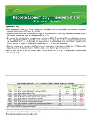
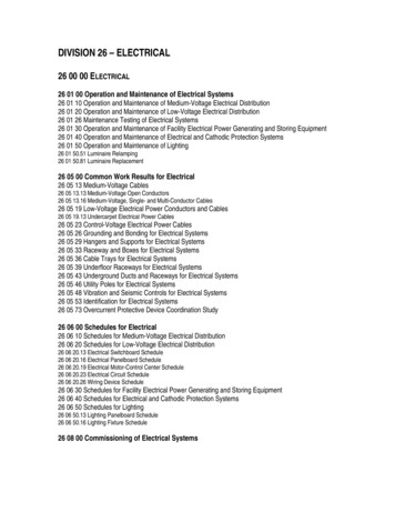
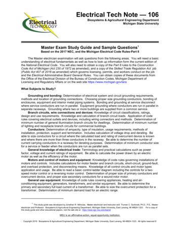
Electrical Tech Note — 106Page 7be controlled to some extent. A typical wound-rotor motor circuit has supply conductors running to acontroller then to the motor. This part of the circuit is sized just like any other single-motor branch circuit.There is often a set of secondary wires running from the motor back to the controller. The full-loadsecondary current must be shown on the motor nameplate and given in the problem. The conductorsfrom the motor back to the controller are sized at 1.25 times the full-load secondary current, 430.23(A).The resistors may be located in an enclosure separate from the controller. If that is the case, thoseconductors will not be carrying the full-load secondary current. The secondary full-load current would thenbe multiplied by the appropriate factor found in Table 430.23(C). Any question would have to give theinformation necessary to use the table. Figure 2 shows a wound-rotor motor circuit.Figure 2. A wound-rotor motor supply circuit is treated like any other single motor branch circuit, butthe secondary circuit conductors are sized according to the rules in 430.23.Feeder Supplying Several Motors: If a feeder conductor supplies several motors, the feeder can besized for that specific motor load. The conductor is not permitted to be smaller than 1.25 times the fullload current of the largest motor plus the full-load current of all other motors according to 430.24. Themaximum permitted rating of motor feeder fuse or circuit breaker is determined using the rule in 430.62.Be careful here. You must first find out which motor circuit supplied by the feeder has the highest ratedfuse or circuit breaker. Take that rating and add to it the full-load current of all other motors. Forexample, assume a feeder supplies three 460 volt, 3-phase motors; one draws 52 amperes, one draws 40amperes and the last draws 34 amperes. Assume each motor circuit is protected by time-delay fuses andthe rating of fuses for the circuits are 100 amperes, 70 amperes, and 45 amperes. The maximum ratingtime-delay fuse permitted for the feeder is 150 amperes. (100 ampere fuse rating plus 40 amperes plus34 amperes equals 174 amperes.) This is a maximum that cannot be exceeded, therefore, it is requiredto round down to 150 amperes. Incidently the minimum permitted conductor size for these motors is 1.25times 52 amperes plus 40 amperes plus 34 amperes which gives 139 amperes which is a size 1/0 AWGcopper wire.If circuit breakers were used for branch-circuit and ground-fault protection for the motors of theprevious example the values would be 150 amperes, 100 amperes, and 90 amperes. The feederconductor would remain size 1/0 AWG copper, however, the feeder short-circuit and ground-faultprotective device would have a rating limit of 200 amperes (150 A 40 A 34 A 224 A, round down to200 A).Motor Control Circuits: It is important to be able to read and understand motor control ladder diagrams.See the Journey Exam Study Guide for the basics of reading ladder diagrams. In addition to the basics,be able to recognize a properly connected two-speed motor control circuit and a reversing motor controlcircuit. A diagram of each is shown in Figure 3 and Figure 4. The primary difference between the twodiagrams is that in Figure 3 it is necessary to push the stop button before the motor will go from highspeed to low speed. Examine the diagram of the control circuit of Figure 3 and Figure 4. Just ahead ofthe solenoid coil note the normally closed set of contacts. These contacts prevent both solenoids frombeing energized at the same time.Copyright 2019. Biosystems & Agricultural Engineering Department, Michigan State University, East Lansing, MI 48824-1323. All rights reserved
Electrical Tech Note — 106Page 8Figure 3. There are three push buttons, one marked stop, one marked high speed, and one markedlow speed. The other high push button is internal. The dotted lines mean the components aremechanically interlocked so they operate at the same time. The two coils are interlocked so one willnot close unless the other is open.Figure 4. There are three push buttons, one marked stop, one marked forward, and onemarked reverse. The dotted lines mean the components are mechanically interlocked sothey operate at the same time. The two coils are interlocked so one will not close unlessthe other is open.Capacitor Conductor Sizing and Overcurrent Protection: Capacitors are frequently a part ofequipment such as a motor variable frequency drive. Unless the drive is opened for maintenance, anelectrician is generally not required to size and install circuit components such as conductors andovercurrent protection. These tasks may be necessary in the case of power factor correction.Capacitor Full-Load Current: Capacitors may be added to a wiring system sometimes for power factorcorrection. The capacitors used for this purpose are generally selected for the proper voltage, and ratedin kilo-VARs (kVARs). It may be necessary to size the conductors for a bank of capacitors as well as theovercurrent protection. For this purpose, treat the problem just like it was a power problem as describedearlier. To determine the full-load current, multiply the kVAR rating of the capacitor by 1000 and divide bythe voltage. If it is a 3-phase capacitor bank, also divide by 1.73. The following equation is for a 3-phasecapacitor bank. For a single-phase capacitor bank omit the 1.73 in the denominator.kVAR 1000Full-load current ------------------------1.73 VoltsCapacitor Conductor Size: Conductors connected to a capacitor bank are sized at 135% of thecapacitor full-load current rather than the typical 125% for other types of circuits, 460.8(A). Afterdetermining the capacitor full-load current, multiply by 1.35 and look up the minimum size in Table310.15(B)(16). Make sure the termination temperature rating and the conductor insulation is known inorder to use the correct column of Table 310.15(B)(16).Example: Determine the size of conductors for a 50 kVAR, 460 volt, 3-phase capacitor bank.Answer: First determine the full-load current of the capacitor bank. In this case, it is a 3-phasebank and the 1.73 must be in the denominator as shown in the above equation.Copyright 2019. Biosystems & Agricultural Engineering Department, Michigan State University, East Lansing, MI 48824-1323. All rights reserved
Electrical Tech Note — 106Page 950 kVAR 1000Full-load current ----------------------------- 63 amperes1.73 460 VNext, size the conductor by multiplying the full-load current by 1.35 and look up the conductor size inTable 310.15(B)(16). The minimum permitted conductor ampacity is 1.35 times 63 amperes which is85 amperes. If conductor insulation and termination temperature are not specified in the problem,then use the 60EC column and find size 3 AWG copper. If the conductors are size 1/0 AWG orlarger, use the 75oC column of Table 310.15(B)(16). There is no specific rule for determining theminimum or maximum rating of the overcurrent device except that it is to be as low as practical. It isa complex process that is performed by
Master Exam Study Guide and Sample Questions1 Based on the 2017 NEC, and the Michigan Electrical Code Rules-Part 8 The Master electrician examination will ask questions from the following areas. You will need a basic understanding of electrical fundamentals as well as how to look up