Transcription
Amateur Extra Class License Study GuideCompiled by; KC3DXSCompiled from; The ARRL Extra Class Manual – Eleventh EditionQuestions for use from 1 July, 2016 – 30 June, 2020This study guide is meant to compliment the ARRL Extra Class Manual, not replace it.1
Chapter 2 – Operating PracticesGeneral OperatingExtra Class HF FrequenciesFrequency SelectionDXing – 2-3E2C08 – The ARRL’s QSL service handles both US-to-DX and DX-to-US QSL’s, But not US-to-UScards because there would be too many and for which regular mail is available.E2C05 – Many DX stations use the services of a QSL manager who confirms contacts and sendsout responding QSL cards for a DX station.DX Windows and Watering HolesE2C06 – Dxing and contests on VHF and UHF bands take place in the “weak signal” allocationsat the low end of the band.Pileup Productivity – 2-42-5E2C10 – If the stations are spread out over a few kilohertz, the DX station is probably workingsplit. Look for the DX station down a few kilohertz or more if the DX station is operating on afrequency unavailable to you, perhaps outside the U.S. band entirely. This practice separatesthe signals of the calling stations from the DX station, reducing interference and improvingefficiency.E2C11 – Give your full call sign or twice (using standard phonetics on phone) and then pause tolisten for the DX station.DXing PropagationE2C12 – By learning how HF propagation works, you know that the MUF between your stationand Europe is dropping. In response, change to a lower frequency.Contesting – 2-62-72
E2C03 – By general agreement contesting does not take place on the 60, 30, 17 and 12 meterbands, giving non-contest operators room during busy weekend events.E2C04 – Contacts via repeaters are usually not allowed, since the goal is to exercise the skill ofthe operators in making contacts without using an intermediate station.Submitting a Contest Log – 2-7E2C01 – You are encouraged to make contacts whether you intend to submit a log to thecontest sponsors or not – no entry is required.E2C07 – The Cabrillo format is a standard for organizing the information in a submitted contestlog so that the sponsor can check and score the QSO’s.Using Spotting Networks – 2-82-9E2C02 – The only way in which spotting networks may not be used is to self-spot. That isannouncing your own call sign and frequency on the spotting networks.Remote Stations – 2-9E2C13 – You must identify your transmissions according to the rules for operation that apply atthe transmitter if they are different from those that apply where the operator is located.Digital Mode Operating – 2-10Packet Radio2-11Packet ClusterE2D04 / E2D05 – These small satellites function as packet bulletin board store-and-forwardsystems. A terrestrial station can send a message through PACSAT by uploading it to thesatellite for another station to download when the satellite is in view.Automatic Packet Reporting SystemE2D07 – The Automatic Packet Reporting System (APRS) is a messaging system that makes useof packet radio. It functions by using the AX.25 Amateur Packet Radio Protocol.E2D08 – APRS stations transmit a beacon containing the stations location, weather conditions,and short text messages. The data is transmitted in an unnumbered information (UI) frame.2-12E2D11 – Position data is sent to the APRS network as latitude and longitude.3
E2A14 – By adding the altitude data from a GPS receiver, a three-dimensional position can beobtained. This type of APRS system is frequently used to track the position of a high-altitudeballoon or rocket in near real-time, aiding in its recovery and linking position with any sensordata being measured.E2D10 – APRS networks can also be used to support public service or emergencycommunications by providing event managers and organizers continuously-updated locationand other information from the APRS equipped station.Amateur Satellites – 2-12Understanding Satellite Orbits2-13E2A03 – One orbit is defined as one complete revolution about the Earth (the orbital period)E2A13 – If the geosynchronous orbit is over the Earth’s equator, the satellite appears to stay inthe same position. This special type of orbit is called geostationary.E2A12 – Kepler’s laws can be expressed mathematically, and if you know the values of a set ofmeasurements of the satellite orbit (called Keplerian Elements), you can calculate the positionof the satellite at any time.Orbital Mechanics – 2-14E2A01 / E2A02 – The descending node is the point where the orbit crosses the equatortraveling from north to south. When the satellite is within range of your location, it is commonto describe the pass as either an ascending pass (traveling from south to north over your area)or a descending pass (traveling from north to south).Faraday Rotation and Spin Modulation2-15E2A10 – You will notice the effect as a fairly rapid, pulsed signal fading. This condition is calledspin modulation.E2A11 – Circularly polarized antennas will minimize the effect, just as they do for Faradayrotation.Transponders – 2-152-16E2A07 – A transponder can be thought of as a multimode repeater. Whatever mode is receivedis retransmitted.4
E2A08 – Because all users must share the power output, continuous-carrier modes such as FMand RTTY generally are not used through amateur satellites and all users should limit theirtransmitting ERP (effective radiated power) to allow as many stations as possible to use thetransponder.E2A04 – The operating mode of a satellite identifies the uplink and downlink frequency bandsthat the satellite is using.E2A05 – The letters in a satellite’s mode designator specify the uplink and downlink frequencyranges.E2A06 – The satellite mode designator U/V specifies that it receives signals on 435MHz –438MHZE2A09 – The terms L band and S band specify the 23cm and 13cm bands.5
Chapter 3 – Rules and RegulationsOperating StandardsFrequency and Emission Privileges3-2E1A05 – The maximum power output allowed on 60 meters is 100 watts PEP effective radiatedpower relative to the gain of a half-wave dipole.E1A06 – The carrier frequency of a CW signal set to comply with FCC rules for 60 meteroperation must be set at the center of the frequency channel.E1A07 – The 60 meter band requires transmission on specific channel, rather than on a range offrequencies.E1A14 – The maximum bandwidth for any transmission on 60 meters is 2.8kHz.3-4 – Displayed Frequency – Managing Your SidebandsE1A01/E1A02 – On USB, it’s prudent to set your carrier frequency no closer that 3kHz belowthe band edge and on LSB, no closer than 3kHz above the band edge.E1A03 – If your carrier is closer than 3kHz to the band edge – say 14.349MHz or 7.126MHz –your sidebands will be outside the band.E1A12 – A typical CW signal has a bandwidth of 50 – 150kHz, so setting the carrier frequencyexactly on the band edge, such as 3500kHz, will result in your signal extending outside the bandeven if your displayed frequency is exactly accurate.3-5 Automatic Message Forwarding3-6E1A08 – If a message violates the FCC rules, the FCC holds the originating station primarilyresponsible.E1A09 – If you become aware that your station inadvertently forwarded a communication thatviolates FCC rules, you should immediately discontinue forwarding that message.RACES OperationE1B09 – Any licensed amateur station may be operated in RACES, as long as the station iscertified by the civil defense organization responsible for the area served.E1B10 – All amateur frequencies are available to stations participating in RACES operation.6
3-7 – Stations aboard Ships or Aircraft (FCC Section 97.11)E1A10 – You must have the radio installation approved by the master of the ship or the pilot incommand of the aircraft.E1A11 – Your FCC license is all that is needed. No other special license or permit is required tooperate aboard ship or aircraft.E1A13 – To operate from international waters (or air space) from a vessel or plane registered inthe U.S. you must have an FCC-issued amateur license or reciprocal operating permit.3-7 – Station RestrictionsOperating Restrictions3-8E1B08 – Where the interference from the amateur station is causing a sufficient amount ofinterference, the FCC can impose quiet periods on the amateur station on the frequencies thatcause interference.E1B01 - FCC Section 97.3(a)(42) defines a “spurious emission” as an emission on frequenciesoutside the necessary bandwidth of a transmission, the level of which may be reduced withouteffecting the information being transmitted.E1B11 – For stations installed in 2003 or later, spurious emissions must be at least 43dB belowthe mean power of the fundamental signal.3-8 – Station Location and Antenna StructuresRestrictions on LocationsE1B02 – If the land on which your station is located has environmental importance, or issignificant in American History, Architecture or culture you may be required to take action asdescribed in FCC Section 97.13(a)E1B04 – If your station will be located within the boundaries of an officially designatedwilderness area, wildlife preserve, or an area listed in the National Register of Historical Places,you may be required to submit an Environmental Assessment to the FCC.E1B03 – If your station is located within 1 mile of an FCC monitoring facility, you must protectthat facility from harmful interference.Restrictions On Antenna Structures3-97
E1B06 – If your antenna is located near a public use airport, then further height limitations mayapply. You must obtain approval from the FAA in such cases.3-10 – Station ControlE1C07 – If you are present at the station and control its operation, that is local control.Remote ControlE1C06 – Operating a station by remote control means that, the control point is no longer at theradio – it’s where the control operator is.E1C01 – The intermediary system that allows you to operate the radio without being in directcontact with it – that’s the control link.E1C08 – If the control link malfunctions, FCC Section 97.213 requires that backup controlequipment should limit continuous transmissions to no more than 3 minutes.3-12 Automatic ControlE1C02 – Defined in FCC Section 97.3(a)(6) as the use of devices and procedures for the controlof a station when it is transmitting so that compliance with the FCC rules is achieved withoutthe control operator being present at the control point.E1C09 – When operating below 30MHz, 29.500MHz – 29.700MHz is the only available range foran automatically controlled repeater.3-12E1C10 – In addition to repeaters, retransmitting the signals of other amateur stations isprohibited only for auxiliary and space stations.E1C05 – Automatically controlled stations may only relay third-party communications as RTTYor data emissions and are never allowed to originate messages.Amateur Satellite ServiceE1D02 – It applies to amateur stations on satellites orbiting the Earth providing Amateur RadioCommunications.E1D04 – Amateur satellite service stations engaging in satellite communications that are on orwithin 50KM of the Earth’s surface are called Earth stations.3-13 Telecommand and TelemetryE1D03 – The process of transmitting communications to a satellite to initiate, modify orterminate the various functions of a space station is called telecommand operations.8
E1D01 – Telemetry is the general term for any one-way transmission of measurements to areceiver located at a distance from the measuring instrument.3-14 – Satellite Licensing and Frequency PrivilegesE1D05 – Any licensed amateur station radio operator may be the control operator of a spacestation – no special license is required.B1D10 – Any amateur station may be a satellite telecommand station subject to the restrictionsof the control operator’s license class.E1D06 – A space station must have incorporated the ability for its transmitter to be turned offby telecommand.E1D07 – A space station may only operate on the 17, 15, 12 and 10 meter bands and onportions of the 40 and 20 meter bands.E1D08/E1D09 – Segments of the 2 meter, 70cm, 23cm, 13cm and some microwave bands arealso available for space station operation.E1D11 – Any amateur station can operate as an Earth station if the privileges of the licenseallow the operator to use the frequencies and modes on which the satellite operates.3-14 – Volunteer Examiner ProgramE1E03 – A Volunteer Exam Coordinator (VEC) is an organization that has entered into anagreement with the FCC to coordinate amateur license exams.3-15 – AccreditationE1E04 – The accreditation process is simply the steps that each VEC takes to ensure their VE’smeet all FCC requirements to serve in the Volunteer Examiner ProgramExam PreparationE1E02 – The set of all the questions available to be asked on an exam is called the questionpool.3-17 – Exam Session AdministrationE1E01 – Every amateur radio license exam session must be coordinated by a VEC, and must beadministered by a VE team consisting of at least three VE’s accredited by the VEC coordinatingthe session.E1E08 – VE’s are prohibited from administering the exams to close relatives as defined by theFCC.9
During The ExamE1E06 – All 3 VE’s are responsible for supervising the exam session and must be present duringthe entire session, observing the candidates to ensure that the session is conducted properly.E1E13 – The VE’s may monitor the station from a different location by using a real time videolink.E1E07 – If any candidate fails to comply with a VE’s instructions during the exam, the VE teamshould immediately terminate that candidate’s exam.E1E05 – A score of 74% is the minimum to pass the exam.E1E12 – If any candidate did not pass all the exam elements needed to complete their licenseupgrade, then the examiners must return their applications to those candidates and informthem of the grades.E1E11 – After grading the exams of those candidates who do pass the exam, the entire VE teammust certify their qualifications for new licensees and that they have complied with the VErequirements on their application forms and issue each a CSCE3-17/3-18E1E09 – If the FCC determines that the VE has fraudulently administered or certified an exam,that VE can lose their amateur station license and have their privileges suspended.3-18E1E10 – The VE team must submit the application forms and test papers for all the candidateswho passed to the coordinating VEC within 10 days of the test session.3-19 - Miscellaneous RulesAuxiliary StationsE1F12 – Control operators of auxiliary stations must hold a Technician, General, Advanced orExtra class license.External Power AmplifiersE1F11 – To receive a grant of certification, an amplifier must satisfy the spurious emissionstandards specified in FCC Section 97.307(d) or (e) when operated at full power or 1500w,whichever is less.3-19E1F03 – Dealers may also sell non-certified amplifiers if they were purchased in used conditionand resold to another amateur for use in their station.10
3-20 - Line A and National Quiet ZonesE1F04 – An imaginary line, called Line A, runs roughly parallel to the south of the U.S. –Canadian border.E1F05 – U.S. stations north of Line A may not transmit on the 420 – 430MHz band.E1B05 – There is an area in Maryland, West Virginia and Virginia surrounding the National RadioAstronomy Observatory. This area is known as the National Radio Quiet Zone.Business and PaymentE1F07 – You can send a message to a business over the air, to order something, as long as youdon’t do it regularly and as part of your normal income making activities.E1C12 – No exception to the non-business rule is made for communications on behalf ofnonprofit organizations.3-20/3-21E1F08 – Another broad prohibition is receiving compensation for communications via AmateurRadio – either being paid directly “for-hire” or in trade of some sort, such as equipment orservices.3-21 Spread Spectrum OperationE1F09 – Spread Spectrum (SS) transmissions must not be used to obscure the meaning on anycommunications.E1F10 – The FCC limits the maximum transmitter power for spread spectrum communicationsto 10 watts.E1F01 – Operation using spread spectrum technologies is restricted to frequencies above222MHz.Non - U.S. Operating AgreementsE1C11 – European Conference of Postal and Telecommunications Administration (CEPT) radioamateur license – allows U.S. amateurs to travel to and operate from most European countriesand their overseas territories without obtaining an additional license or permit.E1C13 – You must carry a copy of FCC Public Notice DA 11-2213-21E1C04 – International Amateur Radio Permit (IARP) – For operation in certain countries ofCentral and South America, the IARP allows U.S. amateurs to operate without seeking a speciallicense or permit to enter and operate from that country.11
3-22E1F02 – Canadian amateurs operating in the U.S. may not transmit SSB below 14.150MHz eventhough they may do so from home.E1F06 – If sufficiently good reasons are provided to the FCC, a Special Temporary Authority(STA) may be granted to provide for experimental amateur communications.12
Chapter 4 – Electrical PrinciplesRadio Mathematics4-2E5C11 – Every point on a rectangular coordinate graph has two coordinates that identify itslocation, X and Y, also written (X,Y)4-4 - Electrical and Magnetic Fields4-5 – Electromagnetic Fields and WavesE3A16 – The changing electric and magnetic fields create electromagnetic waves (i.e. radiowaves) that propagate through space carrying both electric and magnetic energy.E5D08 – The potential energy is shared between the electric and magnetic fields of theelectromagnetic field, just as it is stored in electrostatic and electromagnetic fields.E3A15 – The electric and magnetic fields of the wave are oriented at right angles to each other.4-7 PolarizationE3A17 – It is also possible to generate electromagnetic waves in which the orientation ofsuccessive wave fronts rotates around the direction of travel – both the electric and magneticfields. This is called circular polarization.4-8 – Principles of CircuitsMagnetic Energy Storage4-9E5D06 – The direction of the magnetic field is wrapped around the current at right angles toelectronic current flow and can be determined by the left-hand rule.E5D07 – The strength of the magnetic field depends on the current and is stronger when thecurrent is larger.4-10 RC Circuit Time Constant CalculationsEquation 4.1t RCt – Greek letter tau, represents the time constantR – Total circuit resistance in OhmsC – Capacitance in farads13
Equation 4.2 (for a charging capacitor)V(t) E(1-e(-t/t))V(t) – voltage across the capacitor at time tE – The applied voltageT – Time in seconds since the capacitor began charging or discharginge – The base for natural logarithms, 2.718bolding indicates the e is raised to the power of (-t/t)T – Greek letter tau, the time constant for the circuit, in secondsEquation 4.3 (for a discharging capacitor)V(t) E(e(-t/t))Bolding indicates the e is raised to the power of (-t/t)4-12E5B01 – From the calculations for a charging capacitor we can define the time constant of an RCcircuit as the time it takes to charge the capacitor to 63.2% of the supply voltage.E5B02 – From the calculations for a discharging capacitor we can also define the time constantas the time it takes to discharge the capacitor to 36.8% of its initial voltage.4-13 RL Time Constant CalculationsEquation 4.4t L/REquation 4.5I(t) E/R x(1-e(-t/t))I(t) – Current in Amps at time tE – Applied voltageR – Resistance in Ohmst – Time in seconds after the switch is closedt – Greek letter Tau, time constant for the circuit in seconds.14
4-15 – AC Voltage – Current Relationships in Capacitors4-16E5B09 – Current through a capacitor leads the applied voltage by 90 degrees4-17E5B10 – Voltage applied to an inductor leads the current through it by 90 degrees.4-18 - Writing and Graphing Impedance Phase AngleImpedance values are written in rectangular form as Z R jX where the reactance, X, can bepositive (inductance jX), or negative (capacitive-jX).Example; The impedance 50-j25Ω consists of 50Ω of resistance and 25Ω of capacitive reactance.E5C01 – In rectangular notation, capacitive reactance is represented by a –jX (negative jX)E5C03 - In polar coordinates an inductive reactance is represented by a positive phase angle.E5C04 – In polar coordinates a capacitive reactance is represented by a negative phase angle.E5C06 – In rectangular notation, 50Ω resistance in series with 25Ω capacitive reactance isrepresented as 50-j25E5C09 – When using rectangular coordinates to graph the impedance of a circuit, the horizontalaxis represents the resistive component.E5C10 – When using rectangular coordinates to graph the impedance of a circuit, the verticalaxis represents the reactive component.E5C13 – The rectangular coordinate system is often used to display the resistive, inductiveand/or capacitive reactance components of circuit impedance.E5C12 – When plotting impedance using complex coordinates, any point that falls on thehorizontal axis from ) to 180 degrees is a pure resistance and has no reactive component.4-18E5C02 – Impedance can also be written in polar coordinates as Z Ө, where Z is themagnitude of the impedance and Ө is its phase angle.E5C08 – Impedance in polar coordinates are plotted with the right side of the horizontal axisindicating 0 degrees, the top half of the vertical axis indicating 90 degrees. And so forth.E5C05 – Reactances change with frequency so a Phasor diagram assumes the frequency is thesame for all values.15
E5C07 – Phasors are a type of vector which is why any quantity that has both magnitude anddirection. In the case of phasors, the direction is the angular component.4-18 Combining Resistance and Reactance4-19 – Equation 4.6Z E/I (ER jEX)/I ER/I j(EX/I)4-20 – Admittance and SusceptanceThe reciprocal (or inverse) of resistance is conductance (G)E5B06 – The reciprocal of Impedance (Z) is admittance (Y)E5B12 – The reciprocal of reactance (X) is susceptance (B)E5B13 – The letter B is commonly used to represent susceptance.Remember when taking the reciprocal of an angle, the sign is changed from positive tonegative, or vice versa.E5B03 – When converting the phase angle of a reactance to the phase angle of a susceptance,the sign ( or -) is simply reversed.E5B05 – When the magnitude of a reactance is converted to a susceptance, the magnitude ofthe susceptance is the reciprocal of the magnitude of the reactance. B 1/ X 4-21 – Calculating the Impedances and Phase AngleRule #1; Impedances, resistances, and reactances in series add togetherRule #2; Admittance is the reciprocal of impedance (Y 1/Z), and the susceptance is thereciprocal of reactance (B 1/X). This changes the sign of the angle in polar form: Example1/ Y Ө 1/Y -ӨRule #3; Admittances, conductances and susceptances in parallel add together.Rule #4; Inductive and capacitive reactance in series cancel.Rule #5; 1/j -j16
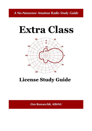
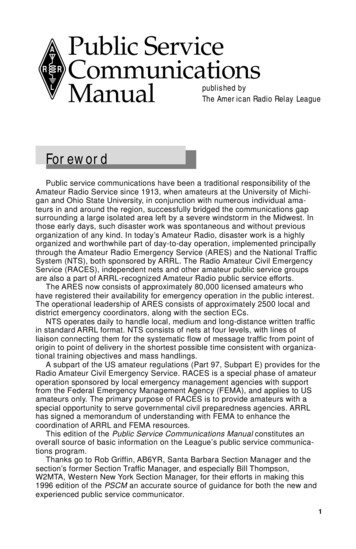
4-22E5C15 – Calculate the impedance of a circuit consisting of a 300Ω resistor in series with an 18µH inductor at 3.505MHz.Step 1 – Calculate the inductor’s reactance.X L 2πFLX L 2x3.14x3.505MHZx18µH 400ΩStep 2 – Use Rule #1 to add the resistance and reactance together.Z 300Ω j400ΩStep 3 – Locate the point of the graph, 300 units along the X axis and 400 units on the Y axis.Answer – Point 317
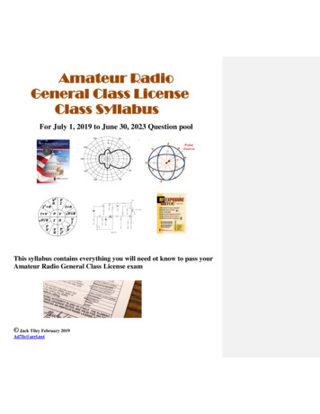
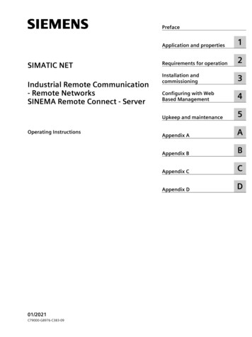
4-23E5C14 – Calculate the impedance of a circuit consisting of a 400Ω in series with a 38 pfcapacitor at 14MHZ.Step 1 - Calculate the capacitor’s reactanceX C 1/2πfcX C 2x3.14x14MHzx38pf -300Ω(Capacitive reactance is assigned a negative value)Step 2 – Use Rule #1 to add the resistance and reactance together.Z 400Ω-j300ΩStep 3 – Locate the point on the graph, 400 units along the horizontal axis and -300 units alongthe Y axis.Answer – Point 418
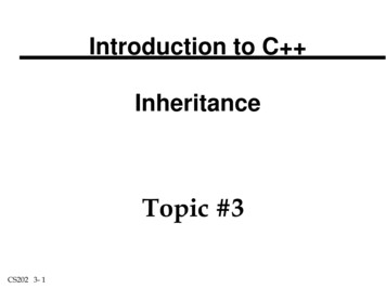
4-23E5C16 – Calculate the impedance of a circuit consisting of a 300Ω resistor in series with a 19pfcapacitor at 21.2MHzStep 1 – Calculate the capacitor’s reactance.XC 1/2πfcXC 2x3.14x19pfx21.2MHzXC -400ΩStep 2 – Use Rule #1 to add the resistance and reactance togetherZ 300Ω-j400ΩStep 3 – Locate the point on the graph 300 units along the X axis and -400 units on the Y axis.Answer – Point 119
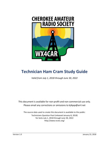
4-24E5C17 – Calculate the impedance of a circuit consisting of a 300Ω resistor in series with a0.64µH inductor and an 85pf capacitor at 24.9MHzStep 1 – Calculate the capacitor’s reactanceX C 1/2πfc 2x3.14x24.9MHzx0.85pf -75ΩStep 2 – Calculate the inductor’s reactanceX L 2πfl 2x3.14x24.9MHzx0.64µH 100ΩStep 3 – Use Rules #1 and #4 to add the resistance and reactances together.Z 300 -j75Ω j100Ω 300 j25ΩStep 4 – Locate the point on the graph that is 300 units along the X axis and 25 units along theY axis.Answer – Point 820
4-24E5B07 – What is the phase angle between voltage and current in a series RLC circuit if XsubC is500Ω, R is 1KΩ and XsubL is 250ΩStep 1 – Use 1000 j250Ω-j500Ω 1000-j250ΩStep 2 - Convert to polar formR square root of (1000) 2 (-250) 2 1031Ө tan-1(-250/1000) -14 degreesZ 1031 -14 degreesΩStep 3 – The phase angle is equal to the angle of the impedance: Ө -14 degrees. Since thephase angle is from voltage to current, the negative angle indicates that voltage lags thecurrent.E5B08 – What is the phase angle between voltage and current in a series RLC circuit ifXC 100Ω, R 100Ω and XL 75ΩStep 1 – Use Rule #1 and #4 to add the resistance and reactanceZ 100 j75Ω –j100Ω 100-j75ΩStep 2 Convert Z to polar formR square root of (100)2 (-25)2 103Ө tan-1(-25/100)Z 103 -14degreesStep 3 The phase angle is equal to the angle of the impedance: Ө -14degrees. Since the phaseangle is from voltage to current, the negative angle indicates that voltage lags the current.21
4-25E5B11 – What is the phase angle between voltage and current in a series RLC circuit ifXC 25Ω, R 100Ω and XL 50ΩStep 1 Use Rules #1 and #4 to add the resistances and reactances together.Z 100-j25 j50 100 j25Step 2 Convert Z to polar formR square root of (100)2 (25)2 103Ө 103 14degreesStep 3 – The phase angle is equal to the angle of impedance: Ө 14degrees. Since phase angleis from voltage to current, the positive angle indicates that voltage leads current.4-25 Reactive Power and Power FactorDefinition of Reactive Power – Electrical power is equal to the RMS values of currentmultiplied by voltage.Equation 4.7 – P IE4-26E5D09 – Only the resistive part of the circuit consumes and dissipates power as heat.E5D14 – The apparent power in an inductor or capacitor is called reactive power ornonproductive, wattles power.Definition and Calculation of Power FactorEquation 4.8For a series circuit – P I2xR (where I is the RMS current)Equation 4.9For a parallel circuit – P E2/R (where E is the RMS voltage)Equation 4.10PF PREAL/PAPPARENTEquation 4.11PREAL PAPPARENT x PFE5D10 – The true power of an AC circuit where the voltage and current are out of phase canbe determined by multiplying the apparent power times the power factor.22
4-27Equation 4.12Power Factor cosӨThe power factor can be calculated from the phase angle by taking the cosine of the phaseangle. PF is positive whether the phase angle is negative or positive.Example 4.12E5D11/E5D15/E5D16 – What is the power factor for an R-L circuit having a phase angle of30degrees? 45degrees? 60degrees?PF for phase angle of 30degrees 0.866PF for phase angle of 45degrees 0.707PF for phase angle of 60degrees 0.50E5D12 – Suppose you have a circuit that draws 4 amperes of current when 100 vac is applied.The power factor for this circuit is 0.2. What is the real power (how many watts areconsumed) for this circuit.Start by calculating apparent power by using Equation 4.7PAPPARENT 100v x 4A 400vaReal power is then calculated using Equation 4.11PREAL 400va x 0.2 80watts4-27/4-28E5D13 – How much power is consumed in a circuit of a 100Ω resistor in series with a 100Ωinductive reactance and drawing 1 ampere of current.Because only the resistance draws power;PREAL I2 x R (1A)2 x 100Ω 100watts4-28E5D17 – How many watts are consumed in a circuit having a power factor of 0.6 if the inputis 200 vac at 5 amperesStep 1 – Find apparent power by using Equation 4.7PsubApparent IE 5A x 200v 1000vaStep 2 – Multiply by the power factor as in Equation 4.11PREAL PAPPARENT x PF 1000 x 0.6 600watts23
E5D18 – How many watts are consumed in a circuit having a power factor of 0.71 if theapparent power is 500vaUse Equation 4.11 to find PsubREALPREAL PAPPARENT x FP 500va x 0.71 355watts4-28Resonant CircuitsE5A02 – Whether the components are connected in series or parallel, we say the circuit isresonant or is at resonance when the inductive reactance is the same as the capacitivereactance.4-29 – Calculation of ResonanceEquation 4.13Fr 1/2π square root of (LC)E5A14 – What frequency should the signal generator in figure 4.25 be tuned to for resonanceif the resistor is 22Ω, the coil is 50mH and the capacitor has a value of 40pF?50µH 50 x 10 to the -640pF 40 x 10 to the -2Fr 1/2x3.14 square root (50x10 to the -6) x (40 x 10 to the -2) 3.56x10 to the 6 3.56MHz4-30E5A16 – Calculating the resonant frequency of a parallel circuit is exactly the same as for aseries circuit. For example; What is the resonant frequency of a parallel RLC circuit if R 33Ω,L 50µH and C 10pF?Fr 1/2π times the square root of (50 x 10 to the -6) x (10 x 10 to the -12) 7.12 x 10 tothe 6 7.12MHzEquation 4.15Stored Energy in Resonant CircuitsE5A01 – The currents that flow back and forth between the inductor and the capacitor toexchange the stored energy are maximum at resonance.24
4-31Impedance of Resonant Circuits versus FrequencyE5A03 – With the voltage across the inductor and capacitor canceling each other, the onlyimpedance presented to the signal generator is that of the resistance, RE5A05 – The magnitude of the current at the input of a series RLC circuit will be at maximumas the circuit goes through resonance.E5A06 – At resonance, the circulating currents will be at maximum, limited
Amateur Extra Class License Study Guide Compiled by; KC3DXS Compiled from; The ARRL Extra Class Manual – Eleventh Edition Questions for use from 1 July, 2016 – 30 June, 2020 This study guide is meant to compliment the