Transcription
The No-Nonsense, Extra Class License Study Guide(for tests given after July 1, 2012)Dan Romanchik KB6NU 2012 Daniel M. Romanchik, KB6NUAll rights reserved. No part of this publication may be reproduced, stored in a retrievalsystem, or transmitted in any form or by any means, electronic, mechanical, recording orotherwise, without the prior written permission of the author.version 1.3, 4/7/2013
Table of ContentsTitle PageGetting your Extra Class licenseE5: Electrical PrinciplesE6: Circuit ComponentsE7: Practical CircuitsE8: Signals and EmissionsE9: Antennas and Transmission LinesE3: Radio Wave PropagationE4: Amateur PracticesE2: Operating ProceduresE0: SafetyE1: Commission’s RulesAbout the Author
Getting your Extra Class licenseI got my Novice ticket way back in 1971. My first callsign was WN8KTZ. Back then, you had toupgrade to General Class within a year or lose your license. I upgraded about eight or nine monthslater. I upgraded to Advanced in 1979 when I was working for an electronics company in SantaClara, CA.This was at the prompting of my boss, who was also a General Class ham. He suggested that wetake a day off, take the train up to the San Francisco FCC office and take the test. It was a beautifulday, we both passed the test, and just had a great time all the way around.I didn’t take the Extra Class test until 2006, almost 30 years later. At first, it was the 20 wpm codetest that put me off. At that point, I wasn’t getting on the air enough to get my speed up to 20 wpm.Later in life, I was afraid that I’d actually fail the written test. Besides, I had a good rejoinderwhenever I was asked why I didn’t have an Extra Class license. I used to joke that I wanted to bethe last living Advanced Class licensee in the U.S.After I started teaching amateur radio classes and writing license study guides, I decided it was hightime to get the Extra. Besides, some of my students had already gotten their Extras, and I found it abit embarassing to have a lower class of license than they had. So, in 2006, I decided it was time tostudy up and take the test.I used the ARRL study guide. It did the job, and the test was actually a little easier than I’danticipated. Even so, I got three wrong. I don’t know that I’d have done any better if there had beena “No-Nonsense” study guide available for me to use. My guess is that it would not have. There arejust so many things that you have to memorize that you’re bound to forget something.At first, I wasn’t planning to produce an Extra Class study guide. There is a lot more material thatyou need to cover for the Extra Class when compared to the Technician Class and General Classthat I knew that writing this study guide would take a long time. The material is a lot more complex,too, and that added to the amount of time it took me to write this book.In the end, though, I knew that I would do it. Every week, I’d get emails from readers asking if orwhen a No-Nonsense Extra Class License Study Guide was going to be available, and I would havefelt that my product lineup was incomplete without it.How to use this manualSimply read through the manual and take some practice tests. You will find the answers to questionsin bold. Question designators, such as “ (E5A07) “ appear at the end of sentences. This is so youcan refer to actual question in the question pool, if you would like to. You can take practice testsonline at QRZ.Com, AA9PW.Com, and several other websites.Good luck and have fun!I hope that you find this study guide useful and that you’ll upgrade to Extra. The Extra Class licensegives you all privileges available to amateur radio operators. This means you get to learn even moreabout our great hobby.If you have any comments, questions, compliments or complaints, I want to hear from you. E-mailme at cwgeek@kb6nu.com. My goal is to continually refine this study guide and to continuallymake it better.73!Dan Romanchik KB6NUcwgeek@kb6nu.com, Twitter: @kb6nu
E5: Electrical PrinciplesE5A - Resonance and Q: characteristics of resonant circuits; series and parallelresonance; Q; half-power bandwidth; phase relationships in reactive circuitsResonance is one of the coolest things in electronics. Resonant circuits are what makes radio, as weknow it, possible.What is resonance? Well, a circuit is said to be resonant when the inductive reactance and capacitivereactance are equal to one another. That is to say, when2πfL 1/2πfCwhere L is the inductance in henries and C is the capacitance in farads.For a given L and a given C, this happens at only one frequency:f 1/2π (LC)This frequency is called the resonant frequency. Resonance in an electrical circuit is the frequencyat which the capacitive reactance equals the inductive reactance.(E5A02)Let's calculate a few resonant frequencies, using questions from the Extra question pool asexamples:The resonant frequency of a series RLC circuit if R is 22 ohms, L is 50 microhenrys and C is 40picofarads is 3.56 MHz. (E5A14)f 1/2π (LC) 1/(6.28 x (50x10-6 x 40x10-12)) 1/(2.8 x 10-7) 3.56 MHzNotice that it really doesn't matter what the value of the resistance is. The resonant frequency wouldbe the same is R 220 ohms or 2.2 Mohms.The resonant frequency of a series RLC circuit if R is 56 ohms, L is 40 microhenrys and C is 200picofarads is 1.78 MHz. (E5A15)f 1/2π (LC) 1/(6.28x (40x10-6 x 200x10-12)) 1/(5.6x10-7) 1.78 MHzThe resonant frequency of a parallel RLC circuit if R is 33 ohms, L is 50 microhenrys and C is 10picofarads is 7.12 MHz. (E5A16)f 1/2π (LC) 1/(6.28x (50x10-6 x 10x10-12)) 1/(1.4x10-7) 7.12 MHzThe resonant frequency of a parallel RLC circuit if R is 47 ohms, L is 25 microhenrys and C is 10picofarads is 10.1 MHz. (E5A17)f 1/2π (LC) 1/(6.28x (25x10-6 x 10x10-12)) 1/(9.9x10-7) 10.1 MHzWhen an inductor and a capacitor are connected in series, the impedance of the series circuit at theresonant frequency is zero because the reactances are equal and opposite at that frequency. If thereis a resistor in the circuit, that resistor alone contributes to the impedance. Therefore, the magnitudeof the impedance of a series RLC circuit at resonance is approximately equal to circuit resistance.(E5A03)The magnitude of the current at the input of a series RLC circuit is at maximum as the frequencygoes through resonance. (E5A05) The reason for this is that neither the capacitor or inductor adds tothe overall circuit impedance at the resonant frequency.When the inductor and capacitor are connected in parallel, the impedances are again equal andopposite to one another at the resonant frequency, but because they are in parallel, the circuit iseffectively an open circuit. Consequently, the magnitude of the impedance of a circuit with a
resistor, an inductor and a capacitor all in parallel, at resonance, is approximately equal to circuitresistance. (E5A04)Because a parallel LC circuit is effectively an open circuit at resonance, the magnitude of thecurrent at the input of a parallel RLC circuit at resonance is at minimum. (E5A07) The magnitudeof the circulating current within the components of a parallel LC circuit at resonance is at amaximum. (E5A06) Resonance can cause the voltage across reactances in series to be larger thanthe voltage applied to them. (E5A01)Another consequence of the inductive and capacitive reactances canceling each other is that there isno phase shift at the resonant frequency. The phase relationship between the current through and thevoltage across a series resonant circuit at resonance is that the voltage and current are in phase.(E5A08) The phase relationship between the current through and the voltage across a parallelresonant circuit at resonance is that the voltage and current are in phase. (E5A09)Ideally, a series resonant circuit would have zero impedance at the resonant frequency and aninfinite impedance at all others. A parallel resonant circuit would have an infinite impedance at theresonant frequency and be zero at all others.Of course, in the real world, resonant circuits don’t act this way. To describe how closely a circuitbehaves like an ideal resonant circuit, we use the quality factor, or Q. Basically, the higher the Q,the more a resonant circuit behaves like an ideal resonant circuit.A parameter of a resonant circuit that is related to Q is the half-power bandwidth. The half-powerbandwidth is the bandwidth over which a series resonant circuit will pass half the power of the inputsignal and over which a parallel resonant circuit will reject half the power of an input signal.We can use the Q of a circuit to calculate the half-power bandwidth:BW f/QLet’s look at some examples:The half-power bandwidth of a parallel resonant circuit that has a resonant frequency of 1.8 MHzand a Q of 95 is 18.9 kHz. (E5A10)BW f/Q 1.8x10⁶/95 18.9 x 10³ 18.9 kHzThe half-power bandwidth of a parallel resonant circuit that has a resonant frequency of 7.1 MHzand a Q of 150 is 47.3 kHz. (E5A11)BW f/Q 7.1 x 10⁶/150 47.3 x 10³ 47.3 kHzWhat is the half-power bandwidth of a parallel resonant circuit that has a resonant frequency of 3.7MHz and a Q of 118 is 31.4 kHz. (E5A12)BW f/Q 3.5 x 10⁶/118 31.4 x 10³ 31.4 kHzThe half-power bandwidth of a parallel resonant circuit that has a resonant frequency of 14.25 MHzand a Q of 187 is 76.2 kHz. (E5A13)BW f/Q 14.25 x 10⁶/187 76.2 x 10³ 76.2 kHz
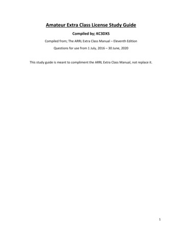
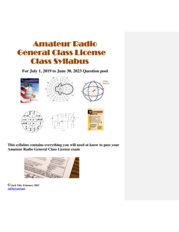
E5B - Time constants and phase relationships: RLC time constants; definition;time constants in RL and RC circuits; phase angle between voltage and current;phase angles of series and parallel circuitsWhen you put a voltage across a capacitor, current will flow into the capacitor and the voltageacross the capacitor will increase until the voltage across it reaches the value of the supply voltage.This is not a linear function. By that I mean that the voltage will increase quite rapidly at first, butthe rate of increase will slow as time goes on.To see how this works, let’s consider the RC time constant. The time constant of an RC circuit isequal to the resistance in the circuit times the capacitance, or simply R x C. For example, the timeconstant of a circuit having two 220-microfarad capacitors and two 1-megohm resistors, all inparallel is 220 seconds. (E5B04)The equivalent resistance of two 1 MΩ resistors in parallel is 500 kΩ. The equivalent capacitance oftwo 220 µF capacitors in parallel is 440 µF. The time constant is RxC 440 x 10-6 x 500 x 103 220 s.One time constant is the term for the time required for the capacitor in an RC circuit to be chargedto 63.2% of the applied voltage. (E5B01) Similarly, one time constant is the term for the time ittakes for a charged capacitor in an RC circuit to discharge to 36.8% of its initial voltage. (E5B02)The capacitor in an RC circuit is discharged to 13.5% of the starting voltage after two timeconstants. (E5B03) Similarly, a capacitor charges to 86.5% of the applied voltage after two timeconstants. After three time constants, a capacitor is charged up to 95% of the applied voltage ordischarged to 5% of the starting voltage.You can use these percentages to answer the questions about how much time it takes for a capacitorto discharge. The key is to figure out what percentage the voltage given is of the starting voltage. Inone case, the starting voltage is 20 V and you must figure out how much time it will take for thecapacitor to discharge to 7.36 V.Well, 7.36 V just happens to be 36.8% of 20 V, so the time required will be one time constant. Onetime constant is R x C, or in this case 0.01 x 10-6 x 2 x 106, or .02 s. So, it takes 0.02 seconds for aninitial charge of 20 V DC to decrease to 7.36 V DC in a 0.01-microfarad capacitor when a 2megohm resistor is connected across it. (E5B05)In the second case, the starting voltage is 800 V and you must calculate the time required for thevoltage across the capacitor to drop to 294 V. Well, fortunately, 294 V / 800 V is again 36.8%, sothe time required will be one time constant.In this circuit, R 1 MΩ and the capacitance 450 µF. R x C 106 x 450 x 10-6 450 s. So, it takes450 seconds for an initial charge of 800 V DC to decrease to 294 V DC in a 450-microfaradcapacitor when a 1-megohm resistor is connected across it. (E5B06)In an AC circuit, with only resistors, the voltage and current are in phase. What that means is thatthe voltage and current change in lock step. When the voltage increases, the current increases.When the voltage decreases, the current decreases.When there are capacitors and inductors in an AC circuit, however, the phase relationship betweenthe voltage and current changes. Specifically, the relationship between the current through acapacitor and the voltage across a capacitor is that the current leads voltage by 90 degrees.(E5B09) We could also say that the voltage lags the current by 90 degrees. See figure below.What that means is that the current through a capacitor increases and decreases before the voltageacross a capacitor increases and decreases. We say that the current leads the voltage by 90 degreesbecause it starts increasing one-quarter of a cycle before the voltage starts increasing.
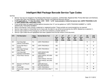
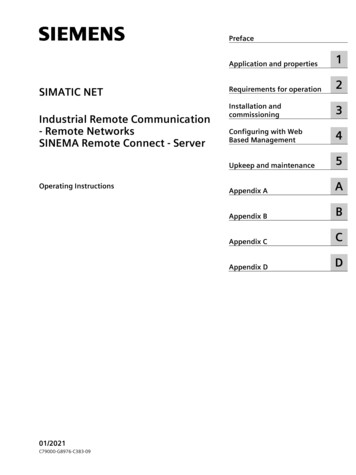
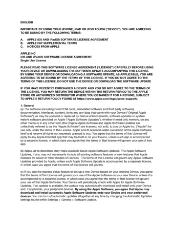
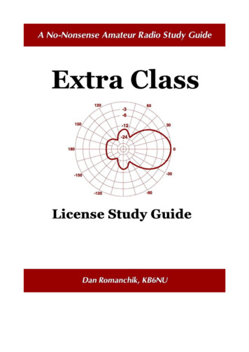
The relationship between the current through an inductor and the voltage across an inductor is thatthe voltage leads current by 90 degrees. (E5B10) We could also say that the current lags thevoltage. See figure below.What that means is that the voltage across an inductor increases and decreases before the currentthrough the inductor increases and decreases. We say that the voltage leads the voltage by 90degrees because it starts increasing one-quarter of a cycle before the current starts increasing.When there are resistors as well as a capacitor or inductor or both in a circuit, the relationship is alittle more complicated. Let’s look at what happens in the series RLC circuit shown below.In this circuit, there is resistance, capacitive reactance, and inductive reactance. The reactancessubtract from one another. If the capacitive reactance is greater than the inductive reactance, the netreactance will be capacitive. If the inductive reactance is greater than the capacitive reactance, thenet reactance will be inductive.The resistance and the reactance add to one another, but they add vectorially. The reason for this is
that the reactance will be 90 degrees out of phase with the resistance. This is shown in the figurebelow.The magnitude of the impedance, Z, will be equal to (R2 X2) and the tangent of the phase anglewill be equal to X/R. Let’s see how this works in several examples.If XC is 500 ohms, R is 1 kilohm, and XL is 250 ohms, the phase angle between the voltage acrossand the current through the series RLC circuit is 14.0 degrees with the voltage lagging thecurrent. (E5B07) Here’s how to calculate that:X XC - XL 250 Ω (capacitive)phase angle tan-1 (250/1000) 14 degrees.and because the reactance is capacitive, the voltage will lag the current.If XC is 100 ohms, R is 100 ohms, and XL is 75 ohms, the phase angle between the voltage acrossand the current through the series RLC circuit is 14 degrees with the voltage lagging the current.(E5B08) Here’s the calculation:X XC - XL 25 Ω (capacitive)phase angle tan-1 (25/100) 14 degrees.and because the reactance is capacitive, the voltage lags the current.If XC is 25 ohms, R is 100 ohms, and XL is 50 ohms, the phase angle between the voltage across andthe current through the series RLC circuit is 14 degrees with the voltage leading the current.(E5B11) Here’s the calculation:X XL - XC 25 Ω (inductive)phase angle tan-1 (25/100) 14 degrees.and because the reactance is inductive, the voltage leads the current.If XC is 75 ohms, R is 100 ohms, and XL is 50 ohms, the phase angle between the voltage across andthe current through the series RLC circuit is 14 degrees with the voltage lagging the current.
(E5B12) Here’s the calculation:X XC - XL 25 Ω (capacitive)phase angle tan-1 (25/100) 14 degrees.and because the reactance is capacitive, the voltage lags the current.If XC is 250 ohms, R is 1 kiloohm, and XL is 500 ohms, the phase angle between the voltage acrossand the current through the series RLC circuit is 14 degrees with the voltage leading the current.(E5B13) Here’s the calculation:X XL - XC 250 Ω (inductive)phase angle tan-1 (250/1000) 14 degrees.and because the reactance is inductive, the voltage leads the current.
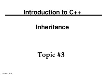
E5C - Impedance plots and coordinate systems: plotting impedances in polarcoordinates; rectangular coordinatesMost often when we plot values on a graph, we use the rectangular, or Cartesian, coordinate system.The two numbers that are used to define a point on a graph using rectangular coordinates are thecoordinate values along the horizontal and vertical axes. (E5C11) In the graph above, point P isat x,y. Rectangular coordinates are often used to display the resistive, inductive, and/or capacitivereactance components of an impedance. (E5C13)When thinking about how capacitive reactances, inductive reactances, and resistance combine, it’suseful to think in terms of polar coordinates. Polar coordinates are often used to display the phaseangle of a circuit containing resistance, inductive and/or capacitive reactance. (E5C14) In a polarcoordinate system, each point on the graph has two values, a magnitude (shown by r in the figureabove) and an angle (shown by θ in the figure above).When using rectangular coordinates to graph the impedance of a circuit, the vertical axis representsthe reactive component. (E5C10) To figure out the impedance of a circuit, you first plot theinductive reactance on the positive y-axis and the capacitive reactance on the negative y-axis. Thenet reactance, X, will be the sum of the two reactances.When using rectangular coordinates to graph the impedance of a circuit, the horizontal axisrepresents the resistive component. (E5C09) After you’ve computed the net reactance, you plot theresistance on the x-axis and compute the magnitude of the impedance, shown by r in the graphabove. If you consider that r is the third side of a right triangle made up of the sides r, x, and y, r isequal to the square root of x2 and y2.Let’s take a look at an example. In polar coordinates, is the impedance of a network consisting of a100-ohm-reactance inductor in series with a 100-ohm resistor is 141 ohms at an angle of 45degrees. (E5C01) In this example, x 100 and y 100, sor (X R ) (1002 1002) (20000) 141 ohms.22The cosine of the phase angle θ is equal to x/r, or 100/141, or .707. If you look up this value in atable of cosines, you’ll find that the angle is 45 degrees.Here’s another thing to notice. When the value of the reactance is equal to the value of theresistance, the angle will be either 45 degrees or -45 degrees, depending on whether the netreactance is inductive or capacitive.
Now, let’s look at an example with both inductive and capacitive reactance. In polar coordinates, theimpedance of a network consisting of a 100-ohm-reactance inductor, a 100-ohm-reactancecapacitor, and a 100-ohm resistor, all connected in series is 100 ohms at an angle of 0 degrees.(E5C02) In this case, the inductive reactance and the capacitive reactance are the same, meaningthat there is no net reactance. If you plot the impedance of a circuit using the rectangular coordinatesystem and find the impedance point falls on the right side of the graph on the horizontal axis, youknow that the circuit impedance is equivalent to a pure resistance. (E5C12)Here’s an example with unequal inductive and capacitive reactances. In polar coordinates, theimpedance of a network consisting of a 300-ohm-reactance capacitor, a 600-ohm-reactanceinductor, and a 400-ohm resistor, all connected in series is 500 ohms at an angle of 37 degrees.(E5C03) Here’s how we got that result:X 600 - 300 300 ohmsr (X R ) (3002 4002) (250000) 500 ohms22θ cos-1(x/r) cos-1(400/500) 37 degreesHere are some more examples. I’ll leave the solutions up to you: In polar coordinates, the impedance of a network consisting of a 400-ohm-reactancecapacitor in series with a 300-ohm resistor is 500 ohms at an angle of -53.1 degrees.(E5C04) In polar coordinates, the impedance of a network consisting of a 400-ohm-reactance inductorin parallel with a 300-ohm resistor is 240 ohms at an angle of 36.9 degrees. (E5C05) In polar coordinates, the impedance of a network consisting of a 100-ohm-reactancecapacitor in series with a 100-ohm resistor is 141 ohms at an angle of -45 degrees. (E5C06) In polar coordinates, the impedance of a network comprised of a 100-ohm-reactancecapacitor in parallel with a 100-ohm resistor is 71 ohms at an angle of -45 degrees.(E5C07) In polar coordinates, what is the impedance of a network comprised of a 300-ohm-reactanceinductor in series with a 400-ohm resistor is 500 ohms at an angle of 53 degrees. (E5C08) In polar coordinates, the impedance of a series circuit consisting of a resistance of 4 ohms,an inductive reactance of 4 ohms, and a capacitive reactance of 1 ohm is 5 ohms at an angleof 37 degrees. (E5C18)Sometimes, we use what are calling “imaginary” numbers to represent reactance. An inductivereactance of 100 ohms would be denoted as j100 ohms. An capacitive reactance of 100 ohms wouldbe denoted as -j100 ohms. The imaginary value j is plotted along the y-axis. Consequently, in polarcoordinates, the impedance of a circuit of 100 -j100 ohms impedance is 141 ohms at an angle of-45 degrees. (E5C15)In rectangular coordinates, the impedance of a network consisting of a 10-microhenry inductor inseries with a 40-ohm resistor at 500 MHz is 40 j31,400. (E5C22) The imaginary value iscalculated using the formula for inductive reactance:X 2πfL 2 x 3.14 x 500,000,000 x .000010 31,400Because this reactance is inductive, the imaginary value is positive.Admittance is the inverse of impedance. So, in polar coordinates, the impedance of a circuit that hasan admittance of 7.09 millisiemens at 45 degrees is 141 ohms at an angle of -45 degrees. (E5C16)You calculate it this way:
Z 1/7.09x10-3 141 ohmsThe angle is the mirror image about the x axis:θ 0 - -45 degrees 45 degreesThe resistive value is then Z cos 45 degrees 141 1 141 ohmsLet’s look at another example. In rectangular coordinates, the impedance of a circuit that has anadmittance of 5 millisiemens at -30 degrees is 173 j100 ohms. (E5C17) Z 1/5x10-3 200 ohmsθ 0 - -30 degrees 30 degreesR Z cos 30 degrees 200 .866 173 ohmsX (the reactance part of the impedance) Z sin 30 degrees 200 .5 j100Now, let’s take a look at some actual circuits.On Figure E5-2, the point that best represents the impedance of a series circuit consisting of a 400ohm resistor and a 38 picofarad capacitor at 14 MHz is Point 4. (E5C19) Right off the bat, weknow that the only choices are really Points 2, 4, and 6 because the resistance is 400 ohms. Next,we calculate the capacitive reactance:XC 1/2πfC 1/(2 3.14 14x106 38 10-12) 300 ohmsBecause the reactance is capacitive, it’s plotted as a negative value.On Figure E5-2, the point that best represents the impedance of a series circuit consisting of a 300ohm resistor and an 18 microhenry inductor at 3.505 MHz is Point 3. (E5C20) The resistance is 300ohms and the reactance is:
XL 2πfL 2 3.14 3.505x10⁶ 18 10-6) 400 ohmsAnd, since the reactance is inductive, it’s plotted as a postive value.On Figure E5-2, the point that best represents the impedance of a series circuit consisting of a 300ohm resistor and a 19 picofarad capacitor at 21.200 MHz is Point 1. (E5C21) The resistance is 300ohms, and the reactance is:XC 1/2πfC 1/(2 3.14 21.2x10⁶ 19 10-12) 400 ohmsBecause the reactance is capacitive, it’s plotted as a negative value.On Figure E5-2, the point that best represents the impedance of a series circuit consisting of a 300ohm resistor, a 0.64-microhenry inductor and an 85-picofarad capacitor at 29.400 MHz is Point 8.(E5C23) This problem is a little tougher because it has both capacitive and inductive reactance.XC 1/2πfC 1/(2 3.14 29.4x10⁶ 85 10-12) 63.7 ohmsXL 2πfL 2 3.14 29.4x10⁶ 0.64 10-6) 118.2 ohmsX XL - XC 118.2 - 63.7 55.5 ohmsBecause the net reactance is inductive, it is plotted as a positive value, and because the resistance is300 ohms, the answer is Point 8.
E5D - AC and RF energy in real circuits: electrostatic and electromagnetic fields;reactive power; power factor; coordinate systems; skin effectAC circuits–and RF circuits are just a type of AC circuit–capacitors and inductors store and releaseenergy as the voltages and currents change. Because of this calculating power and energy in an ACcircuit is not as straightforward as it is for DC circuits.For example, a capacitor is a device is used to store electrical energy in an electrostatic field.(E5D03) During the positive portion of an AC cycle, the capacitor stores energy in its electrostaticfield, but during the negative portion of the cycle, it returns that energy to the circuit.An inductor is a device used to store electrical energy in a magnetic field. Electric current createsa magnetic field. (E5D05) The amount of current determines the strength of a magnetic fieldaround a conductor. (E5D07) The direction of the magnetic field oriented about a conductor inrelation to the direction of electron flow runs in a direction determined by the left-hand rule.(E5D06)A similar thing happens to the magnetic field created by the current flow through an inductor thathappens to the electrostatic field in a capacitor. When the current flows in one direction, a magneticfield is created. When the current changes direction, the energy stored in that magnetic field getsreturned to the circuit.The type of energy stored in an electromagnetic or electrostatic field is potential energy. (E5D08)The unit that we use to measure the electrical energy stored in an electrostatic field is the Joule.(E5D04)Reactive powerWhen talking about the power consumed by AC circuits, an important concept is reactive power.Reactive power is wattless, nonproductive power. (E5D14)As noted above, during some portions of an AC cycle, inductors and capacitors will draw currentand store energy, but during other portions of the cycle, it will return that energy to the circuit. So,what happens to reactive power in an AC circuit that has both ideal inductors and ideal capacitors isthat it is repeatedly exchanged between the associated magnetic and electric fields, but is notdissipated. (E5D09) In other words, the net power dissipation is zero.Of course, very few circuits contain only capacitors and inductors. In AC circuits where there is aresistance, that resistance will dissipate real power. For example, in a circuit consisting of a 100ohm resistor in series with a 100 ohm inductive reactance drawing 1 ampere, the power consumedis 100 Watts. (E5D13) (P I2 R 1A2 100 ohms 100 W.)In an AC circuit with inductors and capacitors, the voltage is out of phase with the current. Youdetermine the true power an AC circuit where the voltage and current are out of phase bymultiplying the apparent power times the power factor. (E5D10) For example, if a circuit has apower factor of 0.71 and the apparent power is 500 VA, the watts consumed is 355 W. (E5D18)The power factor, or PF, is the cosine of phase angle between the voltage and current. For example,if an R-L circuit has a 60 degree phase angle between the voltage and the current, the power factoris the cosine of 60 degrees, or 0.5 (E5D11) The power factor of an RL circuit having a 45 degreephase angle between the voltage and the current is the cosine of 45 degrees, or 0.707. (E5D15) Thepower factor of an RL circuit having a 30 degree phase angle between the voltage and the current isthe cosine of 30 degrees, or 0.866. (E5D16)Let’s look at a few examples: If a circuit has a power factor of 0.2, and the input is 100-V AC at 4 amperes, the wattsconsumed is V I PF 100V 4A 0.2 80 watts. (E5D12)If a circuit has a power factor of 0.6 and the input is 200V AC at 5 amperes, the watts
consumed is V I PF 200V 5A 0.6 600 watts. (E5D17)Skin EffectNext, let’s look at the phenomenon of skin effect. This phenomenon really has no connection at allto the previous discussion, but was thrown into this section for some reason.At RF frequencies, the current in a conductor tends to flow near the surface of that conductor. Thisis the reason this phenomenon is called skin effect. The result of skin effect is that as frequencyincreases, RF current flows in a thinner layer of the conductor, closer to the surface. (E5D01)Because the RF current flows in a smaller cross-sectional area of a conductor than a DC current, theRF current will experience more resistance than a DC current. In other words, the resistance of aconductor is different for RF currents than for direct currents because of skin effect. (E5D02)
E6: Circuit ComponentsE6A - Semiconductor materials and devices: semiconductor materials; germanium,silicon, P-type, N-type; transistor types: NPN, PNP, junction, field-effecttransistors: enhancement mode; depletion mode; MOS; CMOS; N-channel; PchannelWhile transistor theory is outside the scope of this study guide, I will attempt to at least give you abasic understanding of how transistors are put together and how they work. For more information,take a look at these two links: How Semiconductors Work (http://www.howstuffworks.com/diode.htm)P-type and N-type ium/)Most transistors we use in amateur radio are made of silicon. Silicon is a semiconductor. That is tosay, it’s neither a conductor with a very low resistance, like copper, or an insulator with a very highresistance, like plastic or glass.You can manipulate the elect
Jun 30, 2016 · After I started teaching amateur radio classes and writing license study guides, I decided it was high time to get the Extra. Besides, some of my students had already gotten their Extras, and I found it a bit embarassing to have a lower class of license than they had. So, in 2