Transcription
Teorey.book Page i Saturday, July 16, 2005 12:57 PMDatabase Modeling& DesignFourth Edition
Teorey.book Page ii Saturday, July 16, 2005 12:57 PMThe Morgan Kaufmann Series inData Management SystemsSeries Editor: Jim Gray, Microsoft ResearchDatabase Modeling and Design: Logical Design,Fourth EditionToby J. Teorey, Sam S. Lightstone, andThomas P. NadeauJoe Celko’s SQL for Smarties: Advanced SQLProgramming, Third EditionJoe CelkoMoving Objects DatabasesRalf Güting and Markus SchneiderFoundations of Multidimensional and MetricData StructuresHanan SametJoe Celko’s SQL Programming StyleJoe CelkoData Mining, Second Edition: Concepts andTechniquesIan Witten and Eibe FrankFuzzy Modeling and Genetic Algorithms forData Mining and ExplorationEarl CoxData Modeling Essentials, Third EditionGraeme C. Simsion and Graham C. WittLocation-Based ServicesJochen Schiller and Agnès VoisardDatabase Modeling with Microsft Visio forEnterprise ArchitectsTerry Halpin, Ken Evans, Patrick Hallock,Bill MacleanDesigning Data-Intensive Web ApplicationsStephano Ceri, Piero Fraternali, Aldo Bongio,Marco Brambilla, Sara Comai, andMaristella MateraSQL:1999—Understanding Relational LanguageComponentsJim Melton and Alan R. SimonInformation Visualization in Data Mining andKnowledge DiscoveryEdited by Usama Fayyad, Georges G. Grinstein,and Andreas WierseTransactional Information Systems: Theory,Algorithms, and Practice of Concurrency Controland RecoveryGerhard Weikum and Gottfried VossenSpatial Databases: With Application to GISPhilippe Rigaux, Michel Scholl, andAgnes VoisardInformation Modeling and Relational Databases:From Conceptual Analysis to Logical DesignTerry HalpinComponent Database SystemsEdited by Klaus R. Dittrich andAndreas GeppertManaging Reference Data in Enterprise Databases:Binding Corporate Data to the Wider WorldMalcolm ChisholmData Mining: Concepts and TechniquesJiawei Han and Micheline KamberUnderstanding SQL and Java Together:A Guide to SQLJ, JDBC, and Related TechnologiesJim Melton and Andrew EisenbergDatabase: Principles, Programming, andPerformance, Second EditionPatrick and Elizabeth O'NeilMining the Web: Discovering Knowledge fromHypertext DataSoumen ChakrabartiThe Object Data Standard: ODMG 3.0Edited by R. G. G. Cattell and Douglas K. BarryAdvanced SQL: 1999—Understanding ObjectRelational and Other Advanced FeaturesJim MeltonData on the Web: From Relations to SemistructuredData and XMLSerge Abiteboul, Peter Buneman, and Dan SuciuDatabase Tuning: Principles, Experiments, andTroubleshooting TechniquesDennis Shasha and Philippe BonnetData Mining: Practical Machine Learning Tools andTechniques with Java ImplementationsIan Witten and Eibe Frank
Teorey.book Page iii Saturday, July 16, 2005 12:57 PMJoe Celko’s Data and Databases: Conceptsin PracticeJoe CelkoDeveloping Time-Oriented DatabaseApplications in SQLRichard T. SnodgrassWeb Farming for the Data WarehouseRichard D. HackathornManagement of Heterogeneous andAutonomous Database SystemsEdited by Ahmed Elmagarmid,Marek Rusinkiewicz, and Amit ShethObject-Relational DBMSs: Tracking the NextGreat Wave, Second EditionMichael Stonebraker andPaul Brown,with Dorothy MooreA Complete Guide to DB2 UniversalDatabaseDon ChamberlinUniversal Database Management: A Guideto Object/Relational TechnologyCynthia Maro SaraccoReadings in Database Systems,Third EditionEdited by Michael Stonebraker and JosephM. HellersteinUnderstanding SQL’s Stored Procedures:A Complete Guide to SQL/PSMJim MeltonPrinciples of Multimedia Database SystemsV. S. SubrahmanianPrinciples of Database Query Processing forAdvanced ApplicationsClement T. Yu and Weiyi MengAdvanced Database SystemsCarlo Zaniolo, Stefano Ceri,Christos Faloutsos, Richard T. Snodgrass,V. S. Subrahmanian, and Roberto ZicariPrinciples of Transaction ProcessingPhilip A. Bernstein and Eric NewcomerUsing the New DB2: IBMs Object-RelationalDatabase SystemDon ChamberlinDistributed AlgorithmsNancy A. LynchActive Database Systems: Triggers and RulesFor Advanced Database ProcessingEdited by Jennifer Widom andStefano CeriMigrating Legacy Systems: Gateways,Interfaces, & the Incremental ApproachMichael L. Brodie andMichael StonebrakerAtomic TransactionsNancy Lynch, Michael Merritt, WilliamWeihl, and Alan FeketeQuery Processing for AdvancedDatabase SystemsEdited by Johann Christoph Freytag,David Maier, and Gottfried VossenTransaction Processing: Concepts andTechniquesJim Gray and Andreas ReuterBuilding an Object-Oriented DatabaseSystem: The Story of O2Edited by François Bancilhon,Claude Delobel, and Paris KanellakisDatabase Transaction Models for AdvancedApplicationsEdited by Ahmed K. ElmagarmidA Guide to Developing Client/Server SQLApplicationsSetrag Khoshafian, Arvola Chan, AnnaWong, and Harry K. T. WongThe Benchmark Handbook for Databaseand Transaction Processing Systems,Second EditionEdited by Jim GrayCamelot and Avalon: A DistributedTransaction FacilityEdited by Jeffrey L. Eppinger,Lily B. Mummert, and Alfred Z. SpectorReadings in Object-Oriented DatabaseSystemsEdited by Stanley B. Zdonik andDavid Maier
Teorey.book Page iv Saturday, July 16, 2005 12:57 PM
Teorey.book Page v Saturday, July 16, 2005 12:57 PMDatabase Modeling& Design:Logical DesignFourth EditionTOBY TEOREYSAM LIGHTSTONETOM NADEAUAMSTERDAM BOSTON HEIDELBERG LONDONNEW YORK OXFORD PARIS SAN DIEGOSAN FRANCISCO SINGAPORE SYDNEY TOKYOMORGAN KAUFMANN PUBLISHERS IS AN IMPRINT OF ELSEVIER
Teorey.book Page vi Saturday, July 16, 2005 12:57 PMPublishing DirectorPublisherPublishing Services ManagerEditorial AssistantCover DesignCover ImageCompositionTechnical IllustrationCopyeditorProofreaderIndexerInterior printerCover printerMichael ForsterDiane CerraSimon CrumpAsma StephanYvo Riezebos DesignGetty ImagesMultiscience Press, Inc.Dartmouth Publishing, Inc.Multiscience Press, Inc.Multiscience Press, Inc.Multiscience Press, Inc.Maple-Vail Book Manufacturing GroupPhoenix ColorMorgan Kaufmann Publishers is an imprint of Elsevier.500 Sansome Street, Suite 400, San Francisco, CA 94111This book is printed on acid-free paper. 2006 by Elsevier Inc. All rights reserved.Designations used by companies to distinguish their products are often claimed as trademarks or registered trademarks.In all instances in which Morgan Kaufmann Publishers is aware of a claim, the product names appear in initial capital orall capital letters. Readers, however, should contact the appropriate companies for more complete information regardingtrademarks and registration.No part of this publication may be reproduced, stored in a retrieval system, or transmitted in any form or by any means—electronic, mechanical, photocopying, scanning, or otherwise—without prior written permission of the publisher.Permissions may be sought directly from Elsevier’s Science & Technology Rights Department in Oxford, UK: phone:( 44) 1865 843830, fax: ( 44) 1865 853333, e-mail: permissions@elsevier.co.uk. You may also complete your request online via the Elsevier homepage (http://elsevier.com) by selecting “Customer Support” and then “Obtaining Permissions.”Library of Congress Cataloging-in-Publication DataApplication submitted.ISBN 13: 978-0-12-685352-0ISBN 10: 0-12-685352-5For information on all Morgan Kaufmann publications,visit our Web site at www.mkp.com or www.books.elsevier.comPrinted in the United States of America05 06 07 08 095 4 3 2 1
Teorey.book Page vii Saturday, July 16, 2005 12:57 PMTo Matt, Carol, and Marilyn(Toby Teorey)To my wife and children, Elisheva, Hodaya, and Avishai(Sam Lightstone)To Carol, Paula, Mike, and Lagi(Tom Nadeau)
Teorey.book Page viii Saturday, July 16, 2005 12:57 PM
Teorey.book Page ix Saturday, July 16, 2005 12:57 PMContentsPrefacexvChapter 1Introduction 11.1 Data and Database Management 21.2 The Database Life Cycle 31.3 Conceptual Data Modeling 81.4 Summary 111.5 Literature Summary 11Chapter 2The Entity-Relationship Model 132.1 Fundamental ER Constructs 132.1.1 Basic Objects: Entities, Relationships, Attributes 132.1.2 Degree of a Relationship 162.1.3 Connectivity of a Relationship 182.1.4 Attributes of a Relationship 192.1.5 Existence of an Entity in a Relationship 192.1.6 Alternative Conceptual Data Modeling Notations 20ix
Teorey.book Page x Saturday, July 16, 2005 12:57 PMxContents2.22.32.4Advanced ER Constructs 232.2.1 Generalization: Supertypes and Subtypes2.2.2 Aggregation 252.2.3 Ternary Relationships 252.2.4 General n-ary Relationships 282.2.5 Exclusion Constraint 292.2.6 Referential Integrity 30Summary 30Literature Summary 3123Chapter 3The Unified Modeling Language (UML) 333.1 Class Diagrams 343.1.1 Basic Class Diagram Notation 353.1.2 Class Diagrams for Database Design 373.1.3 Example from the Music Industry 433.2 Activity Diagrams 463.2.1 Activity Diagram Notation Description 463.2.2 Activity Diagrams for Workflow 483.3 Rules of Thumb for UML Usage 503.4 Summary 513.5 Literature Summary 51Chapter 4Requirements Analysis and Conceptual Data Modeling 534.1 Introduction 534.2 Requirements Analysis 544.3 Conceptual Data Modeling 554.3.1 Classify Entities and Attributes 564.3.2 Identify the Generalization Hierarchies 574.3.3 Define Relationships 584.3.4 Example of Data Modeling: Company Personnel andProject Database 614.4 View Integration 664.4.1 Preintegration Analysis 674.4.2 Comparison of Schemas 684.4.3 Conformation of Schemas 68
Teorey.book Page xi Saturday, July 16, 2005 12:57 PMContents4.54.64.74.4.4 Merging and Restructuring of Schemas4.4.5 Example of View Integration 69Entity Clustering for ER Models 744.5.1 Clustering Concepts 754.5.2 Grouping Operations 764.5.3 Clustering Technique 78Summary 81Literature Summary 8269Chapter 5Transforming the Conceptual Data Model to SQL 835.1 Transformation Rules and SQL Constructs 835.1.1 Binary Relationships 855.1.2 Binary Recursive Relationships 905.1.3 Ternary and n-ary Relationships 925.1.4 Generalization and Aggregation 1015.1.5 Multiple Relationships 1035.1.6 Weak Entities 1035.2 Transformation Steps 1035.2.1 Entity Transformation 1045.2.2 Many-to-Many Binary Relationship Transformation 1045.2.3 Ternary Relationship Transformation 1055.2.4 Example of ER-to-SQL Transformation 1055.3 Summary 1065.4 Literature Summary 106Chapter 6Normalization 1076.1 Fundamentals of Normalization 1076.1.1 First Normal Form 1096.1.2 Superkeys, Candidate Keys, and Primary Keys 1096.1.3 Second Normal Form 1116.1.4 Third Normal Form 1136.1.5 Boyce-Codd Normal Form 1156.2 The Design of Normalized Tables: A Simple Example 1166.3 Normalization of Candidate Tables Derived fromER Diagrams 118xi
Teorey.book Page xii Saturday, July 16, 2005 12:57 PMxiiContents6.46.56.66.7Determining the Minimum Set of 3NF TablesFourth and Fifth Normal Forms 1276.5.1 Multivalued Dependencies 1276.5.2 Fourth Normal Form 1296.5.3 Decomposing Tables to 4NF 1326.5.4 Fifth Normal Form 133Summary 137Literature Summary 138Chapter 7An Example of Logical Database Design7.1 Requirements Specification 1397.1.1 Design Problems 1407.2 Logical Design 1417.3 Summary 145139Chapter 8Business Intelligence 1478.1 Data Warehousing 1488.1.1 Overview of Data Warehousing 1488.1.2 Logical Design 1528.2 Online Analytical Processing (OLAP) 1668.2.1 The Exponential Explosion of Views 1678.2.2 Overview of OLAP 1698.2.3 View Size Estimation 1708.2.4 Selection of Materialized Views 1738.2.5 View Maintenance 1768.2.6 Query Optimization 1778.3 Data Mining 1788.3.1 Forecasting 1798.3.2 Text Mining 1818.4 Summary 1858.5 Literature Summary 186122
Teorey.book Page xiii Saturday, July 16, 2005 12:57 PMContentsChapter 9CASE Tools for Logical Database Design 1879.1 Introduction to the CASE Tools 1889.2 Key Capabilities to Watch For 1919.3 The Basics 1929.4 Generating a Database from a Design 1969.5 Database Support 1999.6 Collaborative Support 2009.7 Distributed Development 2019.8 Application Life Cycle Tooling Integration 2029.9 Design Compliance Checking 2049.10 Reporting 2069.11 Modeling a Data Warehouse 2079.12 Semi-Structured Data, XML 2099.13 Summary 2119.14 Literature Summary 211Appendix: The Basics of s to Selected ExercisesAbout the AuthorsIndex265263259xiii
Teorey.book Page 1 Saturday, July 16, 2005 12:57 PM1IntroductionDatabase technology has evolved rapidly in the three decades sincethe rise and eventual dominance of relational database systems.While many specialized database systems (object-oriented, spatial, multimedia, etc.) have found substantial user communities in the scienceand engineering fields, relational systems remain the dominant databasetechnology for business enterprises.Relational database design has evolved from an art to a science thathas been made partially implementable as a set of software design aids.Many of these design aids have appeared as the database component ofcomputer-aided software engineering (CASE) tools, and many of themoffer interactive modeling capability using a simplified data modelingapproach. Logical design—that is, the structure of basic data relationships and their definition in a particular database system—is largely thedomain of application designers. These designers can work effectivelywith tools such as ERwin Data Modeler or Rational Rose with UML, aswell as with a purely manual approach. Physical design, the creation ofefficient data storage and retrieval mechanisms on the computing platform being used, is typically the domain of the database administrator(DBA). Today’s DBAs have a variety of vendor-supplied tools available tohelp design the most efficient databases. This book is devoted to thelogical design methodologies and tools most popular for relationaldatabases today. Physical design methodologies and tools are covered ina separate book.1
Teorey.book Page 2 Saturday, July 16, 2005 12:57 PM2CHAPTER 1IntroductionIn this chapter, we review the basic concepts of database management and introduce the role of data modeling and database design inthe database life cycle.1.1 Data and Database ManagementThe basic component of a file in a file system is a data item, which is thesmallest named unit of data that has meaning in the real world—forexample, last name, first name, street address, ID number, or politicalparty. A group of related data items treated as a single unit by an application is called a record. Examples of types of records are order, salesperson,customer, product, and department. A file is a collection of records of asingle type. Database systems have built upon and expanded these definitions: In a relational database, a data item is called a column orattribute; a record is called a row or tuple; and a file is called a table.A database is a more complex object; it is a collection of interrelatedstored data that serves the needs of multiple users within one or moreorganizations, that is, interrelated collections of many different types oftables. The motivations for using databases rather than files includegreater availability to a diverse set of users, integration of data for easieraccess to and updating of complex transactions, and less redundancy ofdata.A database management system (DBMS) is a generalized software system for manipulating databases. A DBMS supports a logical view(schema, subschema); physical view (access methods, data clustering);data definition language; data manipulation language; and importantutilities, such as transaction management and concurrency control, dataintegrity, crash recovery, and security. Relational database systems, thedominant type of systems for well-formatted business databases, alsoprovide a greater degree of data independence than the earlier hierarchical and network (CODASYL) database management systems. Data independence is the ability to make changes in either the logical or physicalstructure of the database without requiring reprogramming of application programs. It also makes database conversion and reorganizationmuch easier. Relational DBMSs provide a much higher degree of dataindependence than previous systems; they are the focus of our discussion on data modeling.
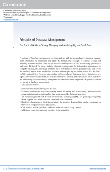
Teorey.book Page 3 Saturday, July 16, 2005 12:57 PM1.2 The Database Life Cycle1.2 The Database Life CycleThe database life cycle incorporates the basic steps involved in designinga global schema of the logical database, allocating data across a computer network, and defining local DBMS-specific schemas. Once thedesign is completed, the life cycle continues with database implementation and maintenance. This chapter contains an overview of the database life cycle, as shown in Figure 1.1. In succeeding chapters, we willfocus on the database design process from the modeling of requirementsthrough logical design (steps I and II below). The result of each step ofthe life cycle is illustrated with a series of diagrams in Figure 1.2. Eachdiagram shows a possible form of the output of each step, so the readercan see the progression of the design process from an idea to actual database implementation. These forms are discussed in much more detail inChapters 2 through 6.I.Requirements analysis. The database requirements are determined by interviewing both the producers and users of data andusing the information to produce a formal requirements specification. That specification includes the data required for processing, the natural data relationships, and the software platform forthe database implementation. As an example, Figure 1.2 (step I)shows the concepts of products, customers, salespersons, andorders being formulated in the mind of the end user during theinterview process.II. Logical design. The global schema, a conceptual data model diagram that shows all the data and their relationships, is developed using techniques such as ER or UML. The data modelconstructs must ultimately be transformed into normalized (global) relations, or tables. The global schema development methodology is the same for either a distributed or centralizeddatabase.a.Conceptual data modeling. The data requirements are analyzedand modeled using an ER or UML diagram that includes, forexample, semantics for optional relationships, ternary relationships, supertypes, and subtypes (categories). Processingrequirements are typically specified using natural language3
Teorey.book Page 4 Saturday, July 16, 2005 12:57 PM4IntroductionCHAPTER 1Information requirementsDetermine requirementsLogical design[multiple views]ModelIntegrate views[single view]Transform to SQL tablesNormalizePhysical designSelect indexes[special ent[else]Monitor and detect changing requirements[defunct]Figure 1.1The database life cycleexpressions or SQL commands, along with the frequency ofoccurrence. Figure 1.2 [step II(a)] shows a possible ER modelrepresentation of the product/customer database in the mindof the end user.
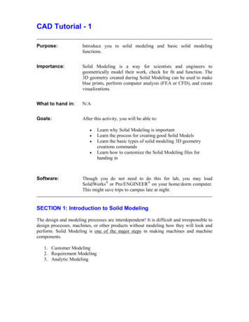
Teorey.book Page 5 Saturday, July 16, 2005 12:57 PM1.2 The Database Life CycleStep I Requirements Analysis (reality)SalespersonsProductsOrdersCustomersStep II Logical designStep II(a) Conceptual data iewNserved-bysold-by1salespersonNStep II(b) View integrationCustomerviewcustomerIntegrationof retailsalesperson’sand customer’sviewsFigure -by1salesperson1fills-outproductLife cycle results, step-by-stepb.View integration. Usually, when the design is large and morethan one person is involved in requirements analysis, multiple views of data and relationships result. To eliminate redundancy and inconsistency from the model, these views musteventually be “rationalized” (resolving inconsistencies due tovariance in taxonomy, context, or perception) and then consolidated into a single global view. View integration requiresthe use of ER semantic tools such as identification of synonyms, aggregation, and generalization. In Figure 1.2 [step5
Teorey.book Page 6 Saturday, July 16, 2005 12:57 PM6CHAPTER 1IntroductionII(b)], two possible views of the product/customer databaseare merged into a single global view based on common datafor customer and order. View integration is also important forapplication integration.c.Transformation of the conceptual data model to SQL tables. Basedon a categorization of data modeling constructs and a set ofmapping rules, each relationship and its associated entitiesare transformed into a set of DBMS-specific candidate relational tables. We will show these transformations in standard SQL in Chapter 5. Redundant tables are eliminated aspart of this process. In our example, the tables in step II(c) ofFigure 1.2 are the result of transformation of the integratedER model in step II(b).d.Normalization of tables. Functional dependencies (FDs) arederived from the conceptual data model diagram and thesemantics of data relationships in the requirements analysis.They represent the dependencies among data elements thatare unique identifiers (keys) of entities. Additional FDs thatrepresent the dependencies among key and nonkey attributeswithin entities can be derived from the requirements specification. Candidate relational tables associated with all derivedFDs are normalized (i.e., modified by decomposing or splitting tables into smaller tables) using standard techniques.Finally, redundancies in the data in normalized candidatetables are analyzed further for possible elimination, with theconstraint that data integrity must be preserved. An exampleof normalization of the Salesperson table into the newSalesperson and SalesVacations tables is shown in Figure1.2 from step II(c) to step II(d).We note here that database tool vendors tend to use theterm logical model to refer to the conceptual data model, andthey use the term physical model to refer to the DBMS-specificimplementation model (e.g., SQL tables). Note also that manyconceptual data models are obtained not from scratch, butfrom the process of reverse engineering from an existing DBMSspecific schema [Silberschatz, Korth, and Sudarshan, 2002].III. Physical design. The physical design step involves the selection of indexes (access methods), partitioning, and clustering ofdata. The logical design methodology in step II simplifies theapproach to designing large relational databases by reducing the
Teorey.book Page 7 Saturday, July 16, 2005 12:57 PM1.2 The Database Life CycleStep II(c) Transformation of the conceptual model to SQL nameqty-in-stockcreate table customer(cust no integer,cust name char(15),cust addr char(30),sales name char(15),prod no integer,primary key (cust no),foreign key (sales name)references salespersonforeign key (prod no)references -noorder-noprod-noStep II(d) Normalization of SQL tablesDecomposition of tables and removal of update eptjob-leveljob-levelvacation-daysStep III Physical designIndexingClusteringPartitioningMaterialized viewsDenormalizationFigure 1.2(continued)number of data dependencies that need to be analyzed. This isaccomplished by inserting conceptual data modeling and integration steps [steps II(a) and II(b) of Figure 1.2] into the tradi-7
Teorey.book Page 8 Saturday, July 16, 2005 12:57 PM8CHAPTER 1Introductiontional relational design approach. The objective of these steps isan accurate representation of reality. Data integrity is preservedthrough normalization of the candidate tables created when theconceptual data model is transformed into a relational model.The purpose of physical design is to optimize performance asclosely as possible.As part of the physical design, the global schema can sometimes be refined in limited ways to reflect processing (query andtransaction) requirements if there are obvious, large gains to bemade in efficiency. This is called denormalization. It consists ofselecting dominant processes on the basis of high frequency,high volume, or explicit priority; defining simple extensions totables that will improve query performance; evaluating total costfor query, update, and storage; and considering the side effects,such as possible loss of integrity. This is particularly importantfor Online Analytical Processing (OLAP) applications.IV. Database implementation, monitoring, and modification. Once the design is completed, the database can be createdthrough implementation of the formal schema using the datadefinition language (DDL) of a DBMS. Then the data manipulation language (DML) can be used to query and update the database, as well as to set up indexes and establish constraints, suchas referential integrity. The language SQL contains both DDLand DML constructs; for example, the create table command represents DDL, and the select command represents DML.As the database begins operation, monitoring indicateswhether performance requirements are being met. If they arenot being satisfied, modifications should be made to improveperformance. Other modifications may be necessary whenrequirements change or when the end users’ expectationsincrease with good performance. Thus, the life cycle continueswith monitoring, redesign, and modifications. In the next twochapters we look first at the basic data modeling concepts andthen—starting in Chapter 4—we apply these concepts to thedatabase design process.1.3 Conceptual Data ModelingConceptual data modeling is the driving component of logical databasedesign. Let us take a look at how this component came about, and why
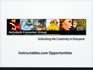
Teorey.book Page 9 Saturday, July 16, 2005 12:57 PM1.3 Conceptual Data Modelingit is important. Schema diagrams were formalized in the 1960s byCharles Bachman. He used rectangles to denote record types anddirected arrows from one record type to another to denote a one-tomany relationship among instances of records of the two types. Theentity-relationship (ER) approach for conceptual data modeling, one ofthe two approaches emphasized in this book and described in detail inChapter 2, was first presented in 1976 by Peter Chen. The Chen form ofthe ER model uses rectangles to specify entities, which are somewhatanalogous to records. It also uses diamond-shaped objects to representthe various types of relationships, which are differentiated by numbersor letters placed on the lines connecting the diamonds to the rectangles.The Unified Modeling Language (UML) was introduced in 1997 byGrady Booch and James Rumbaugh and has become a standard graphical language for specifying and documenting large-scale software systems. The data modeling component of UML (now UML-2) has a greatdeal of similarity with the ER model and will be presented in detail inChapter 3. We will use both the ER model and UML to illustrate the datamodeling and logical database design examples throughout this book.In conceptual data modeling, the overriding emphasis is on simplicity and readability. The goal of conceptual schema design, where the ERand UML approaches are most useful, is to capture real-world datarequirements in a simple and meaningful way that is understandable byboth the database designer and the end user. The end user is the personresponsible for accessing the database and executing queries and updatesthrough the use of DBMS software, and therefore has a vested interest inthe database design process.The ER model has two levels of definition—one that is quite simpleand another that is considerably more complex. The simple level is theone used by most current design tools. It is quite helpful to the databasedesigner who must communicate with end users about their data requirements. At this level you simply describe, in diagram form, the entities,attributes, and relationships that occur in the system to be conceptualized, using semantics that are definable in a data dictionary. Specializedconstructs, such as “weak” entities or mandatory/optional existencenotation, are also usually included in the simple form. But very little elseis included, to avoid cluttering up the ER diagram while the designer’sand end user’s understandings of the model are being reconciled.An example of a simple form of ER model using the Chen notation isshown in Figure 1.3. In this example, we want to keep track of videotapes and customers in a video store. Videos and customers are represented as entities Video and Customer, and the relationship “rents”9
Teorey.book Page 10 Saturday, July 16, 2005 12:57 PM10CHAPTER teVideovideo-idcopy-notitleFigure 1.3A simple form of ER model using the Chen notationshows a many-to-many association between them. Both Video and Customer entities have a few attributes that describe their characteristics,and the relationship “rents” has an attribute due date that representsthe date that a particular video rented by a specific customer must bereturned.From the database practitioner’s standpoint, the simple form of theER model (or UML) is the preferred form for both data modeling and enduser verification. It is easy to learn and applicable to a wide variety ofdesign problems that might be encountered in industry and small businesses. As we will demonstrate, the simple form can be easily translatedinto SQL data definitions, and thus it has an immediate use as an aid fordatabase implementation.The complex level of ER model definition includes concepts that gowell beyond the simple model. It includes concepts from the semanticmodels of artificial intelligence and from competing conceptual datamodels. Data modeling at this level helps the database designer capturemore semantics without having to resort to narrative explanations. It isalso useful to the database application programmer, because certainintegrity constraints defined in the ER model relate directly to code—code that checks range limits on data values and null values, for example. However, such detail in very large data model diagrams actuallydetracts from end user under
Data Structures Hanan Samet Joe Celko’s SQL Programming Style Joe Celko Data Mining, Second Edition: Concepts and Techniques Ian Witten and Eibe Frank Fuzzy Modeling and Genetic Algorithms for Data Mining and Exploration Earl Cox Data Modeling Essentials, Third Edition Gra