Transcription
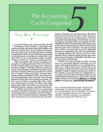
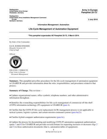
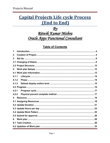
NYS000034Submitted: December 12, 2011EXCERPTEPI2ILife Cycle ManagementPlanning SourcebooksVolume 4: Large Power TransformersTechnical ReportEmergencyDiesel GeneratorStart16%Other9%Scram43%Loss of Off-sitePower8%Down Power12%12%Consequences of Main Transformer EventsOAG 10000438 00000 1
OAG 10000438 000002
Life Cycle ManagementPlanning SourcebooksVolume 4: Large Power Transformers1007422Final Report, March 2003EPRI Project ManagerG. SliterEPRI ·3412 Hillview Avenue, Palo Alto, California 94304· PO Box 10412, Palo Alto, California 94303· USA800.313.3774·650.855.2121 askepri@epri.com www.epri.comOAG 10000438 000003
DISCLAIMER OF WARRANTIES AND LIMITATION OF LIABILITIESTHIS DOCUMENT WAS PREPARED BY THE ORGANIZATION(S) NAMED BELOW AS ANACCOUNT OF WORK SPONSORED OR COSPONSORED BY THE ELECTRIC POWER RESEARCHINSTITUTE, INC. (EPRI). NEITHER EPRI, ANY MEMBER OF EPRI, ANY COSPONSOR, THEORGANIZATION(S) BELOW, NOR ANY PERSON ACTING ON BEHALF OF ANY OF THEM:(A) MAKES ANY WARRANTY OR REPRESENTATION WHATSOEVER, EXPRESS OR IMPLIED, (I)WITH RESPECT TO THE USE OF ANY INFORMATION, APPARATUS, METHOD, PROCESS, ORSIMILAR ITEM DISCLOSED IN THIS DOCUMENT, INCLUDING MERCHANTABILITY AND FITNESSFOR A PARTICULAR PURPOSE, OR (II) THAT SUCH USE DOES NOT INFRINGE ON ORINTERFERE WITH PRIVATELY OWNED RIGHTS, INCLUDING ANY PARTY'S INTELLECTUALPROPERTY, OR (III) THAT THIS DOCUMENT IS SUITABLE TO ANY PARTICULAR USER'SCIRCUMSTANCE; OR(B) ASSUMES RESPONSIBILITY FOR ANY DAMAGES OR OTHER LIABILITY WHATSOEVER(INCLUDING ANY CONSEQUENTIAL DAMAGES, EVEN IF EPRI OR ANY EPRI REPRESENTATIVEHAS BEEN ADVISED OF THE POSSIBILITY OF SUCH DAMAGES) RESULTING FROM YOURSELECTION OR USE OF THIS DOCUMENT OR ANY INFORMATION, APPARATUS, METHOD,PROCESS, OR SIMILAR ITEM DISCLOSED IN THIS DOCUMENT.ORGANIZATION(S) THAT PREPARED THIS DOCUMENTSargent & Lundy, LLCORDERING INFORMATIONRequests for copies of this report should be directed to EPRI Orders and Conferences, 1355 WillowWay, Suite 278, Concord, CA 94520, (800) 313-3774, press 2 or internally x5379, (925) 609-9169,(925) 609-1310 (fax).Electric Power Research Institute and EPRI are registered service marks of the Electric PowerResearch Institute, Inc. EPRI. ELECTRIFY THE WORLD is a service mark of the Electric PowerResearch Institute, Inc.Copyright 2003 Electric Power Research Institute, Inc. All rights reserved.OAG 10000438 000004
CITATIONSThis report was prepared bySargent & Lundy LLC55 East Monroe StreetChicago, IL 60603Principal InvestigatorsB. RaoG. MavropoulosB. GogineniB. LewisThis report describes research sponsored by EPR!.The report is a corporate document that should be cited in the literature in the following manner:Life Cycle Management Sourcebook: Volume 4: Large Power Transformers, EPRI, Palo Alto,CA: 2003. 1007422.IIIOAG 10000438 000005
OAG 10000438 000006
REPORT SUMMARYEPRI is producing a series of "Life Cycle Management Planning Sourcebooks," each containinga compilation of industry experience information and data on aging degradation and historicalperformance for a specific type of system, structure, or component (SSC). This sourcebookprovides information and guidance for implementing cost-effective life cycle management(LCM) planning for large transformers.BackgroundAs explained in the LCM Sourcebook Overview Report (1003058), the industry cost forproducing LCM plans for the many important SSCs in operating plants can be reduced if LCMplanners have an LCM sourcebook of generic industry performance data for each SSC theyaddress. The general objective of EPRI's LCM sourcebook effort is to provide system engineerswith generic information, data, and guidance they can use to generate long-term equipmentreliability plans for plant-specific SSCs (aging and obsolescence management plans optimized interms of plant performance and financial risk). The equipment reliability plan or "LCM plan" fora plant SSC combines industry experience and plant-specific performance data to provide anoptimum maintenance plan, schedule, and cost profile throughout the plant's remainingoperating life.ObjectiveTo provide plant engineers (or their expert consultants) with a compilation of the genericinformation, data, and guidance typically needed to produce a plant-specific LCM plan for largetransformers.ApproachExperts in the maintenance and aging management of large transformer systems followed theLCM process developed in EPRI's LCM Implementation Demonstration Project (1000806). Thescope of the physical system and of component types included in the study was defined.Information and data on historical industry performance of selected types of large transformerswithin this scope were compiled. EPRI LCM utility advisors reviewed the sourcebook prior to itspublication.vOAG 10000438 000007
ResultsThis sourcebook contains information on large transformers such as Generator Step-Up (GSU),Unit Auxiliary Transformer (UAT), and Startup Auxiliary or Reserve Auxiliary Transformers(RATs/SATs). It also contains information on transformer accessories and monitoring devicesfor transformer protection and performance. Information includes performance monitoringissues, component aging mechanisms, aging management maintenance activities, equipmentupgrades, and replacements. Based on this information, alternative LCM plan strategy guidancehas been developed, along with recommendations. The plan strategy guidance providesinformation for implementing cost-effective LCM planning for large transformers. Thesourcebook includes an extensive list of references, many of which are EPRI reports related tothe maintenance and reliability of large power transformers.EPRI PerspectiveUsing this report as a starting point should enable the preparation of plant-specific plans for largetransformers with substantially less effort and cost than if planners had to start from scratch. Thesourcebook captures both industry experience and the expertise of the sourcebook authors. Usingthis sourcebook, plant engineers need only add plant-specific data and information to completean economic evaluation and LCM plan for the plant's large transformers. EPRI plans to sponsoradditional LCM sourcebooks for as many important SSC types as may be useful to operatingplants (perhaps 30 to 40) and as are allowed by industry-wide resources. The process of usingsourcebooks as an aid in preparing LCM plans will improve as the industry gains experience.EPRI welcomes constructive feedback from users and plans to incorporate lessons learned infuture revisions of LCM sourcebooks.KeywordsLife cycle managementNuclear asset managementSystem reliabilityComponent reliabilityLarge transformerViOAG 10000438 000008
CONTENTS1 MANAGEMENT SUMMARY . 1-12 INTRODUCTION .2-12.1 Purpose of LCM Sourcebooks . 2-12.2 Relationship of Sourcebook to LCM Process . 2-12.3 Basis for Selection of the Large Transformers for LCM Sourcebook . 2-13 BASIC INFORMATION ON LARGE TRANSFORMERS . 3-13.1 Safety and Operational Significance . 3-13.2 Large Transformer Functions . 3-23.3 System and Component Boundaries . 3-33.3.1 Transformer Components . 3-33.3.1.1 Tank and Oil Preservation . 3-33.3.1.2 Magnetic Core . 3-53.3.1.3 Windings . 3-53.3.1.4 Insulation System . 3-63.3.1.5 Insulating Liquid . 3-63.3.1.6 Transformer Accessories . 3-63.4 Scope and Equipment Covered by the Sourcebook . 3-94 INDUSTRY OPERATING EXPERIENCE AND PERFORMANCE HISTORY . 4-14.1 Nuclear Industry Experience . .4-14.1.1 Qualitative Data . 4-14.1.2 Quantitative Data . 4-24.1.2.1 Relative Magnitude of Large Transformer Failure Frequency . .4-54.1.3 Maintenance Rule . 4-74.1.4 EPRI PM Basis Templates . .4-84.1.5 Current PM Activities and Candidate PM Tasks . .4-17VllOAG 10000438 000009
4.2 NRC Generic Communications and Other Reports . .4-184.2.1 NRC Communications . 4-184.2.2 Other Nuclear Industry Data . .4-184.3 Experience in Fossil Power Generation and Industrial Facilities . .4-205 GUIDANCE FOR PLANT-SPECIFIC SSC CONDITION AND PERFORMANCEASSESSMENT .5-15.1 Compiling SSC Operating and Performance History . 5-15.1.1 SSC Condition Reviews . 5-25.1.2 Periodic Visual Transformer Inspections . 5-25.1.2.1 Inspection Frequency . 5-35.1.2.2 Typical Inspections . 5-35.1.3 Review of Diagnostic Tests and Monitoring Devices . 5-45.2 Review of Current Maintenance Plans . 5-75.2.1 Compiling Maintenance History . 5-75.2.2 Inventory of Current Maintenance Activities . 5-75.2.2.1 Pumps . 5-85.2.2.2 Bushings . 5-95.2.2.3 Control and Protective Devices . 5-95.2.2.4 Gas Cushion Oil Preservation . 5-105.3 Conducting the Condition and Performance Assessment. . 5-105.4 Condition Monitoring Technologies . 5-125.4.1 Recommended Test Sequences . 5-125.4.2 Gas-In-Oil Analysis . 5-135.4.3 Dielectric Strength Guidelines . 5-145.4.4 Dielectric Tests . 5-145.4.5 Water In Oil Tests . 5-155.4.6 Water Content of Paper Insulation . 5-155.4.7 Oil Power Factor . 5-165.4.8 Oil Interfacial Tension . 5-175.4.9 Condition Monitoring Systems . 5-185.4.9.1 Gas-In-Oil Sensors . 5-185.4.9.2 Temperature Sensors . 5-185.4.9.3 Oil Level Gauges . 5-195.4.9.4 Rate-of-Rise Relays . 5-19V111OAG10000438 000010
5.4.9.5 Gas Collector Relay . 5-195.4.9.6 Oil Pump Performance Sensors . 5-205.4.9.7 Load Tap Changer (LTC) Monitors . 5-205.4.9.8 Infrared Thermography . 5-215.4.9.9 Water-In-Oil Sensors . 5-215.4.9.10 Partial Discharge Detection . 5-215.4.9.11 Acoustic Emission Devices . 5-215.4.9.12 Acoustic Sensors . 5-225.4.9.13 Internal Sensors . 5-226 GENERIC AGING AND OBSOLESCENCE ASSESSMENT . 6-16.1 Aging Mechanism Review . 6-16.1.1 Other Sources of Generic Failure Data . 6-46.2 Expected Lifetimes of Major Components . 6-146.3 Technical Obsolescence . 6-147 GENERIC ALTERNATIVE LCM PLANS . 7-17.1 Plant Operating Strategies and Types of LCM Planning Alternatives . 7-17.1.1 Plant Strategy 1: Operate the plant for the currently licensed period of 40years . 7-17.1.2 Plant Strategy 2: Operate the plant for 60 years under a License RenewalProgram . 7-27.2 Development of Detailed Alternative LCM Plans . 7-27.3 Hypothetical Illustration of Assembling LCM Planning Alternatives . 7-38 GUIDANCE FOR ESTIMATING FUTURE FAILURE RATES . 8-19 PLANT-SPECIFIC GUIDANCE FOR ECONOMIC MODELING . 9-110 INFORMATION SOURCES AND REFERENCES . 10-1IXOAG10000438 000011
OAG 10000438 0000 12
LIST OF FIGURESFigure 2-1 a LCM Planning Flowchart - SSC Categorization and Selection . 2-2Figure 2-1 b LCM Planning Flowchart - Technical and Economic Evaluation . 2-3Figure 2-1 c LCM Planning Flowchart - Implementation . 2-4Figure 3-1 Typical Generating Station One-Line Diagram . 3-4Figure 4-1 Number of Transformer Events Per Year . .4-2Figure 4-2 Transformer Events . 4-4Figure 4-3 Causes of Transformer Events . 4-4Figure 4-4 Results of Transformer Events . 4-6Figure 4-5 Transformer Failure Rate Per Plant and Per year . .4-7Figure 4-6 Number of Transformer Failures by Year . .4-22XlOAGI0000438 000013
OAG 10000438 0000 14
LIST OF TABLESTable 4-1 Transformer Events 1991 - 2001 . .4-3Table 4-2 Failure Rates Calculated from EPIX (SOER 02-3) Data . .4-5Table 4-3 Transformers (Station-Type, Oil-Immersed) . 4-9Table 4-4 PM Tasks and Degradation Mechanisms (from EPRI TR-106857, V. 38) . .4-11Table 4-5 Maintenance Tests, Routine Maintenance, Inspections and Frequency . .4-17Table 4-6 European Nuclear Power Plant Failure Data . .4-21Table 4-7 Analysis of Power Transformer Failures for 1975, 1988, and 1998 . .4-21Table 4-8 Transformer Component Failures . 4-23Table 5-1 Dissolved Gas Concentration . 5-6Table 5-2 Recommended Test Sequences . 5-12Table 5-3 Typical Maintenance Oil Test Frequency . 5-13Table 5-4 Dielectric Strength Guidelines . 5-14Table 5-5 Maximum Water-in-Oil Test . 5-15Table 5-6 Maximum Water Content . 5-16Table 5-7 Maximum Acceptable Percent Power Factors of Oil . 5-16Table 5-8 Oil Interfacial Test . 5-17Table 6-1 Common Maintenance Issues and Surveillance Techniques . 6-2Table 6-2 Degradation Mechanisms . 6-5Table 6-3 Application of Obsolescence Evaluation Criteria for a Cooling Fan . 6-15Table 7-1 Guide for Staging of Pumps on Forced-Oil-Air (FOA) Transformers . 7-3Table 7-2 Hypothetical Example for Single Tank, Single Unit, 3-Phase Transformer . 7-5X111OAG10000438 000015
OAG 10000438 0000 16
1MANAGEMENT SUMMARYThis Life Cycle Management (LCM) Planning Sourcebook for large transformers will help guideplant engineers or expert consultants in preparing a life cycle management plan (long-termreliability plan) for large transformers at their plants. The generic information and guidancepresented in this sourcebook is expected to help plant engineers focus on areas where there maybe significant opportunities for cost-effective improvements. Use of the sourcebook will reducethe cost of preparing a plant-specific LCM plan by approximately a third compared to startingfrom scratch.The sourcebook identifies component aging mechanisms together with the maintenance activitiesto manage them, as well as obsolescence issues and available management options. It provideshypothetical LCM plan alternatives to serve as starting points for plant-specific applications.Guidance consists mainly of generic industry-wide information and references on largetransformers and their components. Guidance is provided on how to build alternative LCMplans that can be considered during long-term planning for the critical components. Dependingon the level of detail desired for the plant-specific LCM plan, the generic data in this sourcebookmay allow engineers to identifY areas where significant cost-effective improvements or reductionin maintenance activity can be realized and where long term planning for emerging obsolescenceissues can be developed.Important reasons for covering large power transformers in a sourcebook are: High reliability of large transformers is important to economic plant operation. At some plants, inspection and maintenance of large power transformers is not given a highpriority. Some of the large power transformers and their components may become obsolete in the nearfuture, requiring replacement, substitution, or upgrades, particularly for plants contemplatinglicense renewal or power uprate. Increased load on the main transformer due to power uprate and increased electrical loads onthe auxiliary transformers have reduced transformer life.Large transformer industry reliability issues addressed by this study are: Monitoring of the oil and insulation quality is paramount to preserving the life of atransformer. Although transformers are designed and built for 30 to 40 year service life, operating andmaintenance practices can affect their service life span.1-1OAGI0000438 000017
Management SummaryThe potential alternative LCM plans considered include: Implementing diagnostic maintenance, which includes programs such as thermography, oilanalysis, etc. Establishing/revising Preventive Maintenance (PM)/Predictive Maintenance (PdM) tasks andschedules. Establishing refurbishment program. Maintaining a spare in the same fashion as the operating transformers. Establishing other options for spare transformers on a pre-negotiated basis with vendors orother plants.1-2OAGI0000438 000018
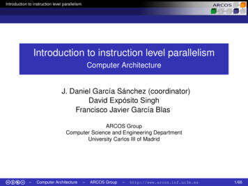
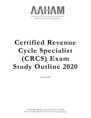
2INTRODUCTION2.1 Purpose of LCM SourcebooksAs indicated in the Life Cycle Management (LCM) Sourcebook Overview Report [1], an LCMsourcebook is a compilation of generic information, data, and guidance an engineer typicallyneeds to produce a plant-specific LCM plan for a System, Structure or Component (SSC). Thissourcebook will enable plant engineers or outside experts to develop a plant-specific LCM planfor large transformers with substantially less effort than if they had to start from scratch. Theengineer need only add plant-specific data and information to complete an economic evaluationand LCM plan for large transformers.It must be recognized that not all generic information in a sourcebook applies to every plant.Some of the data can serve for comparison or benchmarking when preparing plant-specific LCMplans. Other data may show indicators or precursors to problems not yet experienced at a givenplant. Therefore, caution and guidance is provided in the plant-specific guidance sections(Sections 5,8, and 9 of the sourcebook) for the use and application of the generic information.These sections also contain useful tips and lessons-learned from the EPRI LCM PlantImplementation Demonstration Program [2].2.2 Relationship of Sourcebook to LCM ProcessThe process steps for LCM planning are described in detail in the EPRI LCM Report [2]. TheLCM planning flowchart (Figures 2-1a, b, c of this large transformer sourcebook) is essentiallythe same as Figure 1-1 of the LCM Sourcebook Overview Report [1]. The chart is segmentedinto the four elements of the LCM planning process: SSC categorization/selection, technicalevaluation, economic evaluation, and implementation. Process step numbering has beenmaintained consistent with the LCM report.2.3 Basis for Selection of the Large Transformers for LCM SourcebookAn LCM Sourcebook for large transformers has been prepared because the component met thefollowing important objectives of the SSC selection process: Applicability to both BWRs and PWRs Importance to safety risk and regulatory concern Importance to power production Subjected to significant degradation and obsolescence Have a history of chronic maintenance problems2-1OAGI0000438 000019
IntroductionFigure 2-1aLCM Planning Flowchart - SSC Categorization and SelectionLevel A: Critical SSCs warrantingin-depth LCM PlanningLevelAsses. 1 - - - - - - - - - - - - - - 4 - . - . 1 already covered byin depth strategicSteam generators, fuel, reactorplanning modelsinternals, elc.Identify SSCsimportant 10safely, aV lilabili!yand costDetermineappropriate LCMevaluation levelLevel B: Important SSCs wam!lltinglCM PlllnningSpeciji, SSCs: turbine gellerator, buriedcables, buried piping, RPV headnozzles, etc,Signi1icant Commodilies: major pumps,compressors. valves, heal exchangers,illSlrumentation, etc.ToFigure 2-1blevel C' SSCs for which existingmaintenance plans are adequate andformal LCM plans are not warrantedLevel C and 0SSCs informalperformance andcost reviewslevel D: SSGs for which !1() formalmaintenance plan is, necessaryG,li(!.,J!1(:{) provld (l inTOpic& iiiit aiidi s iii iiiSOlJrceoookSOl.lr eb()ol\Figure 2-1aLCM Planning Flowchart - SSC Categorization and Selection2-2OAG 10000438 000020
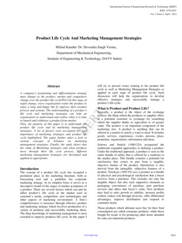
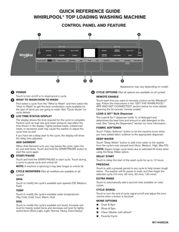
IntroductionFigure 2-1blCM Planning Flowchart - Technical and Economic Evaluationr - - - - - - - - -IINo changes to1IIIcllt{efltIIImaintenance planOptimize currentmaintenanceprogramIIdentifyalternative LCMplans compatiblewith plan!operating lifestrategyFromFigure 2-13II1IIMalle designchanges ormodifit:allonsReplace parts#13-17f----,LCM approachesLCompile failute rateand cost data foraltemative LCMplansSelect optimumSSC level LCMplan. ·( Ukjari( pr&yiii6 l iii··SouIWbool'SeeFigure 2 1c. Tw!i:s not aciiii sii6(j iii··Souro"b()QkFigure 2-1bLCM Planning Flowchart - Technical and Economic Evaluation2-3OAG 10000438 000021
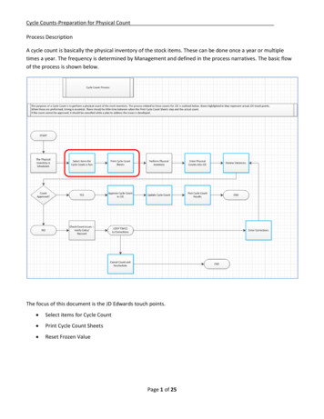
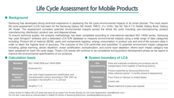
IntroductionFigure 2-1cLCM Planning Flowchart - Implementation,------------1IIIRoll-up plantbudgetI .IIILevel A sses specificallyIIlisted: Steam generators,fuel, decommissioninQ,Ireact{)f internals, etc.!!!IIIISpecilic SSCs:Turbine generator, bufie lcables. burled piping, RPVhead nozzles, ele.IFromFigure 2-1 bI. IIIIIIIIIIIIIIL -Review antiapprove sse levellCM plansImplemen! planand track:performanceIterate to Step #18to IncorporateperformancefeedbackSignificant commodities:Pump1;. cOmf)feSSofS, vqlve: ,.heat exchangers, etc.ssesLevel C and Dcovered by generalma intenanc.e budgetIIII!Olhef C{lsts ienSllre thatcosts are n{lt duplicatedoverall budget amiinputs); staff, materials,regulatory compliance. taxes,etc.sse----1#21 1-ii GUI'fjance prOVided H"1Soufc"pookTopics flet ad·dr".s d inSOlJfc"bookFigure 2-1cLCM Planning Flowchart - Implementation2-4OAG 10000438 000022
3BASIC INFORMATION ON LARGE TRANSFORMERSThis section addresses step number 7 in Figure 2-la. Large transformers are used in power plantsto connect the main generator to the high-voltage (RV) transmission system. Large transformersare also used to connect the plant and off-site sources to the plant's distribution system foroperation of auxiliary equipment at medium and low voltages. The large transformers ofparticular interest to the power plants range in size from 2.5 MVA to 1500 MVA with a voltagerange of 4.16 kV to 765 kV and are typically installed outdoors. The characteristics of largetransformers do not depend on whether the plant is a PWR or a BWR, but on the size of thetransformer (i.e., MVA rating). Larger MVA range transformers are custom designed to meetthe parameters such as voltages, short circuit currents, etc., specified by the plant requirements.This sourcebook will focus on Generator Step-Up (GSU) or Unit Transformers (UT), UnitAuxiliary Transformers (UAT), Startup Auxiliary Transformers (SAT), also called ReserveAuxiliary Transformers (RAT). EPRI's "Power Transformer Application and MaintenanceGuide" [5], provides a list of the subject transformers in nuclear plants located in the US andCanada. The list indicates the manufacturers, ratings, and types.3.1 Safety and Operational SignificanceThe GSU transformer is used to step-up plant generated voltage (18 to 26 kV) to the requiredgrid voltage (115 to 765 kV). In contrast, the reserve and auxiliary transformers step-down thevoltage to the desired plant system voltages (4.16 to 13 kV). The GSU transformers are nonsafety-related but the loss of a main transformer could cause scrams, and/or transients, with theresulting loss of power production. The auxiliary transformers are typically non-safety-related,but they are "important to safety" as they supply power to the safety-related buses and also serveas an off-site power source for plant operation and shutdown. These transformers, along withthe offsite power system, are designed to meet the nuclear plant general design criteria as statedin the FSAR and Te
Experts in the maintenance and aging management of large transformer systems followed the LCM process developed in EPRI's LCM Implementation Demonstration Project (1000806). The scope of the physical system