Transcription
CaleffiNorthAmerica,America,Inc.Caleffi NorthInc.th3883W. Milwaukee9850 South54 StreetRdMilwaukee,Wisconsin 53208Franklin, WI 53132T: 414.238.2360414.421.1000 F:T:F:414.421.2878414.238.2366Dear Hydronic and Plumbing Professional,Dear Hydronic Professional,Students returning toschool after summer break can attest that it’s good for theWelcome to the 2nd edition of idronics – Caleffi’s semi-annual design journal forprofessorto start with a review of the basics. Jumping into Thermodynamicshydronic professionals.401 without a refresher can make grasping more advanced topics difficult.It’sThein thisspirit thatwe created12th ineditionof idronicsHydronicof idronicswas thisreleasedJanuary2007 andentitleddistributedto over1st editionFundamentals.80,000 people in North America. It focused on the topic hydraulic separation. Fromthe feedback received, it’s evident we attained our goal of explaining the benefitsA Technical JournalfromCaleffi Hydronic SolutionsCALEFFI NORTH AMERICA, INC3883 W. Milwaukee RdMilwaukee, Wisconsin 53208 USATel: 414-238-2360FAX: 414-238-2366E-mail: idronics@caleffi.comWebsite: www.caleffi.usTo receive future idronics issuesFREE, register online www.caleffi.us Copyright 2011Caleffi North America, Inc.Printed: Milwaukee, Wisconsin USAand properapplicationof facethis moderntechniquesystems.Feedbackfromour face totraining designprograms,as wellforashydronicthose offeredonline, frequently asks for explanation of basic design principles, or why certainIf you haven’t yet received a copy of idronics #1, you can do so by sending in theinstallationpractices are followed. So, like a professor giving a review at theattached reader response card, or by registering online at www.caleffi.us. Thestartofasemester,issueidronicscreatedto review,refresh, andpublication will bethismailedto ofyoufree of wascharge.You canalso downloadthereinvigorateyour understandingof theourfundamentalscomplete journalas a PDF file fromWeb site. that every hydronic systemrelies on. With a solid grasp of these fundamentals you’ll be able to designThis secondeditionaddressesand dirtin hydroniccomfort.systems. You’llThoughnotbea newefficientand o our industry,the useof reparedfor the morespecializedthat will becoming infuture athoroughunderstanding of the harmful effects of air and dirt, as well as knowledgeissuesof idronicson how to eliminate them. Doing so helps ensure the systems you design willoperate at peak efficiency and provide long trouble-free service.This issue also makes frequent reference to past issues that have dealt withspecifictopicsmoreWeofencourageto getthese previousWe trustyou inwillfind detail.this issueidronics ayouusefuleducationaltool andissuesa handyby referencegoing to theidronicslinkhydronicat www.caleffi.us,and downloadingthe PDFfiles.for yourfuturesystem designs.We also encourageyouto sendus feedbackthisalsoissueof idronicsusinghardthe attachedreaderWhilethere, youoncanregisterto receivecopies offutureresponseissues. card or bye-mailing us at idronics@caleffi.com.We hope you enjoy this issue and encourage you to send us any feedback aboutidronics by e-mailing us at idronics@caleffi.com.Sincerely,Mark OlsonMark OlsonGeneral Manager,Caleffi North America, Inc.General Manager & CEOINDEX1. Introduction7: Essential hydronics hardware2. Benefits of hydronic systems8: Heat emitter options3: A brief history of hydronics9. Hydronic distribution systems4: The basic hydronic circuit10: Control concepts and hardware5: Physical operating conditions11: Examples of modern hydronic systemsin hydronic systemsAPPENDIX A: Schematic symbols6: Hydronic heat sourcesAPPENDIX B: Buffer tank sizingDisclaimer: Caleffi makes no warranty that the information presented in idronics meets the mechanical, electrical or other code requirements applicable within agiven jurisdiction. The diagrams presented in idronics are conceptual, and do not represent complete schematics for any specific installation. Local codes mayrequire differences in design, or safety devices relative to those shown in idronics. It is the responsibility of those adapting any information presented in idronics toverify that such adaptations meet or exceed local code requirements.10%Cert no. XXX-XXX-XXXX
Hydronic Fundamentals1. INTRODUCTION2. BENEFITS OF HYDRONIC SYSTEMSThis is a special issue of idronics. Unlike past issues,which have focused largely on one topic, this issuebroadly describes the fundamentals of hydronic systems.These fundamentals are the foundation of good systemdesign and proper installation. When clearly understoodand applied, they allow designers to create systemsthat deliver superior comfort, energy efficiency andlong-term reliability. When ignored, the results are likelyto be inefficient operation, wasted materials, excessivecallbacks and unhappy customers.Modern hydronics technology is a “media” that skilleddesigners can use to create an appropriate heating orcooling solution for almost any building. The versatility ofmodern hydronics technology is unmatched by any othermeans of heating or cooling buildings.This issue was outlined based on suggestions from manyhydronic heating professionals. They indicated the needfor an issue directed at those new to hydronics, as wellas one that could refresh and clarify basic concepts tothose already working with hydronic systems. This issuefills that need.Starting from scratch, a thorough discussion of hydronicstechnology would require hundreds of pages. Fortunately,previous issues of idronics have already discussed manyspecific topics related to hydronic system design inconsiderable detail. This issue will leverage that information.This section highlights the benefits of modern hydronicsystems, both to those designing and installing systems,and to the occupants of buildings that are heated orcooled using hydronics technology. It is essential thatheating and cooling professionals understand the basisfor these benefits and effectively communicate themto those who are trying to select a means of heating orcooling for their building.COMFORT:Every heating system affects the health, productivity andgeneral well-being of numerous people over many years.The ability of that system to provide thermal comfortis of paramount importance and should be the primaryobjective of any heating system designer or installer.Figure 2-1While reading through this issue, you will find frequentreferences to previous issues. Watch for the idronicsicon shown below, followed by reference to one or moreprevious issues.References to issues of idronicsAll of these other issues are freely available asdownloadable PDF files under the idronics archive link atwww.caleffi.us.com. You are encouraged to download allof them, and keep them available for reference.3
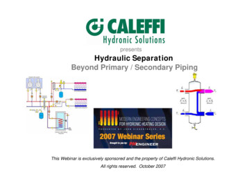
Few people don’t appreciate a warm comfortable houseon a cold winter day. A place that helps them forget aboutsnow, ice and wind as they walk in the door. A place thatencourages a sense of well-being and relaxation.heat to leave a person’s body at the same rate as itis generated, that person feels comfortable. If heat isreleased faster or slower than the rate it is produced,some degree of discomfort is experienced.Still, the average North American homeowner spendslittle time thinking about his or her heating system. Manyview such systems as necessary but uninteresting. Whenconstruction budgets are strained, it is often the heatingsystem that gets compromised to save money for other,seemingly more important amenities. In many cases, it isthe homebuilder rather than the homeowner who selectsthe heating system. Builders often have different prioritiesfrom those who will live with, maintain and pay for theoperation of that system.A normal adult engaged in light activity generates heatthrough metabolism at a rate of about 400 Btu/hr. The bodyreleases this heat through several processes, includingconvection, radiation, evaporation and conduction.In many cases, people who have lived with uncomfortableheating systems don’t realize what they have beenmissing. Many would welcome the opportunity to live orwork in truly comfortable buildings and would willinglyspend more money, if necessary, to do so. Successfulheating professionals take the time to discuss withpotential clients the full range of benefits of hydronicsystems as well as the price.Contrary to common belief, comfort during the heatingseason is not solely determined by indoor air temperature.Comfort is achieved and maintained by controlling howthe body loses heat. When interior conditions allowFigure 2-2For indoor environments in colder weather, thermalradiation and convection typically account for almost75% of the total heat output from the body. Heat loss bythermal radiation alone can be 50% to 60% of the totalheat loss, especially within buildings that have cold wall,floor or ceiling surfaces.Properly designed hydronic systems control the airtemperature as well as the surface temperature of roomsto maintain optimal comfort. A hydronically heated flooror ceiling can raise the average surface temperature ofrooms. Since the human body is especially responsiveto radiant heat loss, these warm surfaces significantlyenhance comfort. Proper indoor humidity is also easierto maintain in buildings using hydronic heating due toreduced air leakage.Factors such as activity level, age and general healthdetermine what a comfortable environment is for a givenindividual. When several people are living or working ina common environment, any one of them might feel toohot, too cold or just right. Heating systems that allowdifferent zones of a building to be maintained at differenttemperatures can adapt to the comfort needs of severalindividuals. Hydronic heating systems are easy to zoneusing several different approaches.See idronics #5 for a complete discussion onhow to zone hydronic heating systems.ENERGY SAVINGS:Ideally, a building’s rate of heat loss would not beinfluenced by how that heat is replaced. However,evidence has shown that otherwise identical buildingscan have significantly different rates of heat loss basedon the types of heating systems installed. Buildings withhydronic heating systems have demonstrated a tendencyfor lower heat loss compared to equivalent structureswith forced-air heating systems.There are several reasons for this reduced heat loss.One is that hydronic systems, unlike forced-air systems,4
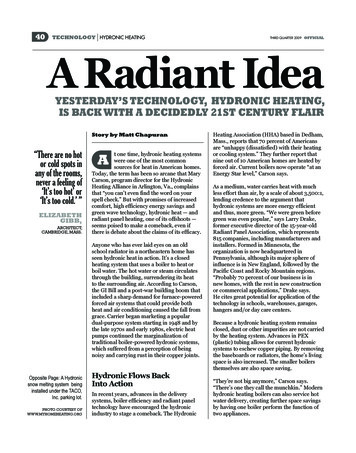
have very little effect on room air pressure while operating. Themore significant changes in room air pressure created by forced-airsystems can increase the rate of outside air infiltration or inside airexfiltration through the exterior surfaces. The greater the rate of airleakage, the greater the rate of heat loss.Figure 2-357 ºF94 ºFtemperaturevariation with!forced-air!heatingAnother factor affecting building energy use is air temperaturestratification (e.g., the tendency of warm air to rise toward the ceilingwhile cool air settles to the floor). Stratification tends to be worsened byhigh ceilings, poor air circulation and heating systems that supply air intorooms at high temperatures. Maintaining comfortable temperatures inthe occupied areas of rooms plagued with a high degree of temperaturestratification leads to significantly higher air temperatures near theceiling. This increases heat loss through the ceiling.Hydronic heat emitters that transfer the majority of their heat outputby thermal radiation reduce, and in some cases eliminate, undesirableair temperature stratification. This reduces heat loss through ceilingsand allows comfort to be maintained at lower air temperatures.idealtemperature!variation65 ºF82 ºFForced-air heating58 ºFtemperaturevariation with!radiant floor!heatingFigure 2-3 shows a comparison between the undesirable airtemperature stratification created by forced-air systems operating withpoorly placed registers versus the desirable “reverse” stratificationcreated by hydronic radiant floor heating.LOW DISTRIBUTION ENERGY:Properly designed hydronic systems use significantly less energy tomove heat from where it is produced to where it is needed. A welldesigned hydronic system, using a modern high-efficiency circulator,can deliver a given rate of heat transport using less than 10% ofthe electrical energy required by the blower of a forced-air heatingsystem transporting heat at the same rate. This is a very importantadvantage of hydronic systems—one that can save thousands ofdollars in operating cost over the design life of a typical residentialheating system. This savings is often overlooked or not presentedwith sufficient emphasis by those who only consider the energy useassociated with producing heat.Figure 2-4idealtemperature!variation79 ºF82 ºFHydronic floor heating5
VERSATILITY:Modern hydronics technology offers virtually unlimitedpotential to accommodate the comfort needs, usage,aesthetic tastes and budget constraints of almost anybuilding. A single system can be designed to supply spaceheating, domestic hot water and specialty loads such assnowmelting or pool heating. These “multi-load” systemsreduce installation costs because redundant componentsFigure 2-5are eliminated. They also improve the efficiency of boilersand reduce fuel usage relative to systems where each loadis served by its own heat source.Hydronic systems can combine a variety of heat emitters forspace heating. For example, hydronic radiant floor heatingmay be used to maintain comfort in a basement, while thefirst and second floors are heated by panel radiators.A wide variety of hydronic heat sources are available.They include boilers fired by gas, oil, electricity, firewoodand pellets; geothermal and air-source heat pumps;solar collectors and devices that adapt to specialcircumstances or opportunities, such as “time-of-use”electrical rates or waste heat recovery.CLEAN OPERATION:A common complaint about forced-air heating is itspropensity to move dust and other airborne particles suchas pollen and smoke throughout a building. In buildingswhere air-filtering equipment is either of poor quality orimproperly maintained, dust streaks around ceiling andwall diffusers are often evident, as seen in Figure 2-8.Figure 2-6Figure 2-8Figure 2-9Figure 2-7Courtesy of Gary Todd6
Eventually duct systems and other air-handling equipmentrequire internal cleaning to remove dust and dirt that hasaccumulated over several years of operation, as seen inFigure 2-9.Figure 2-11In contrast, few hydronic systems involve forced-aircirculation. Those that do create room air circulationrather than building air circulation. This reduces thedispersal of airborne particles and microorganisms. Thisis a major benefit in situations where air cleanliness isimperative, such as for people with allergies, health carefacilities or laboratories.QUIET OPERATION:Many people view their home as an escape from thenoise and stress associated with modern life. As such,the home should provide “acoustical comfort” as well asthermal comfort. When it’s time to relax, noise from anyheating or cooling system is certainly unwelcome.Figure 2-10Source: Earth Advantage InstituteThis situation leads to ducts being installed in unconditionedattics or “hidden” behind interior soffits, as seen in Figure2-12. Such situations can also result in undersized ductsor inadequate placement of ducts. Occupants eventuallypay the price in terms of reduced comfort, noise, increasedheat loss or compromised aesthetics.Figure 2-12A properly designed and installed hydronic system canoperate with virtually no detectable noise in the occupiedareas of a home. These characteristics make hydronicheating ideal in sound-sensitive areas such as hometheaters, reading rooms or sleeping areas.Source: http://angthebuilder.blogspot.comNONINVASIVE INSTALLATION:Consider the difficulty encountered when installingadequate and properly sized ducting within a typicalwood-framed house. If the house happens to useopen web floor trusses rather than traditional floorjoists, the ducting may be able to be installed asshown in Figure 2-11.However, most homes are not framed in this manner.Instead, they have solid floor joists. Making the cutsnecessary to accommodate properly sized ducting in thistype of framing would destroy its structural integrity.Source: U.S. Department of Energy7
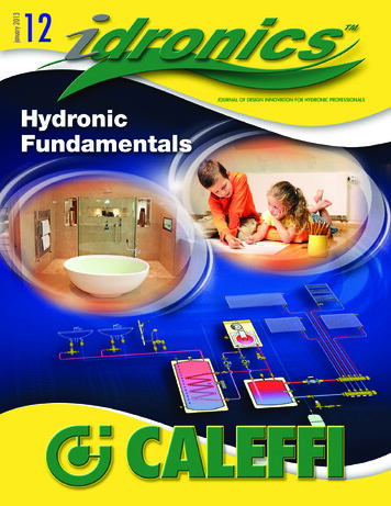
By comparison, modern hydronic systems are easyto integrate into buildings without compromising theirstructure or the aesthetic character of the space. Thereason for this is the high heat capacity of water. A givenvolume of water can absorb almost 3,500 times moreheat as the same volume of air for the same temperaturechange. This means that the volume of water that mustbe moved through a building to deliver a given amount ofheat is only about 0.03% that of air! This greatly reducesthe size of the distribution “conduit.”For example, a 3/4-inch diameter tube carrying water at6 gallons per minute around a hydronic system operatingwith a 20ºF temperature drop transports as much heatas a 14” by 8” duct carrying 130ºF air at 1,000 feet perminute. Figure 2-13 depicts these two options, side byside, in true proportion.Hydronic systems using small diameter flexible tubingare also much easier than ducting to retrofit into existingbuildings. The tubing can be routed through closed framingspaces much like electrical cable, as shown in Figure 2-14.For buildings where utility space is minimal, small wallhung boilers can often be mounted in a closet or smallalcove, as seen in Figure 2-15. In many cases, thesecompact boilers can supply the building’s domestic hotwater as well as its heat. The entire “mechanical room”may have a footprint of less than 10 square feet.Figure 2-15Figure 2-13this cut would destroy the load-carryingability of the floor joists2 x 12 joist14" x 8" duct3/4" tubeNotching into 2 x 12 floor joists to accommodate the14” by 8” duct would destroy their structural integrity.However, small-diameter flexible tubing is easily routedthrough the center of the same framing with negligibleeffect on structure.Figure 2-14ABILITY TO ZONE:The purpose of any heating system is to provide comfortin all areas of a building throughout the heating season.Doing so requires systems that can adapt to the lifestyle ofthe building occupants, as well as the constantly changingthermal conditions inside and outside of a building.Imagine a building in which all rooms have the same floorarea. Someone not familiar with heating system designmight assume that each room, because they are all thesame size, requires the same rate of heat input. Althoughsuch an assumption might be intuitive and simplistic, itfails to recognize differences in the thermal characteristicsof the rooms. Some rooms might have only one exposed8
Figure 2-16M. BATHROOMMASTER BEDROOMZONE 2DLAUNDRYboilerKITCHENThe combination of room thermalcharacteristics, outdoor conditionsand occupant expectations presentsa complex and dynamic challengefor the building’s heating system asit attempts to maintain comfort.GARAGEZONE 3MECHANICALWDHWWALK-INCLOSETBeyond these differences areconditionsimposedbytheoccupants. One person might prefersleeping in a room maintained at63ºF, while another feels chilled iftheir bedroom is anything less than72ºF. One occupant might prefera living room maintained at 70ºFwhile relaxed and reading, whileanother wants the temperature inthe exercise room at 65ºF during aworkout.ZONE 1One method that has long been usedto help meet this challenge is dividingthe building’s heating system intozones. A zone is any area of a buildingfor which indoor air temperature iscontrolled by a single thermostat (orother temperature-sensing device).A zone can be as small as a single room, or it may be aslarge as an entire building.LIVING & DININGFigure 2-17heatemitterszonevalvesFigure 2-16 shows a zoning plan for the first floor of ahouse. The living room, kitchen, half-bath and laundryare combined into a single zone. The master bedroom,master bathroom and closet form another zone. Thegarage is also treated as a separate zone.There are several ways to create zoned hydronic heatingand cooling systems. All of these approaches are simplerand less expensive than equivalent zoning of a forcedair system. Figure 2-17 shows part of a hydronic pipingschematic in which zone valves are used to control theflow of heated water to each heat emitter.Proper zoning accounts for differences in the activitiesthat occur in different areas of a building, as well asdifferences in preferred comfort levels, interior heat gainand the desire to reduce energy use through reducedtemperature settings (e.g., “setback”).wall, while other rooms might have two or three exposedwalls. Some rooms might have a generous window area,while other rooms have no windows. The air leakage andpotential for sunlight to enter through windows may alsovary from one room to another.idronics #5 provides a more in-depth discussion ofmodern zoning methods for hydronic systems.9
3: A BRIEF HISTORY OF HYDRONICSFigure 3-1Water-based hydronic heating systems in North Americadate back over a century. Most accounts point to waterbased systems evolving from steam-based systems. Thelatter were the first means of equipping buildings with“central” heating. Before that, heating was done withfireplaces and wood-fired or coal-fired stoves locatedthroughout the building.Although steam systems were effective, and some arestill in use today, they impose several fundamentallimitations on how the system must be designed andinstalled.First, in a low-pressure steam heating system, the boilerneeds to be located at the bottom of the distributionsystem. This is necessary to allow the condensate (steamthat has cooled and changed back to liquid water) to flowback to the boiler.Second, steam boilers generally need to operate atrelatively high temperatures. There are exceptions tothis (e.g., vacuum-based steam systems), but they arenot common. The high temperatures needed to producesteam essentially eliminate contemporary heat sourceoptions such as solar thermal collectors or heat pumps.Third, steam systems require carefully planned metalpiping systems. The piping must be pitched forcondensate return to the boiler. Fittings on steam mainsmust be properly oriented. The temperatures at whichmost steam heating systems operate preclude the useof polymer piping such as PEX or polypropylene. Pipesizes also tend to be larger than those required forwater-based distribution systems. The installation costof the iron or steel piping required in steam systems hassignificantly increased over the last decade.Most steam heating systems use cast iron radiatorsas their heat emitters. An example of such a radiatoris shown in Figure 3-1. While such radiators can bevery effective, and are often elegant in detail, theyare very heavy. This significantly increases the costof transportation and installation. The manufacturingprocedures used for cast iron have also become moredifficult to sustain, especially in North America, due toincreasing energy cost and environmental regulations.Finally, the iron and steel piping used in steam heatingsystems at various times contains steam, liquid waterand air. The combination of water, oxygen from air andiron creates iron oxides within the piping and radiators.These oxides eventually form a sludge that reduces10heat transfer in the radiators and must be periodically“blown down” from steam producing boilers.Steam heating deserves distinct recognition withinthe evolution of North American heating systems.Thousands of innovative products have been producedto improve the performance of steam heating systemsover several decades. Still, given the resources andinstallation details they require, the current worldwidecosts of energy and the availability of many competingmethods of heat generation and delivery, very few newsteam heating systems are being installed. The presentmarket for steam heating is almost entirely basedon replacement of older steam boilers, radiators andrelated hardware. Water, in liquid form, is the future ofhydronic heating.EARLY WATER-BASED SYSTEMS:Water-based central heating systems were originallydeveloped in the late 1800s. During that time, and forseveral decades to follow, there were no electricallypowered circulators available. The only “propulsioneffect” available to move water through systems wasthe differential pressure created by the simultaneouspresence of hot and cool water. Hot water in the boiler isslightly lighter than cooler water in the return side piping.This creates a slight weight imbalance that causeshot water to rise while cool water descends, and thus
circulation occurs within the system. Early designersquantified this effect, as shown in Figure 3-2, which datesfrom an 1896 heating manual.Figure 3-2Notice that the piping is either vertical or slightly sloped.This slope encourages buoyancy driven flow and helpsprevent air pockets from forming within the piping. Suchpockets could block flow.Many of these early systems contained an expansiontank at the high point in the system, often in the atticof a house. This tank was usually sized to 1/36th of thetotal system volume, and equipped with an overflowpipe leading to a drain or outside the building.When heated, the water in the system expanded,possibly to the point where some would spill out of theoverflow pipe from the expansion tank. As the systemcooled, the water would decrease in volume, and thewater level within the expansion tank would drop.These early hot water systems were often referred to as“gravity” hot water systems. An example of the piping usedin these early hydronic systems is shown in Figure 3-3.Figure 3-3These early hydronic systems were open to theatmosphere at the overflow pipe. As such, the pressurewithin the boiler and piping were limited. In this respect,they were safer than pressurized steam systems of thatvintage. However, due to evaporation, the water levelwithin the system would slowly drop. Water had to beperiodically added to maintain proper operation.Although they took great advantage of natural principlesto create circulation, these early systems were verylimited in how they could be applied relative to modernhydronic systems.Many of these limitations were eliminated whenelectrically powered circulators became available inNorth America starting in the early 1930s. One exampleof an early generation (1931) “booster” circulator isshown in Figure 3-4.Figure 3-4Courtesy of Bell & GossettCirculators could create much greater pressuredifferentials compared to those created solely by thebuoyancy differences between hot and cool water.This allowed for smaller diameter piping that could goin virtually any direction. The boiler no longer had to11
be located at the base of the system. Piping layoutscould be very different from those previously required.Response times were also significantly shorter than withnatural circulation systems.Figure 3-6Figure 3-5 shows a 1949 drawing of a two-zone hydronicheating system using circulators. This system used aspecial fitting called a “Monoflo tee” to induce flow fromthe distribution mains through each cast iron radiator.These fittings are still available, and their application isdiscussed in section 9.Systems of this vintage were entirely constructed of steelor iron piping, typically with threaded cast iron fittings. Astime progressed, copper tubing became an increasinglypopular alternative, especially in residential systems.In 1958, Taco introduced the first “wet rotor” circulatorto the North American hydronics market (shown inFigure 3-6).Wet rotor circulators slowly gained acceptance as analternative to traditional 3-piece circulators. By 1980,they had become the predominant type of circulator usedin new residential and light commercial hydronic systems.The availability of circulators also allowed for distributionsystems and heat emitters very different from thoserequired by “gravity” flow systems. One example is thehydronic radiant floor panel system shown in Figure 3-7,during its installation in the 1940s.Figure 3-5Courtesy of Bell & Gossett12Courtesy of TacoThe first generation hydronic radiant panel systemsused “grids” and “coils” of steel or wrought iron pipingembedded in concrete slabs. After World War II, softtemper copper tubing became the preferred material forsuch systems due to its availability in smaller sizes andeasier bending characteristics. During the later 1940sand early 1950s, radiant floor and ceiling heating systemsusing copper tubing became increasingly popular.Although these radiant panels delivered exceptionalcomfort for their time, and some are still in use today,others failed prematurely due to chemical reactionsbetween copper tubing and certainmaterials used in concrete. Repetitivemechanical stresses due to theheating and cooling also causedsome failures. Such issues eventuallytarnished the reputation of hydronicradiant panel heating. By the 1970s,new installations of copper-basedradiant panel heating systems werealmost nonexistent.Most residential hydronic systemsof the 1960s through 1970s shiftedto cast iron baseboard or copperfin-tube baseboard. Pressure-ratedboilers with heat exchangers madeof cast iron sections or steel firetubes and fueled by natural gas andfuel oil became common. Hydronicsystems of this era were relativelysimple, typically having 1 to 3 zonesand basic electromechanical controls.
Figure 3-7These devices allowed the boiler to provide domestichot water as well as space heating. They also requiredthe boiler to remain at an elevated temperature of atleast 140ºF for the entire year. Although acceptable atthe time, this method of domestic water heating is nowviewed as very inefficient.They were marketed as the modern, safe and fullyautomatic approach to centralized heating.Some of the boilers used during this time were equippedwith “tankless coil” water heaters, as show
Every heating system affects the health, productivity and general well-being of numerous people over many years. The ability of that system to provide thermal comfort is of paramount importance and should be the primary objective of any heating system designer or ins