Transcription
PTC 300Use and maintenance instruction manualOriginal InstructionsEnglish/Italian/French/DeutchPTC300
Indice Generale - General IndexINTRODUZIONE Pag. 41.2.DESCRIZIONE DELLA MACCHINAPag. 6Avvertenze di pericolo e divietiPag. 7GENERALITA' Pag. 81.2.INTRODUCTIONPage 4DESCRIPTION OF THE MACHINEPage 6Danger and prohibition warning signsPage 7GENERALPage 82.1 Destinazione d'usoPag. 82.1 Intended usePage 82.2 Norme generali di sicurezzaPag. 92.2 General safety precautionsPage 93.TRASPORTO Pag.103.TRANSPORTPage 104.DISIMBALLO Pag.104.UNPACKINGPage 105.INSTALLAZIONE Pag.115.INSTALLATIONPage 116.7.5.1 Spazio necessarioPag.115.1 Space requiredPage 115.2 Posizionamento e montaggioPag.125.2 Positioning and assemblyPage 125.3 Messa in servizioPag.155.3 CommissioningPage 155.4 Test di funzionamento Pag.165.4 Operating testsPage 16OPERATIONPage 186.1 Stallonatura Pag.206.1 Breaking the beadPage 216.2 Smontaggio Pag.216.2 Removing the tyrePage 236.3 Montaggio Pag.266.3 Mounting the tyrePage 26INFLATINGPage 31USO Pag.18GONFIAGGIO Pag.306.7.7.1 Gonfiaggio con pistolettaPag.307.1 Inflating with airline gaugePage 317.2 Gonfiaggio con dispositivo GTPag.347.2 Inflating with GT systemPage 358.RIPOSIZIONAMENTO Pag.388.MOVINGPage 389.ACCANTONAMENTO Pag.399.STORAGEPage 3910.ROTTAMAZIONE Pag.3910.SCRAPPINGPage 3911.MANUTENZIONE Pag.4011.MAINTENANCEPage 4011.1 General Maintenance warningPage 4011.1 Avvertenze generali per la manutenzionePag.4012.TABELLA GUASTI RIMEDIPag.4412.TROUBLE-SHOOTINGPage 4413.DATI TECNICI Pag.4613.TECHNICAL DATAPage 4614.SCHEMI ELETTRICI E PNEUMATICI14.ELECTR. AND PNEUM. DIAGRAMSPage 47Pag.473
Inhalt - Index GénéralEINFÜHRUNG Seite 4INTRODUCTIONPage 4DESCRIPTION DE LA MACHINEPage 6Avis de danger et interdictionsPage 71.BESCHREIBUNG DER MASCHINEGefahrenhinweise und VerboteGENERALITESPage 82.2.1 DestinationPage 82.1 Verwendungszweck Seite 82.2 Normes générales de sécuritéPage 92.2 Allgemeine Sicherheitsvorschriften3.TRANSPORTPage 103.TRANSPORT Seite 104.DEBALLAGEPage 104.AUSPACKEN DER MASCHINE5.INSTALLATIONPage 115.INSTALLATION Seite 115.1 Espace nécessairePage 115.1 Platzbedarf Seite 115.2 Positionnement et montagePage 125.2 Aufstellung und Montage5.3 Mise en marchePage 155.3 Inbetriebnahme Seite 155.4 Essai de fonctionnementPage 165.4 Funktionstest Seite 16UTILISATIONPage 186.1 Décollage du pneuPage 216.1 Abdrücken Seite 216.2 DémontagePage 246.2 Reifenabnahme Seite 256.3 MontagePage 286.3 Reifenmontage Seite 29GONFLAGEPage 327.1 Gonflage avec pistoletPage 327.1 Aufpumpen mit DruckluftpistoleSeite 337.2 Gonflage avec système GTPage 367.2 Aufpumpen mit GT-SystemSeite 378.REPOSITIONNEMENTPage 388.NEUPOSITIONIERENSeite 389.MISE EN ATTENTEPage 399.EINLAGERUNG Seite 3910.MISE A’ LA FERRAILLEPage 3910.VERSCHROTTUNG Seite 3911.ENTRETIENPage 4011.WARTUNG Seite 4111.1 Remarques générales pour l’entretienPage 4012.MAUVAIS FONCTIONN. CAUSES - REMEDESPage 4412.TABELLE DER BETRIEBESSTORUNGENUND IHRE BEHEBEUNGSeite 4413.DONNES TECHNIQUESPage 4613.TECHNISCHE DATESeite 4614.SCHEMAS ELECTRIQUE ET PNEUMATIQUEPage 4714.SCHALT- UND DRUCKLUFT PLÄNESeite 471.2.6.746.7.Seite 6Seite 7ALLGEMEINES Seite 8Seite 9Seite 10Seite 12BETRIEB Seite 18AUFPUMPEN Seite 3311.1 Allgemeine WartungsanweisungenSeite 41
INTRODUZIONEVi ringraziamo per aver acquistato un prodotto della Nostra linea di smontagomme semi-automatici. La macchina è realizzata attraverso l’applicazione dei migliori principi in rispetto al concetto di qualità.Per un corretto funzionamento e per una lunga durata sarà sufficiente osservare le semplici istruzioni contenute nel presentemanuale che dovrà essere letto e compreso nel modo più completo in ogni sua parte.ANAGRAFICA DELLO SMONTAGOMMEUna completa descrizione del “Modello dello Smontagomme” e il “N.ro di Matricola” faciliterà il servizio della Nostra assistenza e la spedizione di parti di ricambio. Per maggiore chiarezza e comodità ricordiamo i dati del Vostro smontagommenel riquadro sottostante. Qualora vi fossero delle discordanze fra i dati riportati nel presente manuale e quelli sulla targhettaapplicata allo smontagomme, faranno fede quelli sulla targhetta.INTRODUCTIONThank you for purchasing a product from the line of semi-automatic tyre changers. The machine has been manufactured inaccordance with the very best quality principles. Follow the simple instructions provided in this manual to ensure the correctoperation and long life of the machine. Read the entire manual thoroughly and make sure you understand it.TYRE CHANGER IDENTIFICATION DATAA complete description of the “Tyre Changer Model” and the “Serial number” will make it easier for our technical assistance toprovide service and will facilitate delivery of any required spare parts. For clarity and convenience, we have inserted the dataof your tyre changer in the box below. If there is any discrepancy between the data provided in this manual and that shown onthe plate fixed to the tyre changer, the latter should be taken as correct.INTRODUCTIONNous vous remercions d’avoir choisi un produit de la ligne des démonte-pneus semi-automatiques. La réalisation de ces machines a été soignée dans les moindres détails pour vous offrir des produits de qualité.Pour un fonctionnement correct et une longue durée, il suffit d’observer les instructions de ce manuel qui devront être luesavec beaucoup d’attention pour être bien comprises.DONNEES DU DEMONTE-PNEUSUne description complète du “Modèle du démonte-pneus” et le “Numéro de Matricule” faciliteront le service après-vente etl’expédition d’éventuelles pièces de rechange. Pour plus de clarté, nous vous rappelons, ci-dessous, les données de votredémonte-pneus. Si les données de ce manuel et celles de la plaquette appliquée sur le démonte-pneus ne correspondent pas,ce sont celles de la plaquette qui font foi.EINFÜHRUNGWir danken Ihnen für Ihr Vertrauen, das Sie uns mit dem Kauf eines der halbautomatischen Reifenmontiergeräte bewiesen haben. Die Maschine wurde unter Anwendung der besten Verfahrenstechniken und unter Berücksichtigung höchster Qualitätskriterien gebaut.Zur fachmännischen Bedienung und im Hinblick auf eine maximale Lebensdauer genügt es, die einfachen Bedienungsanweisungen zubefolgen, die in diesem Handbuch enthalten sind, das wir Sie aufmerksam zu lesen bitten.HERSTELLERDATEN DES REIFENMONTIERGERÄTESEine komplette Beschreibung Ihres Reifenmontiergeräte-Modells sowie die Angabe der Matrikelnummer vereinfachen uns den Kundendienst sowie den Versand von Ersatzteilen. Zu Ihrer Information geben wir die Daten Ihres Reifenmontiergerätes untenstehend an. Fallszwischen den unten angegebenen Daten und denjenigen, die Sie auf dem Typenschild Ihres Reifenmontiergerätes finden, Unterschiedebestehen, gelten die Angaben auf dem Typenschild.4
Il presente manuale costituisce parte integrante del prodotto.Prima di utilizzare lo smontagomme, leggere attentamente le avvertenze e le istruzioni contenute nel presentelibretto in quanto forniscono importanti indicazioni riguardanti la sicurezza d’uso e la manutenzione.This manual is an integral part of the product.Before using the tyre changer, read carefully the warnings and instructions contained in this manual sincethey provide important information on operating safety and maintenance.Le présent manuel fait partie intégrante du produit.Avant d’utiliser le démonte-pneus, lire attentivement les instructions et les remarques du présent manuelcar elles fournissent des indications importantes sur la sécurité d’utilisation et l’entretien.Dieses Handbuch ist Bestandteil des Produktes.Bevor Sie das Reifenmontiergerät zum ersten Mal benützen, lesen Sie bitte aufmerksam die darin enthaltenen Anweisungen,denn sie enthalten wichtige Hinweise zur Betriebssicherheit und Wartung.Conservare con cura questo manuale per ogni ulteriore consultazioneKeep this manual for further reference.Conserver très soigneusement ce manuel pour le consulter si nécessaire.Bewahren Sie dieses Handbuch sorgfältig auf, damit Sie es jederzeit wieder konsultieren können!FAC SIMILE5
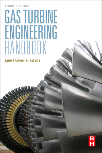
1. DESCRIZIONE DELLA MACCHINA - DESCRIPTION OF THE MACHINE1. DESCRIPTION DE LA MACHINE - BESCHREIBUNG DER MASCHINEG)I)L)M)N)P)Q)R)S)T)U)V)Z)Y)K)Griffe di bloccaggioTorretta integralePistoletta di gonfiaggioBraccio operantePalo orizzontalePalo verticaleAlimentazione ariaStallonatoreAppoggi ruotaLeva alzatalloniPedale comando stallonatorePedale comando griffePedale comando invertitorePiatto autocentranteLeva ounting headAirline gaugeMounting barHorizontal armVertical armAir supplyBead breakerWheel supportBead lifting leverBead breaker control pedalClamp control pedalReverser control pedalTurntableLocking leverPGIQYRSZVUG) Mors de blocageI) Tête de montageL) Pistolet de gonflageM) Barre de montageN) Bras horizontalP) Bras verticalQ) Raccord air compriméR) DétalonneurS) Supports de roueT) Levier démonte-pneusU) Pédale de commande du détalonneurV) Pédale de commande des morsZ) Pédale de commande de l’inverseurY) Plateau à centrage automatiqueK) Levier de blocageTG)I)L)M)N)P)Q)R)S)T)U)V)Z)Y)K)6Fig. 1/ Abb. �ckblattRadanschlägeHebel zur WulstanhebungSteuerpedal AbdrückblattSteuerpedal SpannklauenSteuerpedal WendegetriebeZentriertischSperrhebel
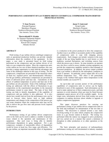
AVVERTENZE DI PERICOLO - DANGER WARNING SIGNS - AVIS DE DANGER - GEFAHRENHINWEISE3001104300541630057423005413Cod. 300004830054143005410Cod. 30007993005415Fig. 27
2. GENERALITÀ2.1 DESTINAZIONE D’USO. Lo smontagomme semi-automatico è stato progettato e realizzato esclusivamente per lo smontaggio e il montaggiodei pneumatici dai/sui cerchi con dimensioni da 10" a 24" e diametro max. 1100 mm.Qualsiasi altro uso è da considerarsi improprio e quindi irragionevole E’ vietato utilizzare la macchina per: raddrizzare cerchi stallonare pneumatici ancora gonfi o sporchi, rimuovere cerchiettiruota In particolare IL COSTRUTTORE non può essere considerata responsabile per eventuali danni causati da usi nonesplicati in questo manuale e quindi impropri, erronei ed irragionevoli.2. GENERAL2.1 INTENDED USE The semi-automatic tyre changer has been designed and manufactured exclusively for removing and mountingtyres from/onto rims from 10" to 24" and a maximum diameter of 1100 mm.Any other use is to be considered incorrect and unreasonable. It is forbidden to use the machine for straightening rims, breaking beads of still inflated or dirty tyres, removing bead wires. In particular The Manufacturer cannot be held responsible for any damage caused through the use of this tyre changer forpurposes other than those specified in this manual, and therefore inappropriate, incorrect and unreasonable.2. GENERALITES2.1 DESTINATION Le démonte-pneus semi-automatique a été projeté et réalisé exclusivement pour le démontage et le montage despneus des/sur les jantes avec dimensions de 10" à 24" et diamètre max de 1100 mm.Toute autre utilisation doit être considérée impropre et donc irraisonnée. Il est interdit d’utiliser la machine pour: redresser les jantes, décoller de pneus encore gonflés ou sales, enlever les tringlesdu talon. Le constructeur ne peut pas être considérée responsable de dommages éventuels causés par des utilisations qui nesont pas expliquées dans ce manuel et par conséquent impropres et incorrectes.2.ALLGEMEINES2.1VERWENDUNGSZWECKDas halbautomatische Reifenmontiergerät wurde ausschließlich zum Ab- und Neumontieren von Reifen von/auf Felgen geschaffen von 10"bis 24" und einem Durchmesser bis zu 1100 mm,.Jede anderweitige Verwendung ist unsachgemäß und deshalb unzulässig !Die Maschine zum Felgenrichten oder zum Wulstabdrücken von noch aufgepumpten oder schmutzigen Reifen NICHT benutzen. Es istauch verboten, die Maschine zum Entfernen von Wulstkerne zu benutzen.Der Hersteller haftet daher nicht, wenn durch Verwendungen, die in diesem Handbuch nicht vorgesehen und deshalb unsachgemäß, falschund unzulässig sind, Schäden entstehen.8
2.2 NORME GENERALI DI SICUREZZA.L’uso dello smontagomme è consentito solo ed esclusivamente a personale esperto, appositamenteaddestrato ed autorizzato. Ogni e qualsiasi manomissione o modifica dell’apparecchiatura non preventivamente autorizzate dal costruttoresollevano quest’ultimo da ogni responsabilità per danni derivati o riferibili agli atti suddetti. La rimozione o manomissione dei dispositivi di sicurezza comporta la decadenza immediata della garanzia e laviolazione delle Norme Europee per la Sicurezza. Lo smontagomme è corredato di decalcomanie di istruzione ed avvertenze progettate e realizzate per durare nel tempo.Qualora venissero danneggiate o distrutte, l'utente deve richiederle subito al costruttore utilizzando i codici di pag.82.2 GENERAL SAFETY PRECAUTIONSThe tyre changer may only be used by specially trained and authorized expert personnel. Any tampering or modification to the equipment carried out without the manufacturer’s prior authorization will free him fromall responsibility for damage caused directly or indirectly by the above actions. Removing or tampering with safety devices immediately invalidates the guarantee and is in contravention of EuropeanSafety Standards. The tyre changer comes complete with instruction and warning transfers which are designed to be long-lasting.If they should for any reason be damaged or destroyed, please ask immediately for replacements from the manufacturerusing the codes given on page 8.2.2 NORMES GENERALES DE SECURITEL’utilisation du démonte-pneus est permise exclusivement à du personnel spécialisé, expressémentformé et autorisé. Le constructeur n’est pas responsable des dommages causés par les appareils qui ont été modifiés sans son autorisationpréalable. La garantie est immédiatement nulle si des modifications ou des transformations sont apportées aux dispositifs desécurité; celles-ci sont une violation des normes européennes pour la sécurité. Le démonte-pneus est équipé de décalcomanies d’instructions et d’avis de danger, projetées et réalisées pour durer dans letemps. Si elles sont endommagées ou détruites, l’utilisateur doit les demander immédiatement au constructeur en utilisantles codes de la page 8.2.2ALLGEMEINE SICHERHEITSNORMENDie Verwendung des Reifenmontiergerätes ist nur Personen gestattet, die entsprechende Erfahrung haben,eingewiesen worden und zum Gebrauch befugt sind.-Falls Veränderungen oder Eingriffe auf dem Gerät vorgenommen werden, die vom Hersteller nicht zuvor bewilligt worden sind, haftetdieser nicht für Schäden, die auf diese zurückzuführen sind.-Die Entfernung oder Veränderung von Sicherheitsvorrichtungen bewirkt den sofortigen Verfall der Garantie und stellt eine Verletzung derEuropäischen Sicherheitsnormen dar.-Auf dem Reifenmontiergerät wurden Klebeetiketten mit Anweisungen und Warnungen angebracht, durch deren Beachtung die Lebensdauerdes Gerätes verlängert werden kann.Werden diese beschädigt oder entfernt, müssen sie sofort beim Hersteller unter Angabe der Bestell-Nummern von Seite 8 angefordert werden9
3. TRASPORTO Lo smontagomme deve essere trasportato nell'imballo originale e mantenuto nella posizione indicata sull'imballo stesso. Lo spostamento della macchina imballata deve essere effettuato inforcando con un carrello elevatore di adeguatecapacità.3. TRANSPORT The tyre changer must be transported in its original packaging and kept in the position shown on the package itself. The packaged machine may be moved by means of a fork lift truck of suitable capacity.3. TRANSPORT Le démonte-pneus doit être transporté dans son emballage et maintenu dans la position indiquée sur l’emballage même. La machine emballée doit être déplacée sur les fourches d’un chariot élévateur d’une capacité appropriée.3. TRANSPORTDas Reifenmontiergerät darf nur in seinerOriginalverpackung und in der auf der Verpackungangegebenen Position transportiert werden.Die verpackte Maschine darf nur mit einem dazugeeigneten Gabelstapler angehoben und transportiert werden.4. DISIMBALLOTogliere il cartone di protezione e il sacchetto in nylonAssicurarsi dell’integrità dell’apparecchio controllando che non vi siano parti visibilmente danneggiate omancanti facendo riferimento alla fig. 1In caso di dubbio non utilizzare la macchina e rivolgersi al proprio rivenditore.4. UNPACKINGRemove the protective cardboard and the nylon bag.Check that the equipment is in perfect condition, making sure that no parts are damaged or missing. Use fig. 1 forreference.If in doubt do not use the machine and contact your retailer.4. DEBALLAGEEnlever le carton de protection et le sac en nylon.Contrôler qu’il n’y ait pas de parties visiblement endommagées ou manquantes en se référant à la figure 1.En cas de doute, ne pas utiliser la machine et s’adresser au revendeur autorisé.4. AUSPACKEN DER MASCHINESchutzkarton und Plastikbeutel entfernen.Kontrollieren, ob das Gerät intakt ist, ob keine sichtbaren Beschädigungen vorhanden sind oder Teile fehlen, siehe dazu Abb.1.Im Zweifelsfalle die Maschine nicht benützen und den Verkäufer benachrichtigen.10
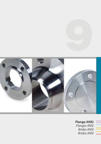
5. INSTALLAZIONE5.1 SPAZIO NECESSARIOAl momento della scelta del luogo di installazione, è necessario osservare le normative vigenti perla sicurezza sul lavoro Lo smontagomme semi-automatico, necessita di collegamenti con la rete elettrica e con l’impianto di aria compressa.E’ perciò opportuno installare la macchina in prossimità di tali fonti energetiche. Inoltre, sul luogo prescelto per l’installazione, devono essere disponibili almeno gli spazi indicati dalle fig. 4 - 4/A perpermettere il regolare funzionamento di tutte le sue parti senza alcuna limitazione. Se la macchina viene installata all'aperto è necessario che sia protetta da una tettoia.Nel caso lo smontagomme sia del tipo a motore elettrico è proibito l'uso in atmosfere esplosive a meno chenon si tratti di una apposita versione.5. INSTALLATION5.1 SPACE REQUIREDWhen choosing the place of installation be sure that it complies with current safety at work regulations. The semi-automatic tyre changer must be connected to the mains electric power supply and the compressed air system.It is therefore advisable to install the machine near these power sources. The place of installation must also provide at least the space shown in fig. 4 - 4/A so as to allow all parts of the machine tooperate correctly and without any restriction. If the machine is installed outside it must be protected by a lean-to.1460/1750The tyre changer with electric motor cannot be used in explosive atmospheres, unless it is a proper version.097910/1120Fig. 411
5. INSTALLATION5.1 EMPLACEMENT NECESSAIREAu moment du choix du lieu d’installation, observer les normes en vigueur pour la sécurité du travail. Le démonte-pneus semi-automatique devra être raccordé au réseau électrique et à l’installation d’air comprimé. Il faudradonc en tenir compte pour le choix de l’emplacement. De plus, dans le lieu d’installation il faudra les espaces nécessaires pour permettre le fonctionnement régulier de toutes lesparties du démonte-pneus, sans aucune limitation (voir fig. 4 - 4/A). Si la machine doit être installée en plein air, elle devra être protégée par un abri.Si le démonte-pneus est du type à moteur électrique, son utilisation est interdite près de matières explosives,à moins qu’il ne s’agisse d’une version appropriée.5.5.1INSTALLATIONPLATZBEDARFBei der Wahl des Aufstellungsortes müssen die gültigen Bestimmungen zur Sicherheit am Arbeitsplatz beachtet werden.Das halbautomatische Reifenmontiergerät benötigt Anschlüsse an das Stromnetz und an die Druckluftzufuhr. Deshalb ist es ratsam, dieMaschine in der Nähe dieser Energiequellen aufzustellen.Zudem muss am gewählten Installationsort mindestens soviel Platz vorhanden sein, wie in Abb. 4 - 4/A angegeben ist, so daß der Betrieballer Maschinenteile problemlos eingestellt werden kann.Wird die Maschine im Freien aufgestellt, muß sie durch ein Dach geschützt werden.1460/1750Falls das Reifenmontiergerät einen elektrischen Motor aufweist, darf es nicht in Räumen mit Explosionsgefahr verwendet werden, außer wenn es um eine geeignete Ausführung handelt.097910/1120Fig. 412
5.2 POSIZIONAMENTO E MONTAGGIO COMPONENTI Svitare le viti di fissaggio al pallet e posizionare lo smontagomme sul pavimento. Svitare le quattro viti dalla carcassa, posizionare il palo verticale nell’apposita sede e riavvitare le viti . (Fig. 5/a).ATTENZIONE: Prima di effettuare gli allacciamenti alle fonti energetiche accertarsi che le caratteristiche dei propriimpianti corrispondano a quelle richieste dalla macchina. Collegare la macchina alla rete dell’aria compressa.(Fig. 5/c) Premere il pedale dello stallonatore per poter togliere il gancio dall’asta del cilindro. (Fig. 5/d). Montare il braccio stallonatore come indicato in fig. 5/e:- Inserire il braccio (a) nella sede, infilare la vite nel foro e avvitare il dado SENZA STRINGERE.- Inserire il perno orientabile (b) nel foro sul braccio e fare passare l’asta del cilindro nel foro del perno stesso.Avvitare i due dadi SENZA STRINGERE.- Inserire la molla agganciandola nei punti indicati. Avvitare la vite del braccio stallonatore come indicato in fig. 5/f Avvitare il dado come indicato in fig. 5/g.5.2 POSITIONING AND PARTS ASSEMBLY Unscrew the pallet fixing screws and set the tyre-changer on the floor. Unscrew the 4 screws from the body, set the vertical arm into the proper seat and fix the screws again (Fig. 5/a)Remarks:Before connecting all the power sources ALWAYS check your installations.They must exactly correspond to those requested by the machine. Connect the machine to the compressed air network (Fig. 5/c) Press the bead breaker’s pedal in order to release the hook from the cylinder’s shaft (Fig. 5/d) Mount the bead breaker arm as shown by fig. 5/e:- Set the arm “a” into the proper seat, set the screw into the hole and screw the nut WITHOUT TIGHTENING.- Set the pivot pin “b” into the hole on the arm and let the cylinder’s shaft pass through the pin’s hole. Screw thetwo nuts WITHOUT TIGHTENING.- Set the spring by hooking it at the indicated points. Screw the bead breaker arm’s screw as indicated in Fig. 5/f Screw two nut as indicated in Fig. 5/g.13
Fig. 5/a - Abb. 5/aFig. 5/d - Abb. 5/dFig. 5/c - Abb. 5/cFig. 5/f - Abb. 5/fFig. 5/e - Abb. 5/eFig. 5/g - Abb. 5/g14
5.2 MONTAGE Dévisser les vis de fixation de la palette et positionner le démonte-pneus au sol. Dévisser les 4 vis du bâti, positionner le bras vertical dans son siège et visser les vis de nouveau (Fig. 5/a).Remarque:Avant d’effectuer les connexions aux sources d’énergie, s’assurer TOUJOURS que les caractéristiques des installationscorrespondent à celles demandées par la machine. Connecter la machine au reseau d’air comprimé (Fig. 5/c) Appuyer sur la pédale du décolleur pour enlever le crochet de la tige du cylindre (Fig. 5/d) Monter le bras décolleur comme indiqué en fig.5/e:- Placer le bras “a” dans son siège, insérer la vis dans le trou et visser l’écrou SANS SERRER.- Insérer le pivot “b” dans le trou sur le bras et laisser passer la tige de l’axe dans le trou de l’axe même. Visser les 2 écrousSANS SERRER.- Insérer le ressort en l’accrochant aux points indiqués. Visser la vis du bras décolleur comme indiqué en fig. 5/f Visser les 2 écrous comme indiqué en fig. 5/g.5.2 MONTAGE Die Befestigungsschrauben abschrauben und das Reifenmontiergerät auf dem Boden stellen. Die 4 Schrauben vom Rahmen abschrauben, den senkrechten Arm in den dazu bestimmten Sitz stellen und die Schrauben mit demSteckschlüssel wiederschrauben (Abb. 5/a)HINWEIS:Vor der Verbindung mit den Energiequellen sich versichern, daß die Anlage den Maschinendaten entspricht. Die Maschine mit dem Druckluftnetz verbinden (Abb. 5/c) Auf das Wulstabdrückpedal drücken, um den Haken der Zylinderstange zu entfernen (Abb. 5/d) Den Wulstabdrückarm wie in Abb. 5/e einstellen:- Den Arm (a) in seinen Sitz einsetzen, die Schraube ins Loch stecken und die Mutter anschrauben OHNE FESTSPANNEN.ter- Den Drehbolzen (b) ins Loch auf dem Arm einsetzen und die Zylinderstange ins Bolzenloch durchlassen. Die 2 Mutanschrauben, OHNE FESTSPANNEN.- Die Feder einführen und sie in den gezeigneten Punkten anklinken. Die Schraube vom Wulstabdrückarm wie gezeigt in Abb. 5/f anschrauben. Die 2 Mutter wie gezeigt in Abb. 5/g anschrauben.15
Fig. 5/a - Abb. 5/aFig. 5/d - Abb. 5/dFig. 5/c - Abb. 5/cFig. 5/f - Abb. 5/fFig. 5/e - Abb. 5/eFig. 5/g - Abb. 5/g16
Montaggio e collegamento manometro Fissare la scatola manometro al palo verticale tramite leapposite viti in dotazione. Collegare il tubo al raccordo esterno posteriore alla carcassaMounting and connecting the manometerFix the manometer box to the vertical arm through the properscrews.Connect the pipe to the union at the machine backsideMontage et branchement du manomètreFixer la boîte manomètre au bras vertical moyennant les visfournies.Brancher le tuyau au raccord sur le bâti arrière.Montage und Verbindung des ManometersManometergehäuse am Vertikalausleger durch die dazu bestimmtenSchrauben befestigen.Den Rohr mit dem auf der Maschinenrückseite anwesenden Anschluss verbinden.17
5.3 MESSA IN SERVIZIOPrima di effettuare gli allacciamenti, accertarsi che le caratteristiche dei propri impianti corrispondano aquelle richieste dalla macchina. Se fosse necessario cambiare la tensione di funzionamento della macchina occorre intervenire sulla morsettiera (Cap. 14schema elettrico)Interventi sull’impianto elettrico, anche se di lieve entità, richiedono l’intervento di personaleprofessionalmente qualificato. Collegare la macchina all’impianto d’aria compressa tramite l’attacco (Q) sporgente dalla parte posteriore (fig. 6) Collegare la macchina alla rete elettrica che deve essere dotata di fusibili di linea, di una buona presa a terracome da norme vigenti e collegata ad un interruttore automatico di alimentazione (differenziale) tarato a 30 mA.NOTA: Qualora lo smontagomme venga fornito senza spina elettrica, sarà cura dell'utente montarne una(almeno 16 A)adeguata alla tensione della macchina e secondo le normative vigenti.5.3 COMMISSIONINGBefore making the connections, check that the characteristics of your systems correspond to those requiredby the machine. If you have to change the machine’s operating voltage, make the necessary adjustments to the terminal board (Chap.14)Even small jobs done on the electrical system must be carried out by professionally qualified personnel. Connect the machine to the compressed air system by means of the air connection (Q) that protrudes from the rear sectionas shown in the diagram 6. Connect the machine to the electric network, which must be provided with line fuses, a good earth plate in compliance with regulations in force and it must be connected to an automatic circuit breaker (differential) set at 30 mA.Note: Should the tyre-changer be lacking in electric plug, so the user must set one,which is at least 16 A and whichconforms to the voltage of the machine, in compliance with the regulations in force.5.3 MISE EN MARCHEAvant d’effectuer les raccordements, vérifier que les caractéristiques des installations correspondent à cellesdemandées par la machine. S’il faut changer la tension de fonctionnement de la machine, intervenir sur le bornier (voir schéma électrique Chap. 14).Les interventions sur l’installation électrique, même si elles sont peu importantes, doivent être effectuées pardu personnel qualifié. Raccorder la machine à l’installation d’air comprimé par le raccord (Q) situé à l’arrière (voir figure 6). Relier la machine au reseau électrique, qui doit être equipé de fusibles de ligne et d’une prise de terre conformément auxnormes en vigueur. De plus, il faut relier la machine à un interrupteur automatique d’alimentation (différentiel) reglé à 30 mA.NOTE: Si le demonte-pneus est dépourvu de fiche électrique, l’utilisateur devramonter une fiche qui soit proporsionnéeà la tension de la machine ( au moins 16 A) conformément aux normes en vigueur.5.3INBETRIEBNAHMEVor dem Anschluß muß überprüft werden, ob die Eigenschaften der Betriebsanlagen den von der Maschinegeforderten Werten entsprechen.-Falls die Betriebsspannung der Maschine geändert werden muß, entsprechend Schaltplan im Kap. 14 Klemmenbrett vorgehen.(Auch kleinere) Eingriffe an der elektrischen Anlage dürfen nur von Fachpersonal vorgenommen werden.-Maschine an das Druckluftnetz anschließen, hierzu den Anschlußstutzen (Q) verwenden, der gemäß Abbildung hinten hervorsteht.Maschine vorschriftsgemäß an das Stromnetz anschließen. Das Stromnetz muß mit Schmelzsicherungen sowie mit einem gutenErdschluß versehen werden. Dazu muß die Maschine an einen selbstätigen 30mA geeichten Ausschalter (Differential) verbindet werden.WICHTIG:Wenn das Reifenmontiergerät ohne Steckdose geliefert wird, muß der Verbraucher mindestens eine 16A Steckdoseanschließen. Diese muß an die Spannung der Maschine angemessen und gemäß der gültigen Bestimmungen sein.18
5.4 TEST DI FUNZIONAMENTO Premendo il pedale (Z) il piatto autocentrante (Y) deve ruotare in senso orario. Spingendo verso l'alto il pedale il piattoautocentrante (Y) deve ruotare in senso antiorario.N.B:Se il piatto girasse in senso opposto a quello indicato è necessario invertire due fili sulla spina trifase Premendo il pedale (U) si aziona lo stallonatore (R); rilasciando il pedale lo stallonatore ritorna nella posizione originale Premendo il pedale (V) si aprono le quattro griffe di bloccaggio (G); premendo nuovamente si chiudono. Premendo il grilletto della pistoletta di gonfiaggio esce aria dalla testina.5.4 OPERATING TESTS When pedal (Z) is pressed down the turntable (Y) should turn in a clockwise direction.When pedal is pulled up the turntableshould turn in an anticlockwise direction.Note: If the turntable turns in the opposite direction t
1. BESCHREIBUNG DER MASCHINE Seite 6 Gefahrenhinweise und Verbote Seite 7 2.ALLGEMEINES Seite 8 2.1 VerwendungszweckSeite 8 2.2 Allgemeine Sicherheitsvorschriften Seite 9 3.TRANSPORT Seite 10 4. AUSPACKEN DER MASCHINE Seite 10 5.INSTALLATION Seite 11 5.1