Transcription
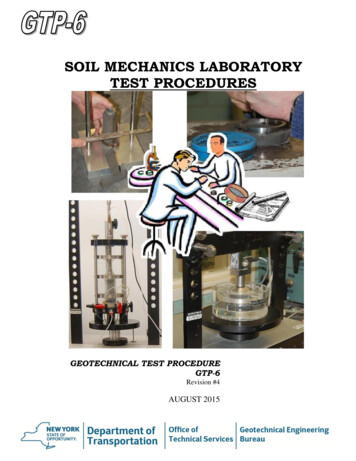
SOIL MECHANICS LABORATORYTEST PROCEDURESGEOTECHNICAL TEST PROCEDUREGTP-6Revision #4AUGUST 2015
GEOTECHNICAL TEST PROCEDURE:SOIL MECHANICS LABORATORY TEST PROCEDURESGTP-6Revision #4STATE OF NEW YORKDEPARTMENT OF TRANSPORTATIONGEOTECHNICAL ENGINEERING BUREAUAUGUST 2015EB 15-025Page 1 of 81
TABLE OF CONTENTSI.II.III.PREFACE .5GENERAL .6A.Standard Procedure for the Processing of Soil Samples in theSoil Mechanics Laboratory .61.Introduction .62.Undisturbed Sample Procedures .63.Jar Samples .94.General Procedures .11B.Standard Procedure for Fabricating Rubber Membranes for use in theSoil Mechanics Laboratory .121.Scope .122.Summary of Method .123.Materials and Apparatus .124.Preparation and Maintenance .135.Fabrication Procedure .13C.Standard Procedure for TACT Stand Calibration .161.Start Up .162.Station Preparation .163.Station Exercise .164.Calibration.16SOIL TEST .18A.Standard Test Method for the Unconsolidated-Undrained StrengthTesting of Soils .181.Scope .182.Applicable Documents .183.Terminology .184.Summary of Method .185.Significance and Use.186.Apparatus .187.Sampling .198.Specimen Preparation .199.Procedure .1910.Calculations.2011.Report .21B.Standard Test Method for the Consolidated-Undrained StrengthTesting of Soils .221.Scope .222.Applicable Documents .223.Terminology .224.Summary of Method .225.Significance and Use.226.Apparatus .227.Sampling .238.Specimen Preparation .23EB 15-025Page 2 of 81
C.D.E.F.EB 15-0259.Procedure .2410.Calculations.2511.Report .26Standard Test Method for the Unconsolidated-Undrained Strength with PorePressure of Soils .271.Scope .272.Applicable Documents .273.Terminology .274.Summary of Method .275.Significance and Use.276.Apparatus .277.Sampling .288.Specimen Preparation .289.Procedure .2910.Data Reduction.3011.Report .30Standard Test Method for the Laboratory Determination of Moisture Contentof Soils .311.Scope .312.Definition .313.Apparatus .314.Procedure .315.Calculation .31Standard Test Method for the One Dimensional Consolidation Testing of Soils .331.Scope .332.Applicable Documents .333.Terminology .334.Summary of Method .335.Significance and Use.336.Apparatus .347.Sampling .348.Specimen Preparation .359.Procedure .3510.Calculations.3611.TACT Procedure .3912.Report .40Standard Test Method for the Soils Block Permeability Test .411.Scope .412.Significance and Use.413.Summary of Method .414.Apparatus .415.Test Procedure .426.Calculations.447.Report .45Page 3 of 81
IV.GEOTEXTILE AND RELATED PRODUCTS TESTS .52A.Standard Test Method for Testing Prefabricated Wick Drains in theCrimped Condition .521.Scope .522.Introduction .523.Apparatus .524.Test Procedure .535.Calculations.546.Report .55B.Standard Test Method for the Wick Drain Consolidation Test .571.Scope .572.Significance and Use.573.Apparatus .574.Test Preparation .595.Test Procedure .616.Test Completion .627.Computations (Form SM-455).638.Test Soil Remolding Procedure .66C.Standard Test Method for Geotextile Soil Retention Test .721.Scope .722.Applicable Documents .723.Summary of Method .724.Apparatus .725.Specimen Selection and Preparation .736.Procedure .737.Calculations.748.Report .759.Precision .76D.Standard Test Method for Long-Term Geotextile Flow Test .791.Scope .792.Summary of Method .793.Apparatus .794.Test Preparation .795.Procedure .796.Report .80APPENDIX .81A.Test Results . A-1EB 15-025Page 4 of 81
I. PREFACEThe purpose of this manual is to present the geotechnical test methods used by the SoilMechanics Laboratory of the New York State Department of Transportation's GeotechnicalEngineering Bureau. The intent is to present the mechanics of performing each test, notthe theory behind the test.The triaxial test procedures have been developed from those which are described in SoilTesting for Engineers by T. W. Lambe and The Measurement of Soil Properties in theTriaxial Test by A. W. Bishop and D. J. Henkel. The consolidation test procedures havebeen developed from those in Lambe's book.Other methods, such as those related to geotextiles, block permeability, and membranefabrication, are relatively new areas in the geotechnical field. The methods and proceduresincluded have essentially been developed, along with the equipment, by the GeotechnicalEngineering Bureau.In some cases it has been necessary to make modifications to existing methods in order toaccommodate the conditions and equipment in the Soil Mechanics Laboratory, along withthe properties of New York State soils.EB 15-025Page 5 of 81
II. GENERALA.STANDARD PROCEDURE FOR THE PROCESSING OF SOIL SAMPLES INTHE SOIL MECHANICS LABORATORY1.Introduction1.1The following procedures are intended for the orderly and accurate handlingof disturbed and undisturbed samples received in the Soil MechanicsLaboratory.2.Undisturbed Sample Procedures2.1Log-In Procedure2.1.1 Note the manner in which the tubes were shipped. If they were nottransported vertically in a proper rack, or if they were subject tofreezing weather, notify the laboratory supervisor. Transport thetubes into the lab using a tube rack. Handle tubes with care at alltimes.2.1.2 Arrange tubes in order of hole number and tube number. Assign ashelf number to all of the tubes using the shelf listings. Allinformation (PIN, project name, drill hole number, tube number,depth, shelf number and number of tubes) must be ready to enter attime of log-in.2.1.3 Enter password to access first menu. Menu I will appear as follows:MENU IEND PROGRAMJAR SAMPLESTUBE SAMPLESROCK CORE SAMPLESEND OF THE MONTH TOTALSSEARCH FOR SAMPLESARCHIVE RECORDSUse the down arrow key to select TUBE SAMPLES and pressENTER. The next menu will appear. Select the LOG-IN NEWSAMPLES option. All information may be entered on the nextscreen. When all information is entered, select the ALL CORRECToption to advance to the next screen. On this screen, enter the drillhole number and number of tubes in the hole. Advance to the nextscreen and enter the tube number, depth and shelf number. Theinformation will be stored and 3 copies of the information will beprinted. Send one copy to the Highway Design and ConstructionSection, one copy to the Structures Foundation Section and one copyis filed in PIN order in the Laboratory Samples Received notebook.EB 15-025Page 6 of 81
2.22.3EB 15-025X-Ray Preparation2.2.1 Remove the top and bottom plastic caps. Remove and discard thefiller material using a spatula, taking care not to push the wax intosoil. Inspect the tubes for any damage and fill out Form No. SM-403,“Undisturbed Sample Evaluation”.2.2.2 Measure the distance from each end of the tube to the wax and addthese together. This measurement will be used for the top of soil lineof the scale on From SM-288b, “Undisturbed Sample Log”. Checkthe length of each tube and make necessary adjustments to the scale.Fill out a sample log form for each tube including all pertinentinformation.2.2.3 Mark the outside of each tube indicating the location of the top of thesoil. Indicate PIN, hole number and tube number on the caps. Replaceand tape the plastic capes. Remove tape from labels on tubes. Tapelead markers 90 apart over the top of the soil line on the outside ofthe tube. Mark the lead pellets A and B respectively.2.2.4 Enter all pertinent information in the lab’s x-ray book. Write the xray number on each corresponding tube with a permanent marker,keeping in sequence with the last number in the x-ray log book.2.2.5 Indicate on a piece of memorandum paper all of the informationpertaining to the tube samples. Send it with the tube samples to theMaterials Testing Laboratory’s X-Ray Department. If the tubescannot be x-rayed immediately, inquire as to when they can be andstore them in the moist room.X-Ray Completion2.3.1 After receiving the x-rays, fill out (on small gummed labels) the holenumber, tube number, and either “A” or “B” to identify the exposure.Place these labels in the top left corner of the x-ray. Do not cover thecode numbers or any part of the x-ray.2.3.2 Place the x-rays into appropriate envelope. Indicate on the envelopethe PIN, job name, hole number, tube number, and x-ray number.e.g. 5935.56.101Oak PointDNB-1Tube No. XXX-ray No. XXX2.3.3 After the tubes have been x-rayed, place them on the assigned shelfin the moist room.2.3.4 Notify the Laboratory Supervisor and the Supervisor of DrillingOperations that the x-rays are ready for review. Any disturbance seenduring the review of the x-rays must be entered on Form SM-403.2.3.5 Because the x-rays become faded over a period of time, a picture ofeach x-ray must be taken to ensure a permanent record. Mount the 35mm camera either on the copying stand or the tripod. Place both x rays from each tube on the light table and photograph.2.3.5.1 Place the exposed film in its canister and send to reproductionwith the label specifying “negatives only”. Record in the x -raylog book which tubes have been photographed.Page 7 of 81
2.4EB 15-0252.3.6 When the negatives return, cut them apart and mount them in 35 mmslide frames. Put these in the appropriate file.Profiling Tubes2.4.1 Prepare the following for profiling tubes:2.4.1.1 Tare out scale.2.4.1.2 Number tares with PIN, tube and hole numbers.2.4.1.3 Arrange tubes on lab table or cart in order of tube number.2.4.1.4 Set up camera.2.4.1.5 Have x-rays and partially prepared tube log sheets and tubecondition sheets ready.2.4.1.6 Fill out Moisture/ Density sheets with appropriateinformation.2.4.1.7 Make sure cutting wire, metal screed, ring and plate are clean.2.4.2 Notify Design Engineer that you are ready to begin profiling tubes.When ready, jack enough soil out to remove the top wax. Measurethickness of the wax and record on log sheet.2.4.3 Take a sample for the purpose of determining density, moisturecontent and visual description. After removing from the density ring,the sample is cut vertically through the middle, opened and placed ina tare. This is immediately weighed and the mass recorded on theMoisture Content/Wet Density sheets, and placed in an oven at230 9 F (110 5 C) for a minimum of 16 hrs.NOTE: Do not touch soil in tare once it has been weighed asthis will affect the test results.2.4.4 Photograph the sample making sure the PIN, hole and tube numbersare visible. Make a visual description of the soil and record on tubelog in appropriate depth area. Draw a small circle in test columnacross from visual description for Moisture Content and Densityresults to be entered.2.4.5 Remove tube from the jack and measure distance from bottom of tubeto the bottom wax. Record on tube log, measuring from the TOPlocation on the log. Replace and re-tape the caps on tube and returnto moist room.2.4.6 After samples have dried for 16 hours, remove from the oven. Tareout the scale and weigh the sample. Record on the Moisture/ Densitysheet. Compute the Moisture Content using:Page 8 of 81
Equation (1)Wwx 100 Moisture ContentWswhere:W w Mass of Water in the SpecimenW s Mass of Dry Soil2.4.6.1 Compute the wet density using:Equation (2)WT x K Wet Density ( T )where:K Density Constant for Ring, 1.01 (for lb/ft 3 )or 16.18 (for kg/m 3 )W T Total Wet Mass of the Specimen3.2.4.7 After computations have been checked by Section Supervisor, entervalues in appropriate areas on individual tube log sheets. Prepareundisturbed sample summary log sheet with all appropriateinformation. Have the summary log reviewed and signed by the SoilsEngineering Laboratory Supervisor.2.4.8 After summary log has been signed by Laboratory Supervisor, havetwo copies made. Send one copy to the project file and one copy tothe Regional Geotechnical Engineer.2.4.9 Complete the Tube Condition sheet, make 2 copies and send both toSupervisor of Drilling Operations. Staple original to tube log sheetsand place in appropriate basket on lab table. All original data sheetsare kept in the laboratory.2.4.10 Prepare a folder with PIN and hole number on outside cover. Placeoriginal summary log in folder and file by PIN in Undisturbed TestData file drawers.Jar Samples3.1Log-In Procedure3.1.1 Note the manner in which they were received. If boxes are inunsuitable condition for proper and neat storage they must bereplaced and relabeled.3.1.2 Arrange boxes in order of PIN and drill hole number. Assign eachbox a shelf number using the shelf listings for jar samples. PIN, jobname, region, county, number of drill holes, number of jars, numberEB 15-025Page 9 of 81
of boxes and shelf numbers must be ready to enter at time of log-in.3.1.2.1 Enter password to access first menu. Select the JARSAMPLES option and press ENTER. Select LOG-IN NEWSAMPLES option on the next screen. Information about thejar samples is entered on the following screens. Theinformation is stored and 3 copies printed out. One copy issent to the Highway Design and Construction Section, onecopy to the Structures Foundation Section, and one copy isfiled in PIN order in the Laboratory Samples Receivednotebook.3.2 Requested Moisture Contents3.2.1 Moisture content determinations may often be requested on jarsamples. Fill out the Moisture Content Sheet with all availableinformation from jars. Write your initials and date in upper righthand corner. Number tares with hole and jar number for each sample.Tare out scale.3.2.2 Empty the contents of the jar into a large open container. Remove arepresentative portion of the sample and place it in a tare. Do not useall of the sample for a moisture content determination as the samplemay be needed for other tests. Weigh the sample immediately andrecord the mass on the Moisture Content sheet.NOTE: Do not touch soil in tare once it has been weighed asthis will affect the test results.3.2.3 Place tares in oven at 230 9 F (110 5 C) to dry for a minimum of16 hours. After drying, remove tares from oven. Tare out scale andweigh each sample. Record the mass and compute the moisturecontent using Equation 1. Enter the date and your initials in the upperright hand corner. Have the computations checked by the SectionSupervisor.3.2.4 Distribute copies of results as directed by requester.3.2.5 Total number of moisture contents must be recorded and reported onthe end of the month totals.3.2.6 Store boxes in appropriate shelf slots in the cage in the basement ofBuilding 7A.3.3Test Request Procedure for Jar Samples3.3.1 Check laboratory "Samples Received" log book to determine whetherjars have been received or emptied. Make sure the Design Engineerhas checked jars and knows the soil type. Also, check to make surevisuals and moisture contents have been done on all jars at somepoint. Determine if there is sufficient material in each jar for the testrequest and if material is appropriate for the test requested.3.3.2 Enter test request information on Form SM-205 b. Write date,Project, PIN, hole and sample numbers and tests requested on theform.EB 15-025Page 10 of 81
4.3.3.3 Make a copy of Form SM-205 b and send it to the General SoilsLaboratory with the jar samples.3.3.4 The number of samples sent to the General Soils Laboratory must berecorded. Log into the computer and select "Search for Samples"option. Enter the region number and PIN. Move the cursor down tothe hole number desired and then enter the number of jars sent to theGeneral Soils Lab for each test.3.3.5 Fill out the appropriate summary sheet, and after all results arereceived and sheet is completed, file it in a folder under its PIN in thedisturbed test data file drawer. Bring all test result forms to theEngineer requesting the tests.3.4Procedure for Emptying Shelby Tubes or Brass Liners3.4.1 Determine which tubes are to be emptied by circulating an inventorylist through each Design Section and the Highway Design andConstruction Section. Obtain log sheet for appropriate PIN and holenumbers.3.4.1.1 Get x-rays from drawer;3.4.1.2 Find status of the sample on the inventory sheet;3.4.1.3 Obtain tubes form the moist room;3.4.1.4 Do visual and bottom wax measurement as the tube isemptied;3.4.1.5 Write in the visual in the appropriate location on the samplelog sheet;3.4.1.6 Indicate the date emptied on the individual tube log sheet;3.4.1.7 Return log sheet and x-rays to their appropriate location;3.4.1.8 Delete emptied samples from computer and print out a newinventory list.3.5Procedure for Emptying Jars3.5.1 Determine which jars are to be emptied by circulating an inventorylist of jars through each Design Section, the Highway Design andConstruction Section and the Regional Geotechnical Unit.3.5.1.1 Empty jars into large trash barrel downstairs;3.5.1.2 Bring jars to the Jar Wash Room downstairs to be washed andreused;3.5.1.3 Delete samples from computer and print out a new inventorylist.3.5.2 Obtain a list, by Region, of projects for which samples were disposedof. The Soils Engineering Laboratory Supervisor will prepare a letterto the Region listing the above information.General Procedures4.1Turn off scales at night;4.2Keep x-ray light off when not in use;4.3Return all tubes to moist room;4.4Make sure oven is on or off as needed.EB 15-025Page 11 of 81
B.STANDARD PROCEDURE FOR FABRICATING RUBBER MEMBRANESFOR USE IN THE SOIL MECHANICS LABORATORY1.Scope1. 1 There is a need in the Soil Mechanics Laboratory for rubber membranes thathave specific characteristics of strength, durability, and elasticity. Themembrane must be sensitive so as not to deform the soil sample onto whichit is applied, e.g. the square corners on a cubical sample.It is alsoimportant that a membrane for a triaxial test not add any significant strengthto the soil.1.2There are many benefits to fabricating one’s own membranes in thelaboratory. Primarily, a constant supply can be readily available and madeto the desired specifications.It is also very economical, as custommade membranes can be quite expensive when purchased from amanufacturer.2.Summary of Method2.1A mandrel of the desired shape is dipped into a saturated solution of calciumnitrate and methanol and then placed in a temperature regulated oven tocure. The mandrel is then dipped into a container of liquid latex for apredetermined time and then removed and placed back in the oven to allowthe latex to cure. The membrane is then trimmed from the mandrel, soakedin water as a final curing stage, dried and trimmed.3.Materials and Apparatus3.1Latex – the liquid latex shall be Vultex Formulation 1-V-731-A. The properviscosity of the liquid latex is achieved by the addition of distilled water.3.2Coagulant – The coagulant shall be a saturated solution of four (4) partsmethanol to one (1) part powdered calcium nitrate.3.3Storage containers – Two (2) storage containers are required to store theliquid latex and the coagulant. They shall be Lucite cylinders, 5.5 in. (139.7mm) in diameter by 13.5 in. (342.9 mm) high, each with a stationary base.The top must be able to be sealed air-tight.3.4Mandrels – The mandrels, for dipping into the coagulant and liquid latex,shall conform in shape to the soil sample to be tested, the top stone cap andthe bottom stone pedestal over which the finished membrane will be fitted.3.4.1 The mandrel used to fabricate membranes used for the 2 in. (50.8mm) cube block permeability test shall be made of polyurethanecoated cherry wood and shall have a handle at the top.3.4.2 Two (2) mandrels are used to fabricate membranes used for the 3.375in. (85.72 mm) full diameter triaxial test. They shall be polishedstainless steel cylinders (modified Shelby Tubes), 3.5 in.
The purpose of this manual is to present the geotechnical test methods used by the Soil Mechanics Laboratory of the New York State Department of Transportation's Geotechnical Engineering Bureau. The intent is to present the mechanics

