Transcription
AutooCADD 20166 Prevview GuideeDesign evvery detail witth Autodesk AutoCAD sooftware, one of the world’’s leading CADD applications.Create stuunning 2D and 3D designs with robust toolstthat cann produce almmost any shappe imaginablee.Share youur work with confidencecussing TrustedDDWG technoology, the original and moost accurate wway tostore and exchange deesign data. Speed detailingg and documeentation workk with tools bbuilt to helpeandd maximize prroductivity. Connect your wworkflow andd collaborate with colleaguesincrease efficiencyusing inteegrated desktop, cloud, and mobile soluutions. AutoCCAD delivers tthe quality yoou can expect.1
Table of ContentsUser interface . 3File tabs . 3Layouts . 4Status bar. 4Ribbon . 5Help . 5Documentation . 6Revision clouds . 6Dimensioning . 8Text. 10Geometric Center object snap . 11Isometric line grid . 12Move/copy enhancement . 12Property preview . 12Command preview . 13Selection highlighting color . 13Xref enhancements . 13PDF enhancements . 14Plot dialog box . 17Design . 18Section object . 18Point clouds . 19Render engine . 24Coordination model . 28BIM 360 add-in for AutoCAD enhancements . 29Installation and configuration . 31Improved graphics . 31System Variable Monitor. 32Security . 33Single service pack . 352
User innterfaceFile tabbsThe New TabT drawing file tab has been renamedd to Start and remains perssistent as youu create and oopenadditional drawings. Thhe NEWTABMMODE systemm variable has been renamed to STARTMMODE. When setto 0 the Start tab is not displayed.y to controol whether th e Start tab is displayed forr installA new deployment opttion enables youents.deploymeYou can presspCtrl Homme or use thee new GOTOSSTART commaand to switchh focus from tthe currentdrawing to the Start taab. The new CLOSEALLOTHCHER commandd offers commmand line acccess to close aallthe open drawings exccept the one in focus.The Tip off the Day on thet Learn pagge is updated every 24 houurs. You can uuse the arrowws to cycle thrroughmultiple tipst one at a timetand the tips can now contain inlinee images.3
LayoutssLayouts now support dragdand dropp to move or copyclayouts to positions tthat are hidden in the oveerflowe selected layoouts to the rigght or left ed ge of the layoout tabs theyy automaticallymenu. As you drag theouts into the proper positiion.scroll, enaabling you to drop the layoNew conttrols in the rigght-click menu enable you to dock the llayout tabs inn line with thee status bar oorabove it.Status barbThe Status bar can noww automatically wrap ontoo two rows w hen there aree more icons than can fit into asingle roww. At any given time, the modelmtab andd at least one layout tab arre always dispplayed.Isolate Obbjects and Locck UI have beeen added to the Status baar customization menu.The Lock User Interface tool on the Status bar ennables you too check and uncheck multiple UI elements atone time instead of having to reopeen the flyout each time. Cllick the icon tto enable or ddisable UI locking.4
RibbonnThe new GALLERYVIEWGW system variable enables you to controol whether Ribbon galleriees are displayyed.When GALLERYVIEW iss set to 1, thuumbnail preview images off blocks as weell as dimensiions, mleaderrs,and tables display in thhe Ribbon.When it’s set to 0, the Insert dialog box is displayyed to accesss Blocks and ttraditional styyle lists areeader, and taable styles.displayed in the Ribbon to access diimension, mleHelpImprovemments to the AutoCADAHelpp system makke it easier too access relevant Help conttent and tools.Single siggn-onYou are automatically signed into HelpH documenntation when you sign intoo your A360 aaccount frommentation ennables you to Like a Help toopic.AutoCAD and vice-verssa. Signing intto Help docum5
UI Finderu click on the Find link for a tool in the Help windoww, an animatedd arrow pointts to the locationWhen youof that tool in the Quicck access toollbar and Ribbon. In AutoCAAD 2016 this functionalityy has beenhe Status bar and application menu.extended to include thn the Status barb but not cuurrently visibl e, the UI Findder will point to theIf an icon is available inb icon.Customizaation Status barDocummentationRevisioon cloudsThe Revision Cloud toool is enhancedd in AutoCAD 2016 to provvide more flexibility. It is aaccessible from theel and includees three methods of creatioon: rectangullar, polygonal, and freehannd—Annotate Ribbon panein addition to the Command line opption to selectt an object. TThe last used ccreation method isered the next time the commmand is run. You can set your own default creationn method usinngremembethe REVCLLOUDCREATEEMODE systemm variable.6
ectangular, poolygonal, freeehand, or objeect revision cclouds, editingg their size anndWhether you create reshape witth grips is intuuitive and eassy. The number of grips dissplayed for reevision cloudss has beensignificanttly reduced. TheT location anda behavior of grips is baased on the shhape of the reevision cloud. Forexample, if the revisionn cloud was generatedgby selecting a ciircle, it will innclude a centeer grip and foourquadrant grips enablinng you to edit it like a circlee. If it was ge nerated by picking polygoonal points, it willinclude veertex and middpoint grips. If you prefer legacyldisplayy of grips, youu can set REVVCLOUDGRIPSS toOff.In addition to easier edditing with grips, a new Moodify option eenables you tto draw new revision clouddelected portioons of existingg revision clouuds. This wass the #4 AUGII wishlist requuest!segmentss and erase se7
DimenssioningDIM commmand enhaancementsThe DIM commandcis significantlysenhancedein AutoCADA20166 and is now accessible froom the Annottateribbon tabb. Next to it you’llyfind a new dimensionn layer controol. Dimensionns created using the DIMcommandd are automattically placed on the speciffied layer. If aan appropriatte dimension layer doesn’tcurrently exist in the drawing, you canc quickly crreate one andd apply it to the DIM commmand using thhem variable.new DIMLLAYER systemOptions withinwthe DIMM command area now displayed at the ccommand linee and in the right-click mennu,eliminatinng the need foor you to remmember whichh options are available andd how to enteer them.However, even the neeed to specify Dimension options is sign ificantly reduuced in AutoCCAD 2016. Now theDIM commmand automaatically createes appropriatte dimensionss based on thhe type of objects you select. Apreview asa you pass thhe cursor over those objects enables yoou to see the resulting dimmension beforre youactually create it. For exampleeif you launch the DIM commannd and hoverr the cursor ovver a linear oobject,a previeww of the approopriate horizoontal, vertical, or aligned ddimension is ddisplayed. Aftter selecting ttheobject youu can either placepthe dimension or hovver the cursoor over anotheer non-parallel linear objeect todisplay annd place an anngular dimension.8
e or an arc objject, a previeew of a diameetric or radial dimension isIf you hovver the cursorr over a circledisplayed and the commmand promppt offers relevvant options iincluding the ability to swiitch betweenRadius and Diameter. ArcA objects innclude the additional optioon to create aan angular dimmension.The DIM commandcfurrther simplifiees creating dimensions by eliminating pprompts to mmodify thedimensionn text and angle. Instead, thet default vaalues are autoomatically appplied. Mtext,, Text, and TeextAngle opttions are available from the command line and right -click menus if you choosee to change thhedefault vaalues.If you atteempt to creatte a dimensioon that overlaaps with othe r similar dimeensions, a currsor menu offfersoptions too automatically move, break up, or replace the existting dimensioon in addition to simply plaacingthe new dimensiondon top of the exxisting ones withoutwaffectting them.When using the Baseline or Continuue options, yoou are autommatically prommpted to selecct the firstn line origin.extensionRegardlesss of which tyype of dimenssion you creatte, the DIM coommand remmains active, eenabling you toeasily placce additional dimensions untiluyou exit the commannd.9
ap in DimensionsText wraWhen editing dimensioon text, a widdth sizing control is displayyed above thee text, enablinng you to speecifythe width for text wrappping. This was the #8 AUGGI wishlist reqquest.TextTo addresss the AUGI #5 wishlist reqquest, a new TextT frame prroperty has bbeen added too Mtext objeccts,enabling youy to create a border aroound the text.The Match text formattting button in AutoCAD 20016 is “stickyy,” so you can apply the properties of thhet multiple times within an Mtext object. It's availaable for all obbjects that usse Mtext incluudingselected textmleaders,, tables, and dimensions.d10
Geomettric Centerr object snnapThe #2 AUUGI wishlist reequest has beeen granted withw the addittion of a neww Geometric CCenter objectsnap. Usinng the Geomeetric Center objectosnap yoou can snap tto the geometric center off polygons andclosed polylines. It is accessible by enteringeGCE at the commmand line as wwell as from tyypical osnapcontrols, including the Drafting Setttings dialog box, Status ba r, and contexxtual menus.Tooltips distinguishdthee Geometric CenterCosnapp from the traaditional Centter osnap.A new objject tracking glyph distinguuishes the Ceenter object s nap from othher object snaaps that displaythe traditional “ ” glypph.11
Isometrric line griidThe isomeetric line grid now updatess when you change the isooplane via thee Isometric Drafting Statuss barcontrol, as well as withh the F5 toggle.Move/ccopy enhancementoCADWhen youu move or coppy a large nummber of objeccts together iin the 2D Wirreframe visuaal style in Auto2016, move function previewpis gennerated quickkly, enabling yyou to move tthe selected oobjects freelyywithout significant lag.Property previewwProperty preview perfoormance has been improvved in AutoCAAD 2016. For eexample, wheen you want tocchanges for a large seelection set, youy can movee your cursor freely on thee propertiespreview colorpalette orr Ribbon conttrols to previeew the change.12
Commaand previeewCommandd preview funnctionality has been extended in AutoCCAD 2016 to the BLEND, ERRASE, STRETCCH,ROTATE, anda SCALE coommands, hellping you predict the resullts and minimmizing the neeed to undo theoperationn.Selectioon highlighhting coloorWith harddware accelerration turned on in AutoCAAD 2016, the selection efffect color can be customizeed byclicking onn the Selectioon Effect Coloor drop-down list on the Seelection tab oof the Options dialog box.Xref ennhancemenntsIn AutoCAAD 2016 you canc now conttrol the displaay of layers foor objects in xxref drawingss that were noot setto “ByLayer,” for layer property upddates in the hosth drawing. A new systemm variable, XREFOVERRIDE,enables you to control the display ofo the xref layyers: set XREFFOVERRIDE 11, and the xref objects willbehave ass if their propperties were sets to “ByLayeer.”13
lin hostt drawings—aand because xxref layers cannotTo help diistinguish layers in xref draawings from layersbe selecteed in the Propperties palette—xref layerrs are no longger displayed in the Properrties palette. Xreflayers aree still displayeed in the Ribbon layers list but are now shown in graay text.PDF enhancemenntsPDF suppoort has been significantly enhancedein AutoCADA20116, offering immproved perfformance,flexibility,, and quality. Zooming andd panning a drawing with PPDF underlayys, even large ones, isconsideraably faster in AutoCADA20116.Truetype fontsfin Mtexxt and Text witth any formattting options, as well as Poolygonized texxt (TTF font plottedas Geomeetry), SHX textt, and Unicodee characters, are now searrchable in PDFF output files. And PDF plotttingperformannce for drawings that contain a large ammount of text,, polylines, annd fill patternss is improved.The Exporrt to DWF/PDDF Options diaalog box has beenbsplit intoo two separaate dialog boxxes; one for DDWFand one for PDF. Both are accessible from the Output Ribbonn tab.PDF Optioons now incluude the PDF quality and font handling c ontrols as weell as new conntrols forhyperlinkss and bookmaarks.14
m the drawingg in the PDF ffile. For example,The hyperrlinks control enables you to include hyyperlinks fromthese mayy include links to sheets, namednviews, external webbsites, and files. It also suppports links frromdifferent typestof objects such as teext, images, blocks,bgeomeetry, attributees, and fields. The bookmaarkscontrol exxports sheets and named viewsvas bookkmarks so thaat you can easily navigate between themwhen viewwing the PDF file.When using the Plot toool to create PDF files, youu can now chooose from fouur predefinedd PDF presetss,o apply differeent PDF output options th at meet varioous needs. If yyou select annyoffering a quick way todisplayed, proovidingPDF pc3 from the Printter/plotter drrop-down list,, a PDF Optioons button is dnt access to the PDF Optioons dialog boxx.convenien15
DF presets and options conntrols are avaailable when ccreating PDF files using thee Export to PDFSimilar PDand Batchh Plot tools.The Sheett Set Manager has also beeen updated too support theese PDF enhancements.Regardlesss of which off these methoods you use too create PDF files from AuutoCAD, viewiing them in a PDFviewer offfers additionaal advantagess, including enhanced suppport for Unicoode characters.Layout naames are autoomatically dissplayed as pagge labels in thhe PDF file, mmaking it easyy to identify shheetswhen viewwing the PDF.16
Text that was created as SHX in the AutoCAD draawing can be highlighted, copied, and eeven searched inment List.the CommPlot diaalog boxThe defauult display forr the Plot dialoog box in AuttoCAD 2016 iss expanded, ggiving you immediate acceess toall the ploot controls. Yoou can collapsse or expand the dialog boox using the ccontrol in thee lower-rightcorner.17
DesignnSectionn objectSection obbjects, createed using the SectionSPlane tool, providee more flexibiility in AutoCAAD 2016. TheeSection Pllane tool creaates a sectionn object that actsa as a cuttiing plane throough 3D objeects, includinggsolids, surrfaces, meshees, regions, annd now pointt clouds.The sectioon object’s tyype can be sett to representt a simple cuttting plane, a bounded areea, or volumeetricarea. In AutoCAD 20166, a new Slice type has beeen added to thhe section obbject.The Slice typetgeneratees a thin cut throughtthe modelmthat alwways containns parallel front and backsection planes. The Slicce type has a slice thickness property a nd cannot coontain jogs. WWhen switchinng tope, any jogs inn the section object are removed.a slice typSome gripps have been offset or repoositioned to makemthem e asier to selecct and now opperate moreconsistently regardlesss of the view or whether polarptracking is toggled onn or off. For example, the fflipw displayed ono the side off the plane oppposite the vissible model i nstead of on the same side asgrip is nowthe visiblee portion of the model.18
extual panel forf the sectionn object has beenbchangedd to a contexttual tab and hhas more conntrols.The conteIt has tools for togglingg Live Sectionning on and offf, changing tthe section tyype, adding joogs, and rotattingthe objectt in 90-degreee increments. The tab alsoo has edit boxxes with spinnner controls ffor adjusting ttheoffset of thet section pllane and the thicknesstof thet slice. Thiss is useful for changing theese values whhengrips are notn accessiblee from differeent views. There are also ttools for geneerating sectioon blocks for ssolidsand for exxtracting secttion lines fromm point clouds.Point clloudsAutoCAD 20162offers siggnificant enhaancements to make working with point cclouds easier aand more efficcient.Section planespPoint clouuds now suppport section planes. A new Section Plan e drop-down list has beenn added to theePoint Clouud contextual Ribbon tab. It enables yoou to create seection objectts for the seleected point clooud,either for different orthogonal orientations or byy specifying ppoints. When you create a section object, itse and positionn is based on the extents ofo the visible 33D objects in the drawing.initial sizeExtract SectionSLineesThe new ExtractESectioon Lines tool enableseyou tot generate seection lines frrom a point ccloud when LiiveSectioningg is turned onn. It can be acccessed from the section oobject’s conteextual Ribbonn tab or right--clickmenu as wellw as from thet point clouud contextuall Ribbon tab. After selectinng the point ccloud from whichto extractt section liness, a dialog boxx enables youu to adjust thee section linee extraction seettings. Use tthePreview result control to see the result and makke desired chaanges before creating the section lines.19
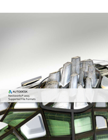
After presssing Create, a progress meter displays on the Statu s bar while processing thee points. The ttimeto processs depends onn the number of points anaalyzed.When proocessing is finished, the section geomettry is created .Transparency contrrol for point cloudsIt can sommetimes be diifficult to see geometry creeated when ssnapping to oor tracing over point cloudssince the points can paartially obscure the geomeetry. To help aaddress this pproblem, poinnt clouds nowwtin the prope rties palette aand from thee Point Cloudsupport trransparency. You can set transparencyRibbon tab when a poiint cloud is seelected.20
es below showw the point cloudcbefore anda after trannsparency hass been applieed.The imageDynamicc UCSPoint clouuds now suppport Dynamic UCS. If an atttached point cloud file includes segmenntation data aasindicated in the Properrties palette, you can begin drawing onn the face of a point cloud without having toU Simply ensure Dynammic UCS is turnned on and alll point cloud object snapss aremanually change the UCS.turned offf. Then pass thet cursor over a face of thhe point clou d to begin drrawing.Point clooud object snnapsThe 3D Obbject Snap tabb in the Draftinng Settings diaalog box has bbeen rearrangeed to make rooom for additionalpoint cloud object snapp modes, including Intersecttion, Edge, Corner, Perpenddicular to Edgee, and Centerline.21
nes ofThe Interssection point cloud object snap enabless you to snapp to the apparrent intersecttion of two lina sectioneed point cloudd.The Edge object snap snapssto the edgeeof two inntersecting pplanes and thee Corner objeect snap snapps toer of three intersecting planes.the corneThe Perpeendicular to EdgeEobject snnap enables youy to draw pperpendicularr to the edge of twointersecting planes.erline object snapsenables you to snap tot the centerrline of a cylinndrical shape.The Cente22
oud crop staatesPoint cloThe Croppping panel onn the Point Clooud Ribbon taab includes n ew tools thatt enable you tto save andrestore naamed croppinng states. Thee cropping staates maintainn the croppingg boundary of the point clooudas well as the visibility of the scans and regions asa they’re dis played in thee point cloud manager. Youu canew POINTCLOOUDCROPSTAATE commandd to list and d elete crop staates.use the nePoint Clooud ManageerThe Point Cloud Managger now alwaays displays thhe on/off butttons for scanns and regionss. Names ared if necessary to display thee button, sincce a tooltip a lways displayys the full namme when thetruncatedcursor is movedmover ana item.23
Renderr engineA new renndering enginne in AutoCADD 2016 replacces the previoous renderingg engine. Thiss physically baasedpath tracing renderer providespa simmpler way to render in AuttoCAD that caan produce bbetter results. Thenew render UI has signnificantly fewer settings coompared withh the previouss render UI. MMany of theprevious settingssweree removed as they are no longer valid wwith the new rendering engine.The Render Ribbon panel on the Vissualize Ribbon tab is upda ted to support the new reendering engine. Itincludes a size drop-doown list where you can quickly select frrom standard predefined rrender sizes oorchoose MoreMOutput SettingsSto acccess the new Render to Ouutput Settinggs dialog box.In the Rennder to Size Ouutput Settingss dialog box, you can specifyy the image size and resoluttion. And you canchoose to automaticallyy save the rendered image tot a file, includding BMP, TGA, TIF, JPEG, aand PNG formmats.The Render Presets listt on the Visuaalize Ribbon tabt includes aadditional opttions, enablinng you to controlthe rendeer quality by settingseither the number of levels to reender or howw much time tto render. Toooltipsassist youu in making ann appropriatee choice.24
RPreseets Manager iss much simpler than the pprevious Rendder Presets MManager. You canThe new Rendercreate, modify, and deelete custom renderrpresetts. Specify rennder preset nname and desscription as wwell asthe duration and accurracy. You can render direcctly from the RRender Preseets Manager, choosing towthe currentcviewpport, or a speccified region in the current viewport. WWhenrender in the Render window,er window, a drop-downdlisst enables yo u to specify tthe render sizze in addition torenderingg in the rendeselecting one of the prreset render qualityqoptionns.posure palettte offers pow erful new imaage-based ligghting (IBL)A new Render Environment and Expn access it froom the Rendeer panel of thee Visualize Ribbon tab.environments. You cane Environmennt control is tuurned on, youu can select frrom predefined IBL enviroonments.When the25
nvironments automaticallyy apply lightinng effects. Soome of them iinclude 360-ddegreeThe IBL enbackgrounnd images thaat emulate a realistic environment as yyou orbit arouund the modeel. The viewportmust be inn a perspectivve view and youy must rendder to see thee IBL environment.A control in the Render Environmennt and Exposuure palette ennables you too use a customm backgrounddustom imagess are static annd do not emuulate a realisttic 3D environnment as youu rotate.image. CuAdditionaal controls in thet Render Ennvironment anda Exposure palette enabble you to adjust the Expossureand Whitee Balance.The Expossure slides beetween Brightt and Dark.26
e Balance sliddes between CoolCand Warrm.The WhiteThe new renderrwindoow displays thhe current rennder process and enables you to save a snapshot, zooomin and outt while rendeering, and prinnt the rendered image. Reender history is displayed in the expanddedsection off the render window.w27
Coordinnation moodelAutoCAD 2016 has addded support forf attaching coordinationcmodels to a drawing. A cooordination mmodelus trades throough the pre--constructionn and construcctionis a model used for virttual coordinaation of variouphases off a project. Cooordination modelsmare not displayed inn the 2D Wireeframe visual style.Navisworks supporttAutoCAD 2016 supportts attaching Autodesk ANaavisworks fil es, in either tthe NWD or NNWC file formmat.nce files, incluuding the AttaachYou can attach them using the same tools you use to attach oother referentool and thet External ReferencesRManager.MNavisworks files are lissted among thhe other suppported file typpes.ew CMATTACCH command (-CMATTACHH for the commandYou can also attach Naavisworks filess using the neon).line versio28
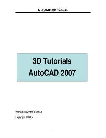
ool you use too attach a Navvisworks file, the Attach Cooordination MModel dialog boxRegardlesss of which tois displayeed. In here yoou can specifyy typical controls includingg Path type, Innsertion poinnt, Scale, andRotation, as well as Dissplay options that are speccific to Naviswworks files. Iff your drawingg is part of thheou can hide that part of thhe model wheen it is attached. Just makee sure Showcoordinattion model, yocurrent drrawing geometry in model is not checked. That wayy your drawingg geometry iss not duplicatted inthe modeel. You can alsso automaticaally zoom to thet coordinattion model wiithin the drawwing.Controls ono the Coordiination Modeel contextual Ribbon tab mmake it easy too differentiatte between thhedrawing geometrygandd attached cooordination models. Color FFading controols the amounnt of blackblended ono all attached coordinatioon models. Oppacity Fadingg controls the amount of dimming throuughtranspareency for all atttached coordination modeels.Color and opacity fadinng are set to 0 in the image on the left (below), makking it difficultt to differentiatethe drawing geometry from the attaached coordination mode l. In the imagge on the righht, both controlserentiate the drawing fromm the model.are set to 50, making itt easy to diffeordination moodel is not suppported on 322-bit systemss. To attach cooordinationNOTE: Atttaching a coomodels, youy need a 644-bit system, anda hardwaree accelerationn must be turrned on.BIM 360 add-in for AutoCADAennhancementsThe BIM 3603 TM add-in is enhanced sos that you caan attach singgle or mergedd models fromm BIM 360 TMGlue software to AutooCAD drawings. The new AttachAtool is accessible frrom the BIM 3360 Ribbon taab.29
or BIM 360 Glue, you can accessayour p rojects directtly from AutooCAD by signinngIf you havve a license fointo your A360 accounnt and selectinng the projectt host. You caan select whicch model or mmerged modeel youwish to atttach and then specify its location withiin the currentt drawing.You can select the attaached model tot access the Coordinationn Model conttextual Ribbon tab where yyoud opacity fadiing.can adjustt its color andIf a model from BIM 3660 Glue is attached to a DWWG TM drawinng and the drawing is saveed, when thedrawing iss re-opened, the latest verrsion of the attached mod el is automattically loaded.30
Installaation andd configurrationImprovved graphiicsThe appeaarance of lineeweights (for continuous liinetypes) andd curves (circlles, arcs, ellippses, and ellippticalarcs) has been enhanced in AutoCAAD 2016. To seee these imprrovements, yyour graphics hardware muustX 11-capablee and you muust have hardware acceler ation turned on. A new coontrol in thebe DirectXGraphics Performance dialog box ennables you too take advant age of improved graphics for capabledevices. YouY can accesss Graphic Perrformance froom the Statuss bar icon.When enaabled, you can display perffect curves inn the 2D wirefframe visual sstyle and they will be smooothat any zooom level.Two new variables offeer additional control over the display wwhen high-quaality geometrry is enabled. TurnNG on
in AutoCAD s three meth tion to select mand is run. variable. Help window on. In AutoCA on menu. rrently visibl 2016 to prov ods of creatio an object. T You can set , an animated D 2016 this e, the UI Find ide more fle n: rectangul he last used c your own de d arrow point functionality er w