Transcription
HANDBOOKTECHNICAL IRRIGATION INFORMATIONTHETHEHANDBOOKOFOFTECHNICALA C oIRRIGATIONm p l e t e R e f e rINFORMATIONence Source for the ProfessionalA Complete Reference Source for the ProfessionalRESIDENTIAL & COMMERCIAL IRRIGATIONBuilt on Innovation hunterindustries.com
PREFACEHunter’s Handbook of Technical Irrigation Information is areference guide for all professionals whose livelihood takes theminto the realm of irrigation. Contractors, architects, designers andengineers alike are now able to benefit from the wide spectrumof information that has been gathered from numerous sourcesinto a single document.For additional information on irrigation, visit our website athunterindustries.com
GENERAL2 SlopeHYDRAULICS4 Dynamic Pressure Determination5 Friction Factor Pipe Sizing8 Friction Loss in Pipe8 Static Pressure Determination9 Velocity Head9 Velocity of Flow10 Water HammerINDUSTRY MANDATES11 AB 1881, California Calculation of Maximum Applied Water Allowance (MAWA)12 AB 1881, California Calculation of Estimated Total Water Use (ETWU)14 Maximum System Capacity RequirementPUMPS16 Break Horsepower16 Horsepower Required in Pumping Water17 Net Positive Head Available18 Total Dynamic Head19 Water Horsepower RequirementsSCHEDULING20 Coefficient of Uniformity21 Distribution Uniformity22 Precipitation Rate24 How to Calculate Areas25 Scheduling Coefficient25 Irrigation Frequency26 Sprinkler Run TimeHUNTER Handbook of Technical InformationFORMULASFORMULAS
GENERALSLOPESlope, as used in irrigation, is a measure of the incline of an area. It can be described as (1) a percent, formula “A”,(2) a degree, formulas “B” and “C”, or (3) a ratio, formula “D”. The greater the incline, the greater the tendencyfor runoff.A. The percent of slope can bedetermined by dividing the netchange in elevation between twopoints (Rise) by the horizontaldistance between those twopoints (Run).B. The degree of slope describesa slope as the angle of the slope(at “A”) from the horizontal plane.This method is useful when takingfield measurements as “c” represents the measured distanceup a slope and “a” equals theelevation change.RiseS RunPoint Basin A cPoint BRisePoint AcaRunPoint AWhere:S the percent of slopeRise the net elevation changein elevation betweentwo pointsHorizontal PlaneWhere:A the angleRun the horizontal distancebetween the two pointsa the height of the righttriangleNote: The units for Rise and Runcan be any unit of linear measure,but they must be the same for boththe Rise and Run.c the length of the hypotenuse of a right triangleExample:What is the slope for a bank 40 ft.wide (run) on which the elevation atthe top (point “B”) is 20 ft. higherthan the toe of the slope (point “A”)20S 40S 0.50 or 50%HUNTER Handbook of Technical InformationExample:a 20 feetc 44.72 feet20sin A 44.72sin A 0.4472A 26 34'FORMULAS GENERAL2
SLOPE (continued)C. The degree of slope describesa slope as the angle of the slope(at “A”) from the horizontal plane.This method is useful when determining the slope from plot plans thatinclude elevation. In thisdiagram “b” represents thehorizontal distance between points“A” and “B” and “a” equals theelevation change between points “A”and “B.”atan A bPoint BD. Describing a slope as a ratio suchas 2:1, 1:1 or 4:1, indicates the numberof feet of runfor every one foot ofrise. For instance a 2:1 slope indicatesthere would be two feet ofhorizontaldistance for every one foot changeof elevation. A 1:1 would change onefoot of elevation for every one foot ofhorizontal run.This can be calculated by dividing theamount of elevation change by thehorizontal distance over which thischange occurred.RiseSr Run : 1Point BaPoint ARisePoint AbHorizontal PlaneRunWhere:Sr the slope ratioWhere:A the angleRise the net elevation changebetween two pointsa the height of the right triangleb the horizontal distanceRun the horizontal distancebetween the two pointsExample:a 20.0 feetb 40.0 feetNote: the units for Rise and Runcan be any unit of linear measure, butthey must be the same for both theRise and Run.20.0tan A 40.0Example:A slope on a project is 20 feet high(rise) over a distance of 40 feet (run).What is the slope ratio?tan A 0.4472A 26 34'40Sr 20 : 1Sr 2 : 1Note: See page 46 and page 47for more information on slopes.HUNTER Handbook of Technical InformationFORMULAS GENERAL3
HYDRAULICSDYNAMIC PRESSURE DETERMINATIONDynamic pressure is the pressure when water is flowing in the system. Dynamic pressure in a system can bedetermined by flow tests, using pressure gauges or by calculation if information on pipe types and sizes, valves,meters or other appurtenances are known. The dynamic pressure can be calculated at a given point in the systemby starting with a known dynamic pressure at some point, adjusting for elevation change and subtracting frictionlosses in pipe, fittings, valves, meters, etc. as shown below:Dynamic Pressure PSI dynamic ! h e elevationh - h f pipe - h f fittings - h f valvesWhere:PSIdynamic the known dynamic pressure at a given point in PSIhe elevation pressure change due to elevation in PSIhf pipe the PSI loss due to friction losses in the pipehf fittings the PSI loss due to friction losses in fittingshf valves the PSI loss due to friction losses in valves, meters or other appurtenances between the sourceand the given point in the systemControl Valve PointB100 ft. Point AELEVATION VIEWWater MeterExample:In the diagram above the dynamic pressure at point “A” is 90 PSI. The pipe is 2 inch class 315 PVC, 200 ft. frompoint “A” to point “B” with a flow rate of 40 GPM. According to the manufacturer, the control valve will lose 1.0 PSIat 40 GPM.90.00PSI at point “A”- 43.30PSI loss due to elevation gain (100 ft x 0.433 PSI per feet)46.70PSI at point “B”2.82PSI friction loss in pipe (1.41 PSI loss per 100 feet x 200 feet / 100)43.88Subtotal0.28PSI friction loss in fittings (estimate, 10% of friction loss in pipe)43.60Subtotal1.00PSI loss in valve (from manufacturer data)42.60PSI dynamic pressure at point “B”HUNTER Handbook of Technical InformationFORMULAS HYDRAULICS4
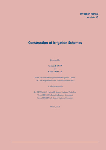
FRICTION FACTOR PIPE SIZINGThis Friction Factor is used to determine the maximumflow in gallons per minute through any section of lateralline pipe while not exceeding a predetermined pressureloss (pressure variation). In order to minimize unevendistribution, sprinklers should operate with pressurevariation between sprinklers of not more than 10 to 20% of the desired sprinkler operating pressure.P #PFf 0 L vcWhere:Ff Friction Factor, the allowable pressure lossper 100 feet of pipe, in psiPo Sprinkler operating pressure in PSIP v Pressure Variation allowed between thevalve and the last sprinkler on the circuitbeing sized, usually 10% or 20% of thedesired sprinkler operating pressureLc Critical Length of pipe from control valveto farthest head in hundreds of feetExample:A) You must determine the amount of pressurevariation you can allow between the valve and thelast sprinkler head. This is usually 10% to 20% of theoperating pressure of the sprinklers on that particularsection. For this example we will use 10% (0.10)variation.If a control valve operates a group of sprinklers whichrequire 30 PSI to operate (operating pressure Po) the10% pressure variation (pressure variation P v) wouldallow a total variation of 3.0 PSI from the valve to thefarthest head. (0.10 x 30 PSI 3.0 PSI)B) Determine the Critical Length (Lc)Next you must determine the distance the water travelsfrom the control valve to the farthest head. That is notnecessarily the total length of pipe in the section butjust the length of the pipe through which the waterflows from the valve to the farthest head. Divide thisnumber by 100 to determine the hundreds of feet fromthe valve to the farthest head.This is called the Critical Length and represents thehundreds of feet of pipe in which you can afford to losethe pressure you determined was acceptable forpressure variation in step “A”. Control Valve for these sprinklers Sprinkler head requiring 30 PSI and delivering2.0 GPM at that pressure20 ft.40 ft.80 ft.40 ft.60 ft.Figure 1In this diagram you must decide the path the water flows from the valve to the farthest head and calculatethat distance in feet. The water flow path is shown in Fig. 2 and is represented by the pipe with the check pattern.Notice the distance of the branch line is NOT included in the distance. This is because the water flowing to thefarthest head does not travel down that length of pipe and therefore any pressure loss occurring in the branchdoes not affect the pressure in the Critical Length.HUNTER Handbook of Technical InformationFORMULAS HYDRAULICS5
FRICTION FACTOR PIPE SIZING (continued) Farthest head20 ft.180 ft.Figure 2In Fig. 2 the water traveling from the valve to the farthest head must pass through 200 feet of pipe. This dividedby 100 gives a Critical Length (Lc) in hundreds of feet, of 2.0.C) Determine the rate at which you can lose pressurein the pipe. This is called the Friction Factor (Ff) which isthe allowable PSI loss per one hundred feet of pipe. Wecan determine this allowable rate of loss by dividing theallowable pressure loss (in PSI) by the critical length (inhundreds of feet) by using the formula below.The sprinklers mentioned in (Fig. 1) require 30 PSI tooperate and a distance from the valve to the farthesthead of 200 feet. Using the formula below we can determine the Friction Factor.Ff Po # PvL c /100lFf 30 # 0.10200/1003Ff 2Ff 1.5 allowable PSI loss per 100 ft of pipeHUNTER Handbook of Technical InformationThe Friction Factor indicates that the pipe is to be sizedso that no section of pipe exceeds a pressure loss of1.5 PSI per 100 ft. This ensures that over the 200 feetfrom the valve to the farthest head, the total PSI losswill not exceed the 3.0 PSI allowable loss (10% of thesprinkler operating pressure). The Friction Factor canbe used like a budget. It gives us a guideline by whichwe can size the pipe without having excessive pressureloss in any section.For the lateral pipes (those downstream of the controlvalve) use Class 315 PVC for Z\x inch pipe and Class 200PVC for all larger sizes. Although this requirement forClass 315 and Class 200 is not mandatory and may varyon many larger installations, it is typical for landscapeprojects from residential through medium commercialprojects in the South and Western United States.At this point turn to the Friction Factor Shortcut chartsin the Tables section, page 52. Find the Chart for theFriction Factor closest to the one calculated for yoursprinkler system section. (In this case there is a chartfor a Friction Factor of 1.5 PSI allowable loss per100 ft. When there is no chart for the exact FrictionFactor calculated, round off the Friction Factor tothe nearest chart value.)FORMULAS HYDRAULICS6
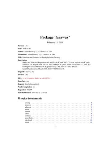
FRICTION FACTOR PIPE SIZING (continued)Figure 3 represents a portion of the Friction Factor Shortcut chart from page 52. The chart in the appendixshould look like Fig. 3 shown below.Friction FactorThe “Max. GPM” listed in the chart represent the maximum GPM that each pipe type/size can sustain withoutexceeding a 1.5 PSI loss per 100 feet.1.50 Max. GPM½" CL 315 PVC2.8¾" CL 200 PVC5.71" CL 200 PVC10.81¼" CL 200 PVC19.91½" CL 200 PVC28.52" CL 200 PVC51.12½" CL 200 PVC84.33" CL 200 PVC141.4Using the maximum flow rates in the chart as guides,the lateral line pipes can be sized with the assurancethe total PSI loss from the control valve to the farthestsprinkler will not exceed 10% of the sprinkler operatingpressure (3.0 PSI).First determine the quantity of water in GPM passingthrough each section of pipe. A section may need to besized differently if there is any change in the GPM so it isimportant to determine the flows carefully. Figure 4 liststhe GPM flowing through each section of pipe. Noticethe section labeled “10” GPM. The 10 GPM is the flow toall sprinkler heads beyond that point and includes boththe straight run and the branch line.Figure 314121064242Figure 4Using the chart (Fig. 3) as a guide, sizes can be assigned to each pipe section.1¼"1¼"1"1"¾"½"¾"½"Figure 5Note that in the section with 6 GPM we used 1" pipe. The chart allows up to 5.7 GPM in ¾" pipe and some designersmay choose to use ¾" instead of 1". It is acceptable to use ¾” pipe even though it exceeds the allowable loss (theFriction Factor), because pressure is conserved in some sections where the flow is below the maximum allowed.HUNTER Handbook of Technical InformationFORMULAS HYDRAULICS7
FRICTION LOSS IN PIPESTATIC PRESSURE DETERMINATIONThe Hazen-Williams equation can be expressedas follows and is the most commonly used formulafor calculating pressure loss in PVC pipe.Static pressure is the measure of pressure when the wateris at rest. This pressure is determined by the weight of acolumn of water resting on one square inch and expressedas the pounds per square inch (PSI). The weight of a columnof water one foot high will create 0.433 pounds of pressureover every square inch. Static pressure can be determinedas follows:1.852100 1.852 Qh f 0.00090914 a C k4.866 LdWhere:hf Head loss due to friction in poundsper square inch (PSI)C Hazen Williams coefficient for roughnessof the inside of the pipeQ Flow in gallons per minute (GPM)d Inside diameter of pipe in inchesL Length of pipe in feetExample:A 2-inch class 200 PVC pipe (I.D. 2.129") 500 feetin length will deliver 50 GPM to an irrigation system.Compute the friction loss in the pipeline.100 1.852 50 1.852 lh f 0.00090194 a 150 k b5002.129 500h f 7.544 PSIPs A ! 0.433 HWhere:Ps Static pressure at a given point in the system,in pounds per square inch (PSI)A Static pressure at starting point in PSI0.433 A constant representing the weight of water ina column one foot high as expressed in poundsper square inchH The net vertical change in elevation from thesurface of the water to the given point in thesystem in feet, increase in elevation, uphill,results in PSI loss (–0.433) downhill results PSIgain ( 0.433)Control Valve40 ft(12 m)Water MeterELEVATION VIEW Point A60 PSI (414 kPa)(Static pressure)HUNTER Handbook of Technical InformationFORMULAS HYDRAULICS8
STATIC PRESSUREDETERMINATION (continued)Example:Determine the static pressure at the entrance tothe control valve if the static pressure at the meteris 60 PSI. (Note: If change in elevation is downhill,the elevation change (H) would be a positive.)Ps 60 - 0.433 # 40hPs 42.68 PSIVELOCITY HEADThe velocity head is the pressure required tomove the water through the system.H v V 2 /2gWhere:Hv velocity head, the energy required to movethe water at the intended velocity, in feetV water velocity, in feet per secondFor static pressure in metric units, use:Ps A - 9.79 HPs 414 - 9.79 # 12hPs 296.52 kPaWhere:Ps Static pressure at a given point in thesystem, in kiloPascals (kPa)A acceleration due to gravity (32.2)Example:What is the Velocity Head required to move40 GPM through a 2 inch Class 315 PVC pipe?H v 4.15h /64.4H v 0.27 feet2 Static pressure at starting point in kPa9.79 A constant representing the weight ofwater in a column one meter high asexpressed in kPaHg the net vertical change in elevation fromthe surface of the water to the givenpoint in the system in metersVELOCITY OF FLOWThe velocity of flow is a calculation of the speed ofwater moving in a closed pipe system.V 0.408Qd2Where:V flow velocity in feet per second (fps)Q flow in gallons per minute (GPM)d inside diameter of pipe in inches0.408 constant used to convert units into feetper secondExample: What is the velocity of flow for a 1 inch class 200 PVCpipe (1.169 inch I.D.) with a flow rate of 10 GPM?V 0.408 c10 m 1.169h2V 2.99 fpsHUNTER Handbook of Technical InformationFORMULAS HYDRAULICS9
WATER HAMMERThis formula is used to estimate the total surge pressure developed when there is a sudden reduction or cessationin the velocity of flow. This is typical when a control valve closes.Pt Po aV # L # 0.07 ktWhere:P t the total pressure developed, in PSIPo the operating pressure at the time of valveclosing, in PSIV velocity at the time the reduction in velocityoccurred, in feet per secondL Length of straight pipe between source andpoint where reduction in velocity occurred, thiswould be the longest section, in feet (straightpipe means no tee or ell fittings)t seconds during which the velocity was reduced,for example, a valve that closes in a half secondwould have a value for “t” of 0.5Example:An electric remote control valve has a hydraulic closuretime of 0.8 seconds. The main line leading to the valveis 450 feet long with a velocity of 4.2 fps. The system isoperating at 65 PSI at the time of valve closure. What isthe total surge pressure?Pt 65 a4.2 # 450 # 0.07 k0. 8132.3Pt 65 0.8Pt 230.38 PSI0.07 constant used to convert velocity, length andtime into pressureHUNTER Handbook of Technical InformationFORMULAS HYDRAULICS10
INDUSTRY MANDATESAB 1881, CALIFORNIA CALCULATION OF MAXIMUM APPLIEDWATER ALLOWANCE (MAWA)The Maximum Applied Water Allowance (MAWA) is used to determine the amount of water a project will beallowed to use for landscape purposes. This amount determines the limit for projected water use. Projects must bedesigned with an Estimated Total Water Use (ETWU) less than the limit allowed in the MAWA calculation. The useof this formula is mandated by California State Assembly Bill 1881.MAWA EToh 0.62h6 0.7 # LA h 0.3 # SLA h@Where:MAWA Maximum Applied Water Allowance(gallons per year)0.62 Conversion Factor (to gallons)0.7 ET Adjustment Factor (ETAF)EtoLA Landscape Area including SLA (square feet)0.3 Additional Water Allowance for SLASLA Special Landscape Area (square feet) Reference Evapotranspiration(inches per year)Example:(1) A hypothetical landscape project in Fresno, CA, with an irrigated landscape area of 50,000 square feet withoutany Special Landscape Area (SLA 0, no edible plants, recreational areas, or use of recycled water). To calculateMAWA, the annual reference evapotranspiration value for Fresno is 51.1 inches.MAWA 51.1in h 0 .62h6 0.7 # 50, 000ft 2h 0.3 # 0h@ 1, 108, 870 gallons per yearTo convert from gallons per year to hundred-cubic-feet per year:1, 108, 870 1, 482 hundred cubic- feet per year748(100 cubic- feet 784 gallons) (2) In this next hypothetical example, the landscape project in Fresno, CA, has the same ETo value of 51.1 inches anda total landscape area of 50,000 square feet. Within the 50,000 square foot project, there is now a 2,000 squarefoot area planted with edible plants. This 2,000 square foot area is considered to be a Special Landscape Area.MAWA (51.1 in) 0.62 h6 0.7 # 50, 000ft 2h 0.3 # 2, 000ft 2h@ 31.68 # 635, 000 600@ gallons per year 31.68 # 35, 600 gallons per year 1, 127, 808 gallons per year or 1, 508 hundred cubic- feet per yearFor complete information about the California Model Water Efficient Landscape Ordinance, visit the CaliforniaDepartment of Water Resources website scapeordinance/technical.cfmHUNTER Handbook of Technical InformationFORMULAS INDUSTRY MANDATES11
AB 1881, CALIFORNIA CALCULATION OF ESTIMATEDTOTAL WATER USE (ETWU)This formula is used to calculate the estimatedamount of water used in a landscape. The ETWUmust be less than the Maximum Applied WaterAllowance (MAWA), as shown in the previous formula,in order to receive project approval. The use of thisformula is mandated by California State AssemblyBill 1881.Where:ETWU Estimated Total Water Use per year (gallons)PF # HA # SLA kETWU EToh 0.62haSLA Special Landscape Area (square feet)IEEto Reference Evapotranspiration (inches)PF Plant Factor from WUCOLS (see Section 491)HA Hydrozone Area [high, medium, and lowwater use areas] (square feet)0.62 Conversion FactorIE Irrigation Efficiency (minimum 0.71)Example:Using example 1 from page 11, determine the ETWU of an irrigated landscape area of 50,000 square feet without any Special Landscape Areas (SLA 0, no edible plants, recreational areas, or use of recycled water). The ETovalue is 51.1 inches annually, and the plant water use type, plant factor, and hydrozone area are shown in the tablebelow.HydrozonePlant Water UseType(s)1High2Plant Factor (PF)*Hydrozone Area(HA) (square feet)PF x HA(square 0*Plant Factor from WUCOLSETWU 51.1h 0.62hb24, 700 0 l0.71 1, 102, 176 gallons per yearCompare ETWU with MAWA: For this example MAWA (51.1) (0.62) [(0.7 x 50,000) (0.3 x 0)] 1,108,870 gallonsper year. The ETWU (1,102,176 gallons per year) is less than MAWA (1,108,870 gallons per year). In this example,the water budget complies with the MAWA.HUNTER Handbook of Technical InformationFORMULAS INDUSTRY MANDATES12
AB 1881, CALIFORNIA CALCULATION OF ESTIMATEDTOTAL WATER USE (ETWU) (continued)Using example 2 from page 11, determine the ETWU of an irrigated landscape area of 50,000 square feet with2,000 square feet of edible plants (Special Landscape Area). The ETo value is 51.1 inches annually, and the plantwater use type, plant factor, and hydrozone area are shown in the table below.Plant Factor (PF)*Hydrozone Area(HA) (square feet)PF x HA(square 3,5002,0002,000HydrozonePlant Water UseType(s)16SLA1.0*Plant Factor from WUCOLS23, 500ETWU 51.1h 0.62hb 0.71 2, 000 l 31.68h 33, 099 2, 000h 1, 111, 993 gallons per yearCompare ETWU with MAWA. For this example:MAWA 51.1h 0.62h6 0.7 # 50, 000h 0.3 # 2, 000h@ 31.68 # 635, 000 600@ 31.68 35, 600 1, 127, 808 gallons per yearThe ETWU (1,111,993 gallons per year) is less than MAWA (1,127,808 gallons per year). For this example, the waterbudget complies with the MAWA.For complete information about the California Model Water Efficient Landscape Ordinance, visit the CaliforniaDepartment of Water Resources website scapeordinance/technical.cfmHUNTER Handbook of Technical InformationFORMULAS INDUSTRY MANDATES13
MAXIMUM SYSTEM CAPACITY REQUIREMENTThe following formula is to be used to determine the gallons per minute (GPM) necessary for peak water demandperiods. While an area might survive for short periods with less water by utilizing soil moisture reserves, extendedperiods of drought would require the maximum system capacity. The formulas below are a guide—the answer isno better than the factors that go into the formula (e.g. Reference Evapotranspiration Rate, Area, DistributionUniformity, etc.).GPM per hydrozone(s): This formula is used to determine the maximum water required, in GPM, from thesource based on the hydrozone’s characteristics.GPM 0.0104 # Et o # Area # K cDU # Hrs. AvailableTotal Area for Given GPM: This formula may be usedto determine the area that can be irrigated if you knowthe gallons per minute of the water supply.Area GPM # DU # Hrs. Available0.0104 # Et o # K cVariable Value Ranges:GPM gallons per minute requiredWhere:Area area to be irrigated in square feetEtoGPM gallons per minute available from thewater supply peak daily evapotranspiration for the worstcase scenario in inchesArea area to be irrigated in square feetDUKc Crop Coefficient (use 1.0 if actual cropcoefficient is not known)Hrs. Available hours available for irrigation on theworst case dayDU distribution uniformity or irrigation efficiencyEtoHrs. Available hours available for irrigation each dayin the worst case peak daily evapotranspiration for the worstcase scenarioKc Crop Coefficient (use 1.0 if actual cropcoefficient is not known)0.0104 constant for conversion of area, flow andinches per day, etc. into common unitsExample:A park has been designed with 450,000 square feet ofturf, and all areas must be irrigated between 10 p.m.and 6 a.m. The crop coefficient is 60% (0.6) with an average peak evapotranspiration rate of 0.35 inches per day.The system distribution uniformity has been estimatedto be 65%. What will be the maximum GPM required forthe park?GPM 0.0104 # 0.35 # 450, 000 # 0.600.65 # 8GPM 189 Distribution Uniformity or Irrigation Efficiency0.0104 c onstant for conversion of area, flow andinches per day etc. into common unitsExample:A developer has a well on the site of a proposed golfcourse. The well will produce 350 GPM. The course willbe designed with a distribution uniformity of 75%, anda watering window of 12 hours. The peak evapotranspiration rate in the area is 0.30 inches per day and theturf has a crop coefficient of 80% (0.80). How large anarea can be watered with the existing well?350 # 0.75 # 12Area 0.0104 # 0.30 # 0.80Area 1, 262, 019 ft 2 (approx. 29 acres)HUNTER Handbook of Technical InformationFORMULAS MAXIMUM SYSTEM CAPACITY REQUIREMENT14
MAXIMUM SYSTEM CAPACITY REQUIREMENT (continued)Total Area for Given Gallons Per Day: This formula may be used to determine the area that can be irrigatedif you know the gallons available per day. This is the case in some water rationing systems or where a well capacityis the limiting factor.DU # GallonsArea 0.62333 # Et # KocWhere:Area area to be irrigated in square feetDU Distribution Uniformity or Irrigation EfficiencyGallons gallons available from the water supply on the worst case dayEto evapotranspiration for the worst case scenarioKc Crop Coefficient – use 1.0 if actual crop coefficient is not known0.62333 constant for conversion of area, flow and inches per day, etc. into common unitsExample:The city has developed guidelines that allot a commercial project 36,000 gallons of water per day during anextended drought. The area being watered has a distribution uniformity of 60%, an average evapotranspirationrate of 0.22 inches per day and an average crop coefficient of 70% (0.70). How much of their project can besustained with the city’s water allotment?0.60 # 36, 000Area 0.62333 # 0.22 # 0.70Area 225, 017 ft 2 (approx. 5.2 acres)HUNTER Handbook of Technical InformationFORMULAS MAXIMUM SYSTEM CAPACITY REQUIREMENT15
PUMPSBREAK HORSEPOWERThis formula determines the amount of power required at the pump shaft based on the pump efficiency. It does nottake into account any losses in the engine or electric motor.Q#hBHP 3960 # EfWhere:BHP brake horsepower (1 HP 550 ft-lbs/sec)Q pump discharge in gallons per minute (GPM)h total dynamic head in feet3960 constant for conversion of units to brakehorsepowerEf pump efficiency (decimal)Example:A pump with an efficiency of 85% is pumping 500 GPMwith a total dynamic head of 230 feet. What is the brakehorsepower required to drive the pump?500 # 230BHP 3960 # 0.85BHP 34.17HORSEPOWER REQUIRED IN PUMPING WATERThis formula is used to determine the brake horsepower requirements.ft # GPMBHP 3960 # EfWhere:BHP Brake Horsepowerft the number of feet the water is liftedfrom the surface of the water sourceto the discharge pointGPM the gallons per minute being pumped3960 constant for conversion to horsepowerEf pump efficiency (decimal)Example:A pump system is needed to pump 500 GPM from ariver 70 feet up to a golf course water reservoir. What isthe minimum horsepower required to pump this water?This pump is rated at 75% efficient.70 # 500HP 3960 # 0.75HP 11.78 . 12Brake horsepower is the power required at the pumpshaft required to drive the pump.HUNTER Handbook of Technical InformationFORMULAS PUMPS16
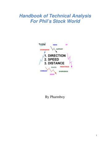
NET POSITIVE HEAD AVAILABLEThe Net Positive Suction Head available is the absolute pressure available at the pump impeller. The Net PositiveSuction Head Available (NPSHA) must exceed the Net Positive Suction Head Requirement (NPSHR) or cavitationwill cause damage to the pump impeller. The NPSHR is determined by the pump manufacturer and is dependentupon pump design and operating conditions.NPSHA H o - H vh - H s - H fExample:Use the diagram and the chart to determine the Net Positive SuctionHead Available. The pump is located 3,000 feet above sea level, the watertemperature is 60 F. The intake line is 20 feet long and the flow rateis 100 GPM. The pressure loss through the foot valve is 1.5 PSI and thepressure loss through the fittings is estimated at 0.5 PSI.Where:Ho atmospheric pressure in feetof waterHv saturation vapor pressure infeet of waterHs vertical height of the impellereye above the water surfacein feetNPSHA 30 - 6 - 1.5 # 2.31h - 0.33 # 0.2 # 2.31h - 0.5 # 2.31hNPSHA 19.21 feet of headhf pressure loss due to frictionin the suction (intake) line infeet of head (pressure lossesin PSI must be multiplied by2.31 to convert to feet)The Net Positive Suction Head Available (NPSHA) can be calculated bythe formula above while the Net Positive Suction Head Required (NPSHR)varies from one pump model to another and can be found with the pumpperformance curves provided by the manufacturer. For any given pumpingsituation and pump model, the NPSHA must exceed the pump’s NPSHR inorder for the pump to operate properly and avoid cavitation.(HO–HV) FOR A RANGE OF TEMPERATURES ANDELEVATIONSWaterTemp. FElevation Above Sea Level (ft)010002000300040005000600040 33.732.531.430.329.228.127.050 33.632.431.330.229.128.026.960 33.432.231.130.028.927.826.770 33.232.030.929.828.727.626.580 32.831.631.529.428.327.226.190 32.431.230.129.027.926.825.7100 31.830.629.528.427.326.225.1110 31.129.928.827.726.625.524.4120 30.128.927.826.725.624.523.4130 28.927.726.625.524.523.322.2140 27.326.125.023.922.821.720.6150 25.424.223.122.020.919.818.7HUNTER Handbook of Technical Information4 inch Class 315 PVC6 feet Min.Water LevelFoot ValveFORMULAS PUMPS17
T
HUNTER Handbook of Technical Information HYDRAULICS DYNAMIC PRESSURE DETERMINATION Dynamic pressure is the pressure when water is flowing in the system. Dynamic pressure in a system can be determined by flow tests, using pressure gauges or by calculation if info