Transcription
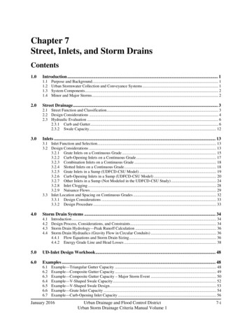
Chapter 7Street, Inlets, and Storm DrainsContents1.0Introduction . 11.11.21.31.42.0Purpose and Background . 1Urban Stormwater Collection and Conveyance Systems . 1System Components . 2Minor and Major Storms . 2Street Drainage . 32.1 Street Function and Classification . 32.2 Design Considerations . 42.3 Hydraulic Evaluation . 62.3.1 Curb and Gutter. 62.3.2 Swale Capacity. 123.0Inlets . 133.1 Inlet Function and Selection . 133.2 Design Considerations . 133.2.1 Grate Inlets on a Continuous Grade . 153.2.2 Curb-Opening Inlets on a Continuous Grade . 173.2.3 Combination Inlets on a Continuous Grade . 183.2.4 Slotted Inlets on a Continuous Grade. 183.2.5 Grate Inlets in a Sump (UDFCD-CSU Model) . 193.2.6 Curb-Opening Inlets in a Sump (UDFCD-CSU Model) . 203.2.7 Other Inlets in a Sump (Not Modeled in the UDFCD-CSU Study) . 243.2.8 Inlet Clogging . 283.2.9 Nuisance Flows . 293.3 Inlet Location and Spacing on Continuous Grades . 323.3.1 Design Considerations . 333.3.2 Design Procedure . 334.0Storm Drain Systems . 344.14.24.34.45.06.0Introduction . 34Design Process, Considerations, and Constraints. 34Storm Drain Hydrology—Peak Runoff Calculation . 36Storm Drain Hydraulics (Gravity Flow in Circular Conduits) . 364.4.1 Flow Equations and Storm Drain Sizing . 364.4.2 Energy Grade Line and Head Losses . 38UD-Inlet Design Workbook . 48Examples . 486.16.26.36.46.56.66.7Example—Triangular Gutter Capacity . 48Example—Composite Gutter Capacity . 49Example—Composite Gutter Capacity – Major Storm Event . 50Example—V-Shaped Swale Capacity . 52Example—V-Shaped Swale Design . 53Example—Grate Inlet Capacity . 54Example—Curb-Opening Inlet Capacity . 56January 2016Urban Drainage and Flood Control DistrictUrban Storm Drainage Criteria Manual Volume 17-i
6.8 Example—Design of a Network of Inlets Using UD-Inlet . 577.0References . 61TablesTable 7-1. Street classification for drainage purposes. 3Table 7-2. Pavement encroachment and inundation standards for the minor storm . 4Table 7-3. Street inundation standards for the major (i.e., 100-year) storm . 5Table 7-4. Allowable street cross-flow . 5Table 7-5. Inlet selection considerations . 13Table 7-6. Splash-over velocity constants for various types of inlet grates . 16Table 7-7. Coefficients for various inlets in sumps. 20Table 7-8. Sump inlet discharge variables and coefficients . 26Table 7-9. Clogging coefficient k for single and multiple units1 . 28Table 7-10. Nuisance flows: sources, problems and avoidance strategies . 31Table 7-11. Bend loss and lateral loss coefficients (FHWA 2009) . 44Table 7-12. Head loss expansion coefficients in non-pressure flow (FHWA 2009) . 45FiguresFigure 7-1. Gutter section with uniform cross slope . 7Figure 7-2. Typical gutter section—composite cross slope . 8Figure 7-3. Calculation of composite street section capacity: major storm . 10Figure 7-4. Reduction factor for gutter flow (Guo 2000b). 11Figure 7-5. Typical v-shaped swale section . 12Figure 7-6. CDOT type r and Denver no. 14 interception capacity in sag . 21Figure 7-7. CDOT type 13 interception capacity in a sump. 23Figure 7-8. Denver no. 16 interception capacity in sump . 24Figure 7-9. Perspective views of grate and curb-opening inlets . 27Figure 7-10. Orifice calculation depths for curb-opening inlets . 27Figure 7-11. A pipe-manhole unit . 40Figure 7-12. Hydraulic and energy grade lines . 40Figure 7-13. Bend loss coefficients . 46Figure 7-14. Manhole benching methods . 47Figure 7-15. Angle of cone for pipe diameter changes . 477-iiUrban Drainage and Flood Control DistrictUrban Storm Drainage Criteria Manual Volume 1January 2016
Chapter 7Streets, Inlets, & Storm Drains1.0Introduction1.1Purpose and BackgroundThe purpose of this chapter is to provide designguidance for stormwater collection andconveyance utilizing streets and storm drains.Procedures and equations are presented for thehydraulic design of street drainage, locatinginlets and determining capture capacity, andsizing storm drains. This chapter also includesdiscussion on placing inlets to minimize thepotential for icing. Examples are provided toillustrate the hydraulic design process and Excelworkbook solutions accompany the handcalculations for most example problems.Photograph 7-1. From 2006 to 2011, hundreds of street andarea inlet physical model tests were conducted at the CSUHydraulics Laboratory, facilitating refinement of the HEC-22methodology for inlets common to Colorado.The design procedures presented in this chapterare based upon fundamental hydrologic andhydraulic design concepts. It is assumed that the reader has an understanding of basic hydrology andhydraulics. A working knowledge of the Rational Method (Runoff chapter) and open channel hydraulics(Open Channels chapter) is particularly helpful. The design equations provided are well accepted andwidely used. They are presented without derivations or detailed explanation but are properly referenced ifthe reader wishes to study their background. Inlet capacity, as presented in this chapter, is based on theFHWA Hydraulic Circular No. 22 (HEC-22) methodology (FHWA 2009), which was subsequentlyrefined through a multi-jurisdictional partnership led by Urban Drainage and Flood Control (UDFCD),where hundreds of physical model tests of inlets commonly used in Colorado were performed at theColorado State University (CSU) Hydraulics Laboratory. The physical model study is further detailed intechnical papers available at www.udfcd.org. Additionally, UDFCD developed an inlet design tool, UDInlet, which incorporates the findings of the physical model. UD-Inlet is also available atwww.udfcd.org.1.2Urban Stormwater Collection and Conveyance SystemsUrban stormwater collection and conveyance systems are critical components of the urban infrastructure.Proper design is essential to minimize flood damage and limit disruptions. The primary function of thesystem is to collect excess stormwater in street gutters, convey it through storm drains and along the streetright-of-way, and discharge it into a detention basin, water quality best management practice (BMP), orthe nearest receiving water body (FHWA 2009).Proper and functional urban stormwater collection and conveyance systems: Promote safe passage of vehicular traffic during minor storm events. Maintain public safety and manage flooding during major storm events. Minimize capital and maintenance costs of the system.January 2016Urban Drainage and Flood Control DistrictUrban Storm Drainage Criteria Manual Volume 17-1
Streets, Inlets, & Storm Drains1.3Chapter 7System ComponentsUrban stormwater collection and conveyancesystems are comprised of three primarycomponents:1. Street gutters and roadside swales,2. Storm drain inlets, and3. Storm drains (with appurtenances likemanholes, junctions, etc.).Street gutters and roadside swales collect runofffrom the street (and adjacent areas) and conveythe runoff to a storm drain inlet whilemaintaining the street’s level of service.Photograph 7-2. The capital costs of storm drain constructionare high, emphasizing the importance of sound design.Inlets collect stormwater from streets and other land surfaces, transition the flow into storm drains, andprovide maintenance access to the storm drain system. Storm drains convey stormwater in excess ofstreet or swale capacity along the right-of-way and discharge into a stormwater management facility ordirectly into a receiving water body. In rare instances, stormwater pump stations (the design of which isnot covered in this manual) are needed to lift and convey stormwater away from low-lying areas wheregravity drainage is not possible. All of these components must be designed properly to achieve theobjectives of the stormwater collection and conveyance system.1.4Minor and Major StormsRainfall events vary greatly in magnitude and frequency of occurrence. Major storms produce large flowrates but rarely occur. Minor storms produce smaller flow rates but occur more frequently. For economicreasons, stormwater collection and conveyance systems are not normally designed to pass the peakdischarge during major storm events without some street flooding.Stormwater collection and conveyance systems are designed to pass the peak discharge of the minorstorm event (and smaller events) with minimal disruption to street traffic. To accomplish this, the spreadand depth of water on the street is limited to some maximum mandated value during the minor stormevent. Inlets must be strategically placed to pick up excess gutter or swale flow once the limitingallowable spread or depth of water is reached. The inlets collect and convey stormwater into stormdrains, which are typically sized to pass the peak flow rate (minus the allowable street flow rate) from theminor storm without any surcharge. The magnitude of the minor storm is established by local ordinancesor criteria, and the 2- or 5-year storms are commonly specified, based on many factors including streetfunction, traffic load, vehicle speed, etc.Local ordinances often also establish the return period for the major storm event, generally the 100-yearstorm (although it may be a lesser event for some retrofit projects with site constraints). During thisevent, runoff exceeds the minor storm allowable spread and depth in the street and capacity of stormdrains, and storm drains may surcharge. Street flooding occurs, and traffic is disrupted as the streetfunctions as an open channel. The designer must evaluate and design for the major event with regard tomaintaining public safety and minimizing flood damages.7-2Urban Drainage and Flood Control DistrictUrban Storm Drainage Criteria Manual Volume 1January 2016
Chapter 7Streets, Inlets, & Storm Drains2.0Street Drainage2.1Street Function and ClassificationAlthough streets play an important role in stormwater collection and conveyance, the primary function ofa street or roadway is to provide for the safe passage of vehicular traffic at a specified level of service. Ifstormwater systems are not designed properly, this primary function will be impaired. To ensure thisdoes not happen, streets are classified for drainage purposes based on their traffic volume, parkingpractices, and other criteria (Wright-McLaughlin Engineers 1969). The four street classifications are: Local: Low-speed traffic for residential or industrial area access. Collector: Low/moderate-speed traffic providing service between local streets and arterials. Arterial: Moderate/high-speed traffic moving through urban areas and accessing freeways. Freeway: High-speed travel, generally over long distances.Table 7-1 provides additional information on the classification of streets for drainage purposes.Table 7-1. Street classification for drainage purposesStreetClassificationFunctionSpeed/Number ofTraffic LanesSignalization atIntersectionsStreet ParkingLocalProvides access toresidential and industrialareasLow speed / 2lanesStop signsOne or bothsides of thestreetCollectorCollects and conveytraffic between local andarterial streetsLow to moderatespeed / 2 to 4lanesStop signs ortraffic signalsOne or bothsides of thestreetArterialDelivers traffic betweenurban centers and fromcollectors to freewaysModerate to highspeed / 4 to 6lanesTraffic rovides rapid andefficient transport overlong distancesHigh-speed / 4 ormore lanesSeparatedinterchanges(limited access)AlwaysprohibitedJanuary 2016Urban Drainage and Flood Control DistrictUrban Storm Drainage Criteria Manual Volume 17-3
Streets, Inlets, & Storm DrainsChapter 7Proper street drainage is essential to: Maintain the street’s level of service. Minimize danger and inconvenience to pedestrians during storm events (FHWA 1984). Reduce potential for vehicular skidding and hydroplaning. Maintain good visibility for drivers (by reducing splash and spray).2.2Design ConsiderationsCertain design considerations must be taken into account in order to meet street drainage objectives. Forthe minor storm, the primary design objective is to keep the spread (encroachment onto the pavement)and depth (inundation) of stormwater on the street below acceptable limits for a given return period offlooding. As mentioned previously, when stormwater collects on the street and flows down the gutter, thespread (width) of the water increases as more stormwater is collected and conveyed down the street andgutter. Left unchecked, the spread of water will eventually hinder traffic flow and become hazardous(e.g., hydroplaning, reduced skid resistance, visibility impairment from splash back, engine stalls). Basedon these considerations, UDFCD has established encroachment and inundation standards for the minorstorm event. These standards were presented in the Policy chapter and are repeated in Table 7-2 forconvenience.Table 7-2. Pavement encroachment and inundation standards for the minor stormStreetClassificationLocalMaximum Encroachment and InundationNo curb overtopping. Flow may spread to crown of street.CollectorNo curb overtopping. Flow spread must leave at least one lane free ofwater.ArterialNo curb overtopping. Flow spread must leave at least one lane free ofwater in each direction, and should not flood more than two lanes ineach direction.FreewayNo encroachment is allowed onto any traffic lanes.During the major event, flood protection and human safety replace drivability as the design criteria withregard to street inundation (depth of flow). UDFCD has established street inundation standards duringthe major storm event. These standards were given in the Policy chapter and are repeated in Table 7-3 forconvenience.7-4Urban Drainage and Flood Control DistrictUrban Storm Drainage Criteria Manual Volume 1January 2016
Chapter 7Streets, Inlets, & Storm DrainsTable 7-3. Street inundation standards for the major (i.e., 100-year) stormStreet ClassificationLocal and CollectorArterial and FreewayMaximum Depth and Inundated AreaResidential dwellings and public, commercial, and industrialbuildings should be no less than 12 inches above the 100-yearflood at the ground line or lowest water entry of the building.The depth of water over the gutter flow line should not exceed12 inches.Residential dwellings and public, commercial, and industrialbuildings should be no less than 12 inches above the 100-yearflood at the ground line or lowest water entry of the building.The depth of water should not exceed the street crown to allowoperation of emergency vehicles. The depth of water over thegutter flow line should not exceed 12 inches.Standards for the major storm and street cross-flows are also required. These standards apply atintersections, sump locations, and for culvert or bridge overtopping scenarios. The major storm needs tobe assessed to determine the potential for flooding and public safety. Street cross-flows also need to beregulated for traffic flow and public safety reasons. These allowable street cross-flow standards weregiven in the Policy chapter and are repeated in Table 7-4 for convenience.Table 7-4. Allowable street cross-flowStreet ClassificationLocalInitial Storm Flow6 inches of depth in cross-pan.CollectorWhere cross-pans allowed,depth of flow should notexceed 6 inches.None.Arterial/FreewayMajor (100-Year) Storm Flow12 inches of depth above gutterflow line.12 inches of depth above gutterflow line.No cross-flow. Maximum depth atupstream gutter on road edge of 12inches.Once the allowable spread (pavement encroachment) and allowable depth (inundation) have beenestablished for the minor storm, the placement of inlets can be determined. The inlets will remove someor all of the excess stormwater and thus reduce the spread and depth of flow. The placement of inlets iscovered in Section 3.0. It should be noted that proper drainage design seeks to maximize the fullallowable capacity of the street gutter in order to minimize the cost of inlets and storm drains.Two additional design considerations are gutter geometry and street slope. Most urban streets incorporatecurb and gutter sections. Various types exist, including spill shapes, catch shapes, curb heads, andmountable, a.k.a. “rollover” or “Hollywood” curbs. The shape is chosen for functional, cost, or aestheticreasons and does not dramatically affect the hydraulic capacity. Swales are used along some semi-urbanstreets, and roadside ditches are common along rural streets. Cross-sectional geometry, longitudinalslopes and swale/ditch roughness values are important in determining hydraulic capacity and are coveredin the next section.January 2016Urban Drainage and Flood Control DistrictUrban Storm Drainage Criteria Manual Volume 17-5
Streets, Inlets, & Storm Drains2.3Hydraulic EvaluationHydraulic computations are performed to determine thecapacity of roadside swales and street gutters and theencroachment of stormwater onto the street. The designdischarge is based on the peak flow rate and usually isdetermined using the rational method (covered in the nexttwo sections and in the Runoff Chapter). Although gutter,swale/ditch and street flows are unsteady and non-uniform,steady, uniform flow is assumed for the short time period ofpeak flow conditions.2.3.1Curb and GutterChapter 7Street Hydraulic CapacityThis term typically refers to thecapacity from the face of the curb tothe crown (for the minor event).Typically, the hydraulic computationsnecessary to determine street capacityand required inlet locations areperformed independently for eachside of the street. Additionally, flowand street geometry frequently differfrom one side of a street to the other.Both the longitudinal and cross (transverse) slope of a street are important in calculating hydrauliccapacity. The capacity of the street increases as the longitudinal slope increases. UDFCD prescribes aminimum longitudinal slope of 0.4% for positive drainage (Wright-McLaughlin 1969). Public safetyconsiderations limit the maximum allowable flow capacity of the gutter on steep slopes. The cross sloperepresents the slope from the street crown to the interface of the street and gutter, measured perpendicularto the direction of traffic. UDFCD recommends a minimum cross slope of 1% for positive drainage;however, a cross slope of 2% is more typical. Driver comfort and safety considerations limit themaximum cross slope. Use of standard curb and gutter sections typically produces a composite sectionwith milder cross slopes for drive lanes and steeper cross slopes within the gutter width for increased flowcapacity.Each side of the street is evaluated independently. The hydraulic evaluation of street capacity includesthe following steps:1. Calculate the street capacity based upon the allowable spread for the minor storm as defined inTable 7-2.2. Calculate the street capacity based upon the allowable depth for the minor storm as defined inTable 7-2.3. Calculate the allowable street capacity by multiplying the value calculated in step two (limited bydepth) by the reduction factor provided in Figure 7-3. The lesser value (limited by allowable spreador by depth with a safety factor applied) is the allowable street capacity.4. Repeat steps one through three for the major storm using criteria in Table 7-3.Capacity When Gutter Cross Slope Equals Street Cross Slope (Not Typical)Streets with uniform cross slopes like that shown in Figure 7-1 are sometimes found in older urban areas.Since gutter flow is assumed to be uniform for design purposes, Manning’s equation is appropriate with aslight modification to account for the effects of a small hydraulic depth (A/T).7-6Urban Drainage and Flood Control DistrictUrban Storm Drainage Criteria Manual Volume 1January 2016
Chapter 7Streets, Inlets, & Storm DrainsFigure 7-1. Gutter section with uniform cross slopeFor a triangular cross section as shown in Figure 7-1, Manning’s equation for gutter flow is written as:Q 1.8 2 / 3 1 / 2 0.56 5 / 3 1 / 2 8 / 3AR S o S x So TnnEquation 7-1Where:Q calculated flow rate for the half-street (cfs)n Manning’s roughness coefficient (0.016 for asphalt street with concrete gutter, 0.013 forconcrete street and gutter)R hydraulic radius of wetted cross section A/P (ft)A cross-sectional area (ft2)P wetted perimeter of cross section (ft)Sx street cross slope (ft/ft)So longitudinal slope (ft/ft)T top width of flow spread (ft).The flow depth can be found using:y TS xEquation 7-2Where:y flow depth at the gutter flowline (ft).Note that the flow depth generally should not exceed the curb height during the minor storm based onTable 7-2. Manning’s equation can be written in terms of the flow depth, as:Q 0.56 1 2 8 3SL ynS xJanuary 2016Equation 7-3Urban Drainage and Flood Control DistrictUrban Storm Drainage Criteria Manual Volume 17-7
Streets, Inlets, & Storm DrainsChapter 7The cross-sectional flow area, A, can be expressed as:A Sx T 2Equation 7-42The gutter velocity at peak capacity may be found from continuity (V Q/A). Triangular gutter crosssection calculations are illustrated in Example 7.1.Capacity When Gutter Cross Slope is Not Equal to Street Cross Slope (Typical)Streets with composite cross slopes like that shown in Figure 7-2 are often used to increase the guttercapacity and keep nuisance flows out of the traffic lanes.Figure 7-2. Typical gutter section—composite cross slopeFor a composite street section:Q Qw Q xEquation 7-5Where:Qw flow rate in the depressed gutter section (flow within gutter width, W, in Figure 7-2 [cfs])Qx flow rate in the section that is outside the depressed gutter section and within the streetwidth, TX, in Figure 7-2 (cfs).In Hydraulic Engineering Circular No. 22, Third Edition, the Federal Highway Administration (FHWA2009) provides the following equations for obtaining the flow rate in streets with composite cross slopes.The theoretical flow rate, Q, is:Q 7-8Qx1 EoEquation 7-6Urban Drainage and Flood Control DistrictUrban Storm Drainage Criteria Manual Volume 1January 2016
Chapter 7Streets, Inlets, & Storm DrainsWhere:EO 1 1Sw / S x Sw / S x 1 (T / W ) 1 Equation 7-78/3 1and,Sw S x aWEquation 7-8Where:EO QW/Q, the ratio of gutter flow, QW, to total flow QW width of the gutter (typical value 2 ft)SW the gutter cross slope (typical value 1/12 or 0.0833 [ft/ft])a gutter depression WSW - WSX (typical value for WSW for a 2-ft gutter section is 0.1667 ft).Figure 7-2 depicts all geometric variables. From the geometry, it can be shown that:y a TS xEquation 7-9and,A S x T 2 aW2Equation 7-10Where:y flow depth above depressed gutter section (ft). Note that the depth of flow at the gutter line isdefined as d, where d y a (see Figure 7-2).A flow area (ft2)Due to the complexity of Equation 7-7, care should be taken when calculating EO. Additionally, EOcannot be correctly calculated using Equation 7-7 when T W or when ponding depth exists at the streetcrown. For these special cases, the principle of similar triangles may be applied in conjunction withEquation 7-1 (see Figure 7-3). Both methods for calculating flow in a composite cross-section areillustrated in the Examples and the end of this chapter (see Examples 7.2 and 7.3).January 2016Urban Drainage and Flood Control DistrictUrban Storm Drainage Criteria Manual Volume 17-9
Streets, Inlets, & Storm DrainsChapter 7Figure 7-3. Calculation of composite street section capacity: major stormAllowable CapacityStormwater flows along streets exert momentum forces on cars, pavement, and pedestrians. To limit thehazardous nature of large street fl
7-2 Urban Drainage and Flood Control District January 2016 Urban Storm Drainage Criteria Manual Volume 1 Photograph 7-2. The capital costs of storm drain construction are high, emphasizing the importance of sound design. 1.3 System Components Urban stormwater collection and conv