Transcription
Guide to Performing a Root Cause Analysis(Revision 10-20-2020)Published byVHA National Center for Patient Safety (NCPS)1
Table of ContentsIntroduction . 4Purpose of the Guidebook . 4Determining when a Root Cause Analysis is Required . 5Characteristics of a Root Cause Analysis . 5Root Cause Analysis Flow Diagram. 6Steps to Completing a Root Cause Analysis . 7Step 1: Charter a Team . 7Step 2: Conduct Just in Time Training . 8Step 3: Create the Initial Flow Diagram . 9Step 4: Craft the Initial Understanding . 10Step 5: Identify Information Gaps . 11Step 6: Use Triage Questions . 11Step 7: Collect Resources and Prepare for Interviews . 12Step 8: Conduct the Safety Investigation . 12Step 9: Create the Final Flow Diagram . 13Step 10: Craft the Final Understanding . 15Step 11: Create the Cause and Effect Diagram . 15Step 12: Identify Root Causes and Craft Contributing Factor Statements . 19Step 13: Develop Action Statements . 21Step 14: Develop Outcome Measure Statements . 23Step 15: Provide Feedback . 25Step 16: Identify Lessons Learned . 25Step 17: Prepare and Present Findings to Leadership . 26Upon Completion of the Root Cause Analysis. 27Monitor Actions and Outcome Measures . 27Communicate Improvements to Staff . 27Calculate the Cost . 27RCA Analysis . 27Appendix A: Glossary . 302
Appendix B: Example Root Cause Analysis . 32Appendix C: Aggregate Review RCAs . 39Appendix D: Quiz Questions . 42Appendix E: Quiz Answers . 47References . 503
IntroductionPatient safety events can cause serious harm or death. To address and prevent thesethreats, health care organizations must unearth the root causes and develop solutionsthat address the problems from a systems perspective. Despite advances in healthcare, the occurrence of failures persists. When failures reach the patient, the resultsmay include tragedy for patients and their families, costs to an already overburdenedhealth care system, adverse public perception of an organization, and litigation. Theycan also deeply affect health care professionals who are dedicated to the well-being oftheir patients. Most failures are the result of system and process flaws. These flaws areoften not immediately apparent and require investigation or systematic analysis.The most commonly used comprehensive systematic analysis is the Root CauseAnalysis (RCA). The RCA is a process for identifying the basic causal factor(s)underlying system failures and is a widely understood methodology used in manyindustries. Root cause analysis can be used to uncover factors that lead to patientsafety events and move organizations to deliver safer care. Its uptake in healthcare hasallowed for more accurate and rapid assessment of potential and actual causes ofpatient harm. The RCA process builds local and national knowledge about systemvulnerabilities and helps increase the speed by which patient safety improvementsoccur throughout the system. Increasingly, health care organizations are using thismethodology to investigate close calls (or near misses), no-harm patient safety events,and other signals of risk. Health care organizations no longer have to wait until after asentinel event occurs to perform a root cause analysis. When an adverse outcome, asentinel event, or a cluster of less serious incidents or near misses occurs,organizations must develop an understanding of the contributing factors and theinterrelationship of those factors. The organization must then implement an action planto fortify its systems against vulnerabilities with the potential to impact patients.Purpose of the GuidebookThe purpose of this guidebook is to describe how to complete an RCA according toprotocol established by the Veteran Health Administration (VHA) Patient SafetyProgram and VHA Patient Safety Handbook 1050.01. Intended users of this guidebookinclude patient safety managers or any persons who may lead, facilitate, or participatein RCAs. Definitions for key terms in the guidebook can be found in the Glossary(Appendix A). Upon review of the guidebook, the user will understand each stepassociated with the VHA’s RCA process, as well as the employment of the RCA QualityAnalysis Tool (QAT). A quality RCA example may be found in Appendix B. While thesteps outlined below are specific to completing individual RCAs, Appendix C describesthe similarities and differences that are important when completing Aggregate ReviewRCAs. Finally, upon review of the guidebook, users may test their knowledge byanswering relevant quiz questions in Appendix D. The answers and supportingrationales are in Appendix E.4
Determining when a Root Cause Analysis is RequiredRCAs are required for any sentinel event, serious safety event, or for any patient safetyevent that poses a substantial, direct, and high probability that a serious safety eventwould have occurred but did not occur due to intervention or chance. These events aregiven a safety assessment code (SAC) of Actual 3 or Potential 3.Because of their high frequency, some events receiving a Potential 3 SAC do notrequire an individual RCA and should either be aggregated and analyzed together, suchas in the annual Medication Aggregate Review RCA, or reviewed for inclusion in apatient safety assessment tool (PSAT), such as the annual Falls PSAT or annualWandering and Missing Patient PSAT. Events falling into these aggregate or PSATreviews may also receive an individual RCA at the discretion of the facility. SAC 1 or 2events can be evaluated through the use of an individual or an Aggregate Review RCA,depending on the topic and the needs of the facility. All RCAs must be formallychartered and signed by the facility Director. Appendix D describes steps for completionof Aggregate Review RCAs.Characteristics of a Root Cause AnalysisRCAs should adhere to the procedures provided in this document, including theinitiation of an RCA with a written charter memorandum. All RCA documents, includingthe QAT, must have the term “Root Cause Analysis” written on them so that they areprotected and deemed confidential under 38 U.S.C. 5705 and the implementingregulations (VHA Directive 2008-077, Quality Management (QM) and Patient SafetyActivities that Can Generate Confidential Documents). Email correspondences are notprotected. An RCA is not protected unless the RCA charter memorandum is signed bythe facility Director or designee. RCAs must be completed, signed by the facilityDirector, and documented in SPOT within 45 calendar days of the facility becomingaware that an RCA is required.An RCA is interdisciplinary in nature, identifies system vulnerabilities of risks and theirpotential contributions to the adverse event or close call, and identifies changes that canbe made in systems to improve performance and reduce the risk of event recurrence.Figure 1 provides a graphic presentation of the process steps for completion of anRCA. Following the Figure, the guidebook will iterate crucial steps in the process tomore fully describe key information essential for success.5
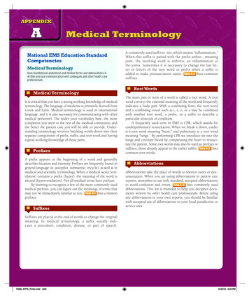
Root Cause Analysis Flow DiagramFigure 1. RCA Process Steps6
Steps to Completing a Root Cause AnalysisStep 1: Charter a TeamTeam composition should be between four and six members. This is founded inthe rationale that the team needs to be large enough to allow diverse viewpointsand opinions (avoiding “groupthink”), but small enough so that meetings do notbecome unwieldy or work deadlines cannot be accomplished.The membership should include: Leader – An individual who is well versed in the RCA process and has therequisite knowledge required to keep the team on track and aligned withthe required components of adverse event investigations. The leader alsoorganizes meetings, assigns roles and ensures that deadlines are met. Advisor – An individual with expertise in the RCA process and the variousmilestone associated with each phase of the team’s work, i.e. flowdiagrams, interviewing, simulation, cause and effect diagramming, finalunderstanding, root/cause contributing factor statement development,action planning, outcome measures and communicating findings toleadership for concurrence. The advisor is not normally present for allmeetings but is available as needed to assist the team. Subject Matter Expert (SME) – An individual possessing intimate familiaritywith the area, domain, clinical discipline, processes and topic beinginvestigated. The SME is often a front-line staff member who is not directlyinvolved in the event. Non-SME – An individual unfamiliar with (naïve to) the specific area,processes, or discipline involved in the adverse event or close call.The charter should, at a minimum, describe the professional title of theindividual and their specific role on the RCA team. Individual names can alsobe provided in the charter memorandum. The following represents anexample depiction of team membership.1.2.3.4.5.6.Director of Biomedical Engineering SMEStaff Nurse Medicine SMEAdministrative Clerk Business Office Non-SMEPhysician Intensivist SME LeaderRespiratory Therapist Team Member RecorderPatient Safety Specialist Team Member Advisor7
Step 2: Conduct Just in Time TrainingTraining conducted during the initial RCA team meeting is especially important for newRCA team members and should be completed with every RCA even if there are nomembers new to the RCA process. NCPS has created a Just in Time training video thatmay be shown at the beginning of each RCA to ensure all team members have abaseline knowledge of the process: Just in Time Training VideoHaving a senior leader greet the RCA team is recommended. This serves to providetangible executive leadership support for the RCA team. The senior leader shouldvalidate the importance of the work ahead and communicate the executive leadership’steam commitment to the process.Just in Time training should provide an overview of the RCA process that includes thefollowing information: Confidentiality. “Any documents or records, which result from this RCA, areconfidential and privileged under the provisions of U.S. Code Title 38 5705, andits implementing regulations. This material cannot be disclosed to anyone withoutauthorization as provided for by that law or its regulations. NOTE: The statuteprovides for fines up to 20,000 for unauthorized disclosures.” Timeline. Once it is determined that an RCA is required for a reported safetyevent, the facility has 45 calendar days to complete the RCA. Roles and responsibilities. It is recommended that the Patient Safety Manager(PSM) not be the leader of the RCA but, be available as the facilitator/advisor tothe group. Additionally, there must be a recorder who will document meetingnotes and interviews. Event briefing. This should be a simple description of what is known about theadverse event at the time of discovery. As the team is briefed, it is likely that theywill have questions about the event. The recorder should document questions asthey arise to guide the team’s next steps. Milestones. Milestones and meeting dates/times should be established at thevery first meeting, enabling team members to block their schedules in advance.This is particularly helpful to those team members who provide direct patientcare, to avoid disruption to clinic schedules or other clinical work.8
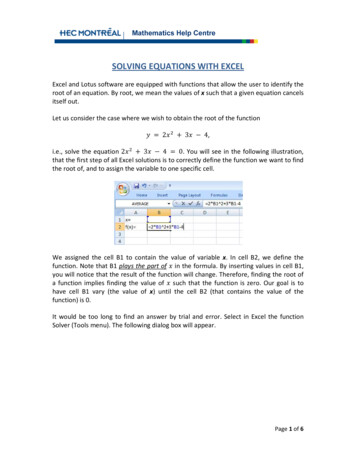
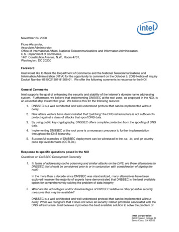
Step 3: Create the Initial Flow DiagramThe Initial Flow Diagram is a graphic representation of the event usingshapes, arrows, and text progressing in stepwise fashion from the firstknown relevant fact through the final known relevant fact. This depictionrepresents a general understanding of the event derived from the JPSRreport and primary fact finding. It identifies missing information and gapsin knowledge which will direct the team's investigation and analysis.The Initial Flow Diagram is the visualization of each known process step up to thepoint in which the system failure occurred. It is an RCA process step that forcesthe team to lay out known and relevant facts of the event, both graphically andchronologically. While there is no single correct way to illustrate the Initial FlowDiagram, normally, this is accomplished using text within shapes and arrows (seeFigure 2). Some additional tools include process maps, swim lane diagrams,post-it note boards, mind maps, cause and effect diagrams, fault trees, and eventtrees.Figure 2. Sample Initial Flow DiagramBeginningStepStepEndIdentifiedinformation gap,question, and/ormissinginformation.The diagram represents the initial work of the team as they determine each stepin the event, where each step is expressed in broad, rather than granular,language. Ultimately, the steps should sequentially flow from one step to the next,to allow a full understanding of what transpired and what elements of the systemrequire improvement. As the team lays out the Initial Flow Diagram and views it inits entirety, it will become apparent that some steps that contribute tounderstanding systems issues may have been omitted; therefore, additional9
information will be required to close gaps in knowledge. The Initial Flow Diagramalso enables the team to answer the “where” and “how” to obtain missinginformation as well as assists the team in identifying the areas of the facility thatneed to be visited, what processes might be simulated, what documents requirereview, and who should be interviewed.The Initial Flow Diagram is different from and complimentary to the InitialUnderstanding, which is expressed in a more detailed narrative form. TheInitial Flow Diagram is constructed after the team meets for work, not before,and therefore is not simply a reproduction of the initial event descriptionretrieved from the patient safety reporting system.Step 4: Craft the Initial UnderstandingThe Initial Understanding is a written narrative of the event progressingchronologically from the first known relevant fact through the final knownrelevant fact that represents a general understanding of the eventderived from the JPSR report and primary fact finding. It identifiesmissing information and gaps in knowledge which will direct the team'sinvestigation and analysis. It will include more detailed information notcaptured in the initial flow diagram.The Initial Understanding is a narrative expression of the RCA team’s work thatproduced the Initial Flow Diagram. This means that the Initial Understanding mayexplain information in greater detail than is possible in the stepwise display in theInitial Flow Diagram. The Initial Understanding should be viewed as separatefrom, and complimentary to, the Initial Flow Diagram.The team should first learn about the context of the event, including staffing,environmental and other influencing factors or data points. This critical work involvesunderstanding and defining what factual events took place leading to an adverse event.It is easy to bring in personal biases. However, assumptions can lead to theoversimplification of the process or missing key steps involved in the adverse event. Byobjectively investigating what happened, the team may find missing information thatchanges the understanding of the event and in turn, helps the team more accuratelyconnect the dots. Medical records should not be pasted into the Initial Understanding,nor should patient, staff, or facility names be included in the iteration. When necessary,position titles may be used to identify staff roles in the process steps.10
Step 5: Identify Information GapsWhile drafting the Initial Understanding, keep the team on task by using a “parking lot”for questions that arise that are not directly associated with the event but may requireanalysis at a later time. Determine what information is missing or needed for completeunderstanding of the event by: Gathering data to gain understanding of the event, the causal factors, andassociated root causes. Ensuring consistent use of the Triage Questions, discussed below, to identifysystem and process vulnerabilities. This allows for continued focus onenvironmental factors and systems rather than people. Continuing to gather data until the team establishes a clear understanding of theevent and the existing factors that led up to it. Visiting the scene of the event and using the event related equipment, if possible,to safely simulate what happened.A thorough review of available information will allow the team to determine what is notknown about the event and what information still needs to be discovered.Step 6: Use Triage QuestionsTriage Questions are a series of standardized questions designed to assistthe team in considering areas of inquiry that might otherwise be missed.Triage questions reveal vulnerabilities in systems and work processes whichhelp RCA teams understand what happened and why. These questions arereferenced throughout the RCA process. Link to Triage Questions.As the definition states, Triage Questions are a standardized set of questions thathelp to ensure the team is carrying out a comprehensive inquiry. All triagequestions should be addressed by the RCA team. Triage Questions areanswered either “yes”, “no”, or “not applicable”; each of these answers assumesthat the question asked was earnestly considered/addressed by the team and isacceptable. Triage Questions may be applied when the team builds the InitialFlow Diagram; however, they can also be referenced throughout the RCAprocess.As the team analyzes the event, they may naturally develop some of their own11
questions to augment the standardized Triage Questions. These “teamquestions” should be combined with the standardized Triage Questions toconduct the investigation and interviews.Step 7: Collect Resources and Prepare for InterviewsOnce the initial sequence of events is mapped out in detail and information gaps havebeen identified using the Triage Questions, the RCA team must specify whatinformation is required to develop a complete analysis of the event. The RCA teamleader should designate individuals responsible for collecting specific information andoutline a timeline for collecting the information. Designated individuals will use the InitialFlow Diagram to determine what information is needed such as, policies, procedures,reports, regulations, directives, pertinent medical record components, etc.When conducting interviews, inform the interviewee of the RCA process and itsprotections (38 U.S.C. 5705). Be clear that the RCA team hopes to learn aboutsystems issues and solutions from the interview. The team should be aware andsensitive to staff member feelings about the event, including fear of blame andrepercussions. The team must account for potential recall or hindsight bias during theinterview process. The interviewee should be encouraged to “tell their story”.Step 8: Conduct the Safety InvestigationFact-finding involves asking “where, what, how, when, and why” using the TriageQuestions as a guide. An RCA team focuses on systems issues and not individualperformance. If possible, to do so in a safe manner and without affecting patient care,the team should visit the site of and simulate the event. After fact finding is complete,the team will complete a Final Flow Diagram, incorporating the new information learned.The PSM may request a data search from NCPS to review previous RCAs, aggregateRCAs, and other related information relevant to the event to determine if pertinentactions were implemented and effective. The team will create a record of thedocuments, websites, and materials used for fact finding to include information receivedfrom other organizations (The Joint Commission, NCPS, Falls workgroups, NationalVHA program offices, etc.).12
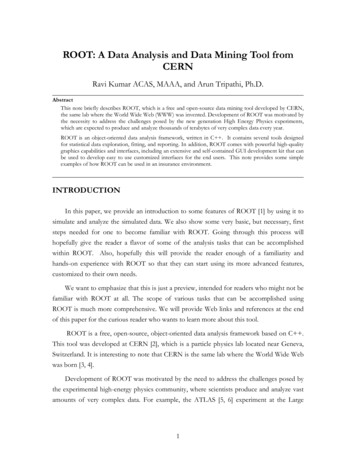
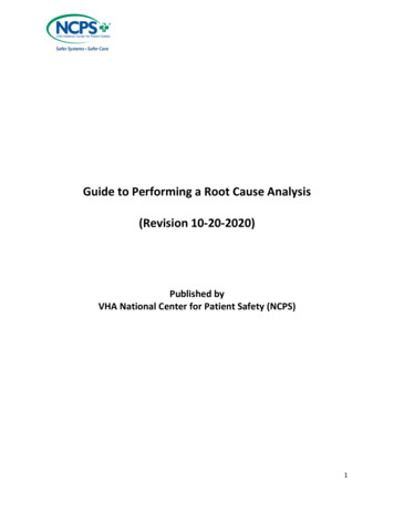
Step 9: Create the Final Flow DiagramThe Final Flow Diagram is a graphic representation of the event usingshapes, arrows, and text progressing in step wise fashion from the firstknown relevant fact through the final known relevant fact. This depictionrepresents a complete understanding of the event derived frominterviews, simulations, document reviews, literature review, and analysisconducted by the RCA team. It addresses missing information and gapsin knowledge identified in the initial understanding and informs the rootcause/contributing factor statements that follow.The Final Flow Diagram follows the same graphic constructs used for the InitialFlow Diagram – that is shapes, arrows, and text. Because the Final FlowDiagram is constructed from the investigative work completed by the RCA team(interviews, simulations, document reviews, literature review, and analysis), it ismarkedly different in detail and appearance from the Initial Flow Diagram (seeFigure 3). Once the final flow diagram is complete, the RCA team will be able toview the event in its entirety and compare what happened to what should havehappened. The team is able to visualize the deviations, formulate anunderstanding, and answer why deviations occurred. If further questions arise,the team may need to do more investigative work, such as follow up interviews ordocument review for clarification.13
Figure 3. Sample Final Flow Diagram14
Step 10: Craft the Final UnderstandingThe Final Understanding is a written narrative of the event progressingchronologically from the first known relevant fact through the final knownrelevant fact that represents a complete understanding of the event,derived from interviews, simulations, document reviews, literature review,and analysis conducted by the RCA team. It addresses missinginformation and gaps in knowledge identified in the initial understandingand informs the root cause/contributing factor statements that follow. It willinclude more detailed information not captured in the final flow diagram.The Final Understanding is a narrative expression of the RCA team’s work thatinformed the Final Flow Diagram. This means that the Final Understanding willexplain information in greater detail than is possible in the stepwise depiction inthe Final Flow diagram. While the Final Understanding expresses the same workproduct, it should be viewed as separate from, and complimentary to, the FinalFlow Diagram.The Final Understanding will provide a comprehensive insight into the story or processresulting in a patient safety event as well as address information gaps, deficiencies, andquestions.When the Final Understanding is complete and includes all analytical work, theteam can move to the next step of the RCA process, developing a Cause andEffect Diagram and synthesizing Root Cause and Contributing Statements.Step 11: Create the Cause and Effect DiagramA Cause and Effect Diagram is a systematic method of determiningcausal links, showing a primary effect of consequence, workingbackwards with "caused by" statements for specific actions andconditions until a reasonable preceding cause or contributing factor canno longer be identified.The Cause and Effect Diagram is a required method of determining causation thatis applied after the team has constructed the Final Understanding of the event.The diagram begins with a Primary Effect of Consequence – this is the problemstatement and starting point for the diagram representing that which should be15
prevented from occurring/recurring. The diagram works backwards using the term“caused by” or “why”. It is important to identify at least two causes, one an actioncause, the other a condition cause for the Primary Effect of Consequence.Actions relate to causes that are in motion, or in an active state. Action causesare momentary in nature and are easily recognizable. For example, using thesimple example of fire, an action cause could be the striking of a match or theplacement of a combustible material near an ignition source. Conditions, on theother hand, are those causes that are passive in nature, often unseen or existingquietly in the background that receive little thought or consideration. Conditioncauses exist over time prior to an action. In the case of fire, conditions would bean oxygen rich environment (air), an existing object made of combustible material(matches), and the presence of an ignition source (tip of match). The actionoccurring within the condition set in the same relative time and space creates thePrimary Effect of Consequence (fire). The Cause and Effect diagram for thisexample is shown in Figure 4.Figure 4. Primary Effect of Consequence, Actions, ConditionsAs a Cause and Effect Diagram works backwards from the Primary Effect ofConsequence, the causes identified may become effects from which the teamcontinues to work backwards, identifying additional causes. Each time the teamasks the question “caused by” or “why”, it identifies more causes in the form ofactions and/or conditions. This results in an ever-expanding set of causes (seeFigure 5). Subsequently, the question becomes where the team should stop16
when constructing a Cause and Effect Diagram.The stopping point occurs when reaching a point of ignorance (“the team doesn’tknow, it just is”), or when there is neither interest nor a rational reason to continueexploring (“who cares?”). For example, if a condition identified is gravity, the teamcould say a point of ignorance has been reached and it makes no sense tocontinue asking why. If a condition identified is snowy winter weather, asking whyand following through with additional causal inquiries is a fruitless exercise atbest. It is important to remember that the more disciplined the RCA team isidentifying action and condition causes for each effect, the deeper the team’sunderstanding of the problem and contributing factors.C/ECBFigure 5. Ever-Expanding Sets of CausesC/ECBCBC/ECBC/ECBC/ECBC/ECBCause /Effect(C/E)CBC/EActionCBC/EC/EPrimaryEffect ofConsequenceCBCaused by /EC/ECause/Effect(C/E)CBC/ECBC/ECBC/EThe methodology described here is a guideline. Not all identified causes andeffects fit neatly into a perfectly linear and symmetrical model such as the onepresented in Figure 5. The team may find as they move deeper into causation,17
there may not always be an identifiable action and condition. On the other hand,there may be multiple actions and/or conditions identified. To stay on the righttrack, the RCA team must identify the Primary Effect of Consequence, thenidentify at least one action cause and one condition cause. The team cancontinue asking “why” to develop the diagram. Figure 6 is an example of a Causeand Effect diagram published by the National Patient Safety Foundation (2016).Figure 6. Sample Cause and Effect Diagram18
Step 12: Identify Root Causes and Craft Contributing Factor StatementsRoot Cause and Contributing Factor Statements are formalstatements that synthesize the RCA team's findings depicted in theFinal Understanding and Cause and Effect Diagram and identify whatsystem elements must be improved.Root Cause/Contributing Factor Statements (RC/CF) identify what systemvulnerabilities contributed to the adverse event or close ca
health care system, adverse public perception of an organization, and litigation. They can also deeply affect health care professionals who are dedicated to the well-being of their patients. Most failures are the result of system and process flaws. These flaws are often not immediately a