Transcription
Computed Tomography(part I)Yao WangPolytechnic University, Brooklyn, NY 11201Based on J. L. Prince and J. M. Links, Medical Imaging Signals andSystems, and lecture notes by Prince. Figures are from the textbook.
Lecture Outline Instrumentation– CT Generations– X-ray source and collimation– CT detectors Image Formation– Line integrals– Parallel Ray Reconstruction EL5823 CT-1Radon transformBack projectionFiltered backprojectionConvolution backprojectionImplementation issuesYao Wang, NYU-Poly2
Limitation of Projection Radiography Projection radiography– Projection of a 2D slice along one direction only– Can only see the “shadow” of the 3D body CT: generating many 1D projections in different angles– When the angle spacing is sufficiently small, can reconstruct the2D slice very wellEL5823 CT-1Yao Wang, NYU-Poly3
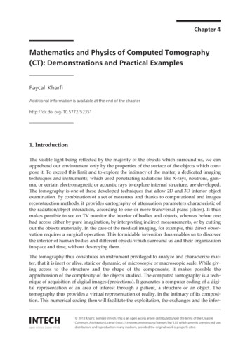
1st Generation CT: Parallel ProjectionsEL5823 CT-1Yao Wang, NYU-Poly4
2nd GenerationEL5823 CT-1Yao Wang, NYU-Poly5
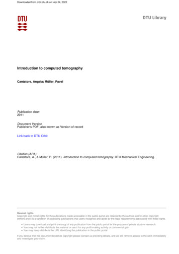
3G: Fan BeamMuch faster than 2GEL5823 CT-1Yao Wang, NYU-Poly6
4GFastCannot usecollimator atdetector, henceaffected byscatteringEL5823 CT-1Yao Wang, NYU-Poly7
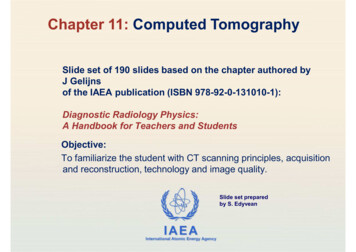
5G: Electron Beam CT (EBCT)Stationary source and detector.Used for fast (cine) whole heart imagingSource of x-ray moves around by steering an electronbeam around X-ray tube anode.EL5823 CT-1Yao Wang, NYU-Poly8
6G: Helical CTEntire abdomen or chest can be completed in 30 sec.EL5823 CT-1Yao Wang, NYU-Poly9
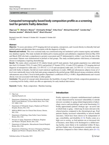
7G: MultisliceFrom http://www.kau.edu.sa/Files/0008512/Files/19500 2nd presentation final.pdfEL5823 CT-1Yao Wang, NYU-Poly10
From http://www.kau.edu.sa/Files/0008512/Files/19500 2nd presentation final.pdfReduced scan time and increased Z-resolution (thin slices)Most modern MSCT systems generates 64 slices per rotation, can imagewhole body (1.5 m) in 30 sec.EL5823 CT-1Yao Wang, NYU-Poly11
GenerationSourceSource CollimationDetector1stSingle X-ray TubePencil BeamSingle2ndSingle X-ray TubeFan Beam (not enough to cover FOV)Multiple3rdSingle X-ray TubeFan Beam (enough to cover FOV)ManyFan Beam covers FOVStationaryRing ofDetectors4thSingle X-ray Tube5thMany tungstenanodes in singlelarge tubeFan BeamStationaryRing ofDetectors6th3G/4G3G/4G3G/4GCone BeamMultiplearray ofdetectors7thSingle X-ray TubeFrom http://www.kau.edu.sa/Files/0008512/Files/19500 2nd presentation final.pdfEL5823 CT-1Yao Wang, NYU-Poly12
From http://www.kau.edu.sa/Files/0008512/Files/19500 2nd presentation final.pdfEL5823 CT-1Yao Wang, NYU-Poly13
X-ray SourceEL5823 CT-1Yao Wang, NYU-Poly14
X-ray DetectorsConvert detected photons to lightsConvert light to electric currentEL5823 CT-1Yao Wang, NYU-Poly15
CT Measurement ModelEL5823 CT-1Yao Wang, NYU-Poly16
EL5823 CT-1Yao Wang, NYU-Poly17
CT NumberNeed 12 bits to representEL5823 CT-1Yao Wang, NYU-Poly18
Parameterization of a LineEach projection line isdefined by (l,θ)yA point on this line (x,y) canbe specified with two optionssOption 1 (parameterized by s):xOption 2: lEL5823 CT-1Yao Wang, NYU-Poly19
Line Integral: parametric formEL5823 CT-1Yao Wang, NYU-Poly20
Line Integral: set formEL5823 CT-1Yao Wang, NYU-Poly21
Physical meaning of “f” & “g”EL5823 CT-1Yao Wang, NYU-Poly22
What is g(l,θ)?EL5823 CT-1Yao Wang, NYU-Poly23
Example Example 1: Consider an image slice which contains asingle square in the center. What is its projections along0, 45, 90, 135 degrees? Example 2: Instead of a square, we have a rectangle.Repeat.EL5823 CT-1Yao Wang, NYU-Poly24
SinogramEL5823 CT-1Yao Wang, NYU-Poly25
Backprojection The simplest method for reconstructing an image from aprojection along an angle is by backprojection– Assigning every point in the image along the line defined by (l,θ) theprojected value g(l, θ), repeat for all l for the given θysxEL5823 CT-1Yao Wang, NYU-Poly26
EL5823 CT-1Yao Wang, NYU-Poly27
Two Ways of Performing Backprojection Option 1: assigning value of g(l, θ) to all points on the line (l, θ)– g(l, θ) is only measured at certain l: ln n Δl– If l is coarsely sampled (Δl is large), many points in an image will not beassigned a value– Many points on the line may not be a sample point in a digital image Option 2: For each θ, go through all sampling points (x,y) in animage, find its corresponding “l x cos θ y sin θ”, take the g valuefor (l, θ)– g(l, θ) is only measured at certain l: ln n Δl– must interpolate g(l, θ) for any l from given g(ln, θ) Option 2 is better, as it makes sure all sample points in an image areassigned a value For more accurate results, the backprojected value at each pointshould be divided by the length of the underlying image in theprojection direction (if known)EL5823 CT-1Yao Wang, NYU-Poly28
Backprojection SummationReplaced by asum in practiceEL5823 CT-1Yao Wang, NYU-Poly29
Implementation IssuesFrom L. Parra at CUNY, d-imaging/lecture4.pdfEL5823 CT-1Yao Wang, NYU-Poly30
Implementation: Projection To create projection data using computers, also has similar problems.Possible l and q are both quantized. If you first specify (l,q), then find (x,y)that are on this line. It is not easy. Instead, for given q, you can go throughall (x,y) and determine corresponding l, quantize l to one of those you wantto collect data.Sample matlab code (for illustration purpose only)N ceil(sqrt(I*I J*J)) 1;N0 floor((N-1)/2);ql 1;G zeros(N,180);for phi 0:179for (x -J/2:J/2-1; y -I/2:I/2-1)l x*cos(phi*pi/180) y*sin(phipi/180);l round(l/ql) N0 1;If (l 1) && (l N)G(l,phi 1) G(l,phi 1) f(x J/2 1,y I/2 1);EndendendEL5823 CT-1Yao Wang, NYU-Poly31
Example Continue with the example of the image with a square inthe center. Determine the backprojected image fromeach projection and the reconstruction by summingdifferent number of backprojectionsEL5823 CT-1Yao Wang, NYU-Poly32
Problems with Backprojectionà BlurringEL5823 CT-1Yao Wang, NYU-Poly33
Projection Slice Theorem G( ρ ,θ ) g (l ,θ ) exp{ j 2πρl}dl The Fourier Transform of a projection at angle θ is a line in theFourier transform of the image at the same angle.If (l,θ) are sampled sufficiently dense, then from g (l,θ) weessentially know F(u,v) (on the polar coordinate), and by inversetransform can obtain f(x,y)!EL5823 CT-1Yao Wang, NYU-Poly34
Illustration of the Projection SliceTheoremEL5823 CT-1Yao Wang, NYU-Poly35
Proof Go through on the boardUsing the set form of the line integralSee Prince&Links, P. 198 G( ρ ,θ ) g (l ,θ ) exp{ j 2πρl}dl EL5823 CT-1Yao Wang, NYU-Poly36
The Fourier Method The projection slice theorem leads to the followingconceptually simple reconstruction method– Take 1D FT of each projection to obtain G(ρ,θ) for all θ– Convert G(ρ,θ) to Cartesian grid F(u,v)– Take inverse 2D FT to obtain f(x,y) Not used because– Difficult to interpolate polar data onto a Cartesian grid– Inverse 2D FT is time consuming But is important for conceptual understanding– Take inverse 2D FT on G(ρ,θ) on the polar coordinate leads tothe widely used Filtered Backprojection algorithmEL5823 CT-1Yao Wang, NYU-Poly37
Filtered Backprojection Inverse 2D FT in Cartesian coordinate:f ( x, y ) F (u , v)e j 2π ( xu yv ) dudvInverse 2D FT in Polar coordinate:f ( x, y) π G(ρ,θ) lF ( ρ cos θ , ρ sin θ )e j 2πρ ( x cosθ y sinθ ) ρdρdθ0 2 0 Proof of filtered backprojection algorithmInverse FTEL5823 CT-1Yao Wang, NYU-Poly38
Filtered Backprojection Algorithm Algorithm:– For each θ Take 1D FT of g(l,θ) for each θ - G(ρ,θ)Frequency domain filtering: G(ρ,θ) - Q(ρ,θ) ρ G(ρ,θ)Take inverse 1D FT: Q(ρ,θ) - q(l,θ)Backprojecting q(l,θ) to image domain - bθ(x,y)– Sum of backprojected images for all θEL5823 CT-1Yao Wang, NYU-Poly39
Function of the Ramp Filter Filter response:– c(ρ) ρ – High pass filter G(ρ,θ) is more denselysampled when ρ is small, andvice verse The ramp filter compensatefor the sparser sampling athigher ρEL5823 CT-1Yao Wang, NYU-Poly40
Convolution Backprojection The Filtered backprojection method requires taking 2 Fouriertransforms (forward and inverse) for each projection Instead of performing filtering in the FT domain, perform convolutionin the spatial domain Assuming c(l) is the spatial domain filter– ρ - c(l)– ρ G(ρ,θ) - c(l) * g(l,θ) For each θ:– Convolve projection g(l,θ) with c(l): q(l,θ) g(l,θ) * c(l)– Backprojecting q(l,θ) to image domain - bθ(x,y)– Add bθ(x,y) to the backprojection sum Much faster if c(l) is short– Used in most commercial CT scannersEL5823 CT-1Yao Wang, NYU-Poly41
EL5823 CT-1Yao Wang, NYU-Poly42
Step 1: ConvolutionEL5823 CT-1Yao Wang, NYU-Poly43
Step 2: BackprojectionEL5823 CT-1Yao Wang, NYU-Poly44
Step 3: SummationEL5823 CT-1Yao Wang, NYU-Poly45
Ramp Filter DesignEL5823 CT-1Yao Wang, NYU-Poly46
Practical Implementation Projections g(l, θ) are only measured at finite intervals– l nτ;– τ chosen based on maximum frequency in G(ρ,θ), W 1/τ 2W or τ 1/2W (Nyquist Sampling Theorem) W can be estimated by the number of cycles/cm in the projection direction in the most detailedarea in the slice to be scanned For filtered backprojection:– Fourier transform G(ρ,θ) is obtained via FFT using samples g(nτ, θ)– If N sample are available in g, 2N point FFT is taken by zero padding g(nτ, θ) For convolution backprojection– The ramp-filter is sampled at l nτ– Sampled Ram-Lak Filter 1 / 4τ 2 ; 2c(n) 1 / (nπτ ) ; 0; EL5823 CT-1n 0n oddn evenYao Wang, NYU-Poly47
The Ram-Lak Filter (from [Kak&Slaney])EL5823 CT-1Yao Wang, NYU-Poly48
Common Filters Ram-Lak: using the rectangular windowShepp-Logan: using a sinc windowCosine: using a cosine windowHamming: using a generalized Hamming windowSee Fig. B.5 in A. Webb, Introduction to biomedicalimagingEL5823 CT-1Yao Wang, NYU-Poly49
Matlab Implementation MATLAB (image toolbox) has several built-in functions:– phantom: create phantom images of size NxNI PHANTOM(DEF,N) DEF ‘Shepp-Logan’,’Modified Shepp-Logan’Can also construct your own phantom, or use an arbitrary image– radon: generate projection data from a phantom Can specify sampling of θR RADON(I,THETA)The number of samples per projection angle sqrt(2) N– iradon: reconstruct an image from measured projections Uses the filtered backprojection method Can choose different filters and different interpolation methods forperforming backprojection[I,H] IRADON(R,THETA,INTERPOLATION,FILTER,FREQUENCY SCALING,OUTPUT SIZE)– Use ‘help radon’ etc. to learn the specifics– Other useful command: imshow, imagesc, colormapEL5823 CT-1Yao Wang, NYU-Poly50
Summary Different generations of CT machines:– Difference and pros and cons of each X-ray source and detector design– Require (close-to) monogenic x-ray source Relation between detector reading and absorption properties of theimaged slice– Line integral of absorption coefficients (Radon transform) Reconstruction methods––––Backprojection summationFourier method (projection slice theorem)Filtered backprojectionConvolution backprojectionEquivalent, but differ incomputation Impact of number of projection angles on reconstruction imagequality Matlab implementationsEL5823 CT-1Yao Wang, NYU-Poly51
Reference Prince and Links, Medical Imaging Signals and Systems,Chap 6. Webb, Introduction to biomedical imaging, Appendix B. Kak and Slanley, Principles of ComputerizedTomographic Imaging, IEEE Press, 1988. Chap. 3– Electronic copy available athttp://www.slaney.org/pct/pct-toc.html Good description of different generations of CTmachines– http://www.kau.edu.sa/Files/0008512/Files/19500 2nd presentation final.pdf– d-imaging/lecture4.pdfEL5823 CT-1Yao Wang, NYU-Poly52
Homework Reading:– Prince and Links, Medical Imaging Signals and Systems, Chap6, Sec.6.1-6.3.3 Note down all the corrections for Ch. 6 on your copy ofthe textbook based on the provided errata. Problems for Chap 6 of the text book:– P6.5– Consider a 4x4 image that contains a diagonal lineI [0,0,0,1;0,0,1,0;0,1,0,0;1,0,0,0]; a) determine its projections in the directions: 0, 45,90,135 degrees. b) determine the backprojected image from each projection; c) determine the reconstructed images by using projections in the 0and 90 degrees only. d) determine the reconstructed images by using all projections.Comment on the difference from c).EL5823 CT-1Yao Wang, NYU-Poly53
Computer AssignmentDue: Two weeks from lecture date1.2.3.4.Learn how do ‘phantom’.’radon’,’iradon’ work; summarize theirfunctionalities. Type ‘demos’ on the command line, then select ‘toolbox image processing - transform - reconstructing an image fromprojection data’. Alternatively, you can use ‘help’ for each particularfunction.Write a MATLAB program that 1) generate a phantom image (you can usea standard phantom provided by MATLAB or construct your own), 2)produce projections in a specified number of angle, 3) reconstruct thephantom using backprojection summation; Your program should allow theuser to specify the number of projection angle. Run your program withdifferent number of projections for the same view angle, and the differentview angles, and compare the quality. You should NOT use the ‘radon( )’and ‘iradon()’ function in MATLAB.Repeat 1 but uses filter backprojection method for step 3). In addition tothe number of projection angles, you should be able to specify the filteramong several filters provided by Matlab and the interpolation filters usedfor backprojection. Compare the reconstructed image quality obtained withdifferent filters and interpolation methods for the same view angle andnumber of projections. You can use the “iradon()” function in MATLAB(Optional) Repeat 3 but uses convolution backprojection method. Youhave to do your own program.EL5823 CT-1Yao Wang, NYU-Poly54
Computed Tomography (part I) Yao Wang Polytechnic University, Brooklyn, NY 11201 Based on J. L. Prince and J. M. Links, Medical Imaging Signals and Systems, an