Transcription
Switchgear Internal Arc ProtectionIn Correlation With Arc FlashEngr Dionisio N. Bacudio Jr., PEE
AGENDA1Overview of LV and HV Switchgears2Understanding Internal Arc3IEC TR on Internal Arc for LV Swgr4LV Swgr Internal Arc Protection Design5IEC Standard for HV Switchgearon Internal Arc6Design on Internal Arc protection forHV Switchgears7Arc Flash Protection
1. Overview of LV andHV Switchgears
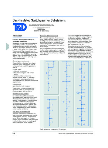
Electrical Distribution System -SLD HV Switchgear Electrical SCADA / EMCS / PMS Transformers – Cast Resin, Oil Main LV Panels – up to 6300A Synchronizing Panels, ATS Panels Motor Control Centers Sub Main Switchboards Final Distribution Boards Power Factor Correction & Harmonic Filtering
LV Switchgear Overview
A single architecture1122FrameBusbars33 Power Connection44Drawer
Additional Letter and Supplementary letter
Form Separation of LV Switchgear
Form Separation of LV Switchgear
HV Switchgear OverviewPage 11
HV Switchgear OverviewPage 12
HV Switchgear Overview - SLDPage 13
2. Understanding Internal Arc
Effect of Internal ArcInternal arc withstand is variouslynamed: internalarc withstand arc fault containment anti arc DesignPage 15 Control of the effects of arcing faults withinswitchgear or other equipment, to protect theoperator and (if appropriate) the general public frombeing injured. Prevention of internal faults through modern designpractice, can reduce risk but cannot completelyeliminate the possibility of faults. Fast acting protection systems can minimize theeffects of arc flash. Elimination of flammable materials would alsoreduce risk. A ‘Vented Cubicle’ is NOT necessarily able towithstand internal arc faults.
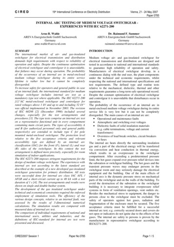
Origins and consequences of an internal faultsOrigins:Consequences: Significant overheating(temperature at the core of the arc around20,000 C)Forced inter-locks Production of hot gases and burning particles Overvoltages due to lightning Increase in pressure Faulty protection system operation Deterioration and projection of parts Faulty component Tools forgotten after maintenance Very corrosive atmosphere Page 16
Other causes the arc flashInsulation breakthrough in switchgear: Not likely but still possible in severe over voltage case Possible even in GISComponent failure: Cable terminal failures CT’s and VT’s Station (auxiliary) transformers Contactors, circuit breakers, Circuit breaker connectorsHuman errors: Falling tools/parts (screws, nuts, etc) Use of wrong tools Misuse Forgotten measurement wires or groundings
Other causes the arc flashBad contacts: Bad contacts (temperature rise/overload) Insufficient tightening moment (Torque) Vibration Over voltagesAnimals: Small animals are often the root cause of arc flash Very hard to preventThere are also arc flash that are out of scope and not to be protectedby arc flash relays. Such an arc flash are as: Vacuum breaker arc flash Arc flash in disconnector Lightning induced arc flash in overhead-lines etc.
Arc flash damages on switchgear Extremely rapid release of energy inform of heat and pressure Arc temperature in rage of 20000 C(three fold surface temperature ofthe Sun) Drastic heat ignite insulation,conductors and metal resulting toxiccompounds molten metal blast
Arc flash damages on switchgear Switchgear damages are typicallyvery big May result to production losses May result to personnel damages
Arc flash damages on switchgear
Arc flash damages on switchgear
Arc flash damages on switchgear
Arc Resistant Switchgear in Action
Incident – Breaker RackingArc Flash racking breaker.wmv
What Kinds of Injuries Can Result?What Kinds of Injuries Can Result?Burn Injuries First Degree – burns epidermis only 2nd Degree – extends deeper; may require skin grafting 3rd degree – requires excision, grafting; severe cases mayrequire amputationBlast Injuries Shrapnel Hearing Damage Pressure wave
Hierarchy of Risk Control Protection (PPE) – least effective Administrative Controls – regulate risk Awareness – reveal risk Engineering Controls – manage & control risk Substitution – replace risk Elimination – remove risk
Arc phenomenonIntense light, burningand blinding radiationVaporized copper(volume 67.000 timessolid copper) Pressure wave Toxic gasesHigh temperatureup to 20.000 CHeated air pressure and soundwave(Air expands 1.600 fold)Shrapnel andmolten metal
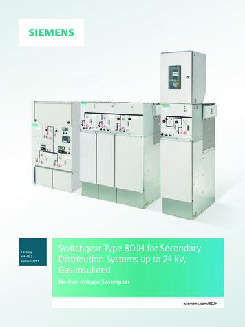
Arc flash damages on switchgearDamage to the switchboard asfunction of current and timeLand, H., Eddins, C., Klimek, J.Evolution of Arc Fault ProtectionTechnology at APL,Johns Hopkins APL TechnicalDigest, Volume 25, Number 2, 2004.
3. IEC TR 61641 Guide fortesting under conditions ofarcing due to Internal Arc
StandardsThe main relevant IEC Standards for LV Switchgear-IEC 61439-1&2: LV Switchgear and Controlgear assembliesIEC 60947-2:LV Circuit breakersIEC 60947-4:LV Contactors and Motor StartersIEC 60529 :Degrees of Protection- IEC 61921:LV Capacitor BanksTechnical Report- IEC 61641 :Internal Arc Fault Containment
The main changesCurrentIEC 60439-XLV switchgear& controlgearAssembliesIEC 61439-XLV switchgear& controlgearAssembliesGeneral rules Power switchgear and controlgear assemblies60439-1Distribution Assemblies forAssemblies forboardsconstruction sites public 2General rulesIEC 61439-1 (Ed.2.0 : 2011)Power switchgear andcontrolgear assemblies61439-2(Ed.2.0 :2011)Distributionboards61439-3(Feb 2012)Assemblies forconstruction sites61439-4(Nov 2012)Assemblies forpublic networks61439-5(Nov 2010)Busbartrunkings61439-6(May2012) ”Power Switchgear and Controlgear Assemblies” are now covered by IEC 61439-2, to beread in conjunction with IEC 61439-1
Certification bodies / Test laboratories
Type Tests and Routine Tests for LV SwgrRoutine tests :They are intended to detect faults inmaterials and workmanship andascertain functioning of the manufacturedASSEMBLY. Construction: n 1 – degree of protection ofenclosures n 2 – clearance and creepagedistances n 3 – protective circuit test n 4 – incorporation of built-incomponents n 5 – internal electrical circuits andconnections n 6 – terminals for externalconductors n 7 – mechanical operation Performance: n 8 – dielectric properties n 9 – wiring, operational performanceand functionPage 3511 Type tests on the prototype: n 1n 2n 3n 4n 5Temperature rise limitsDielectric propertiesShort-circuit withstandProtective circuit effectivenessClearances and creepagedistancesn 6 Mechanical operationn 7 Degree of protectionn 8 Lifting Testn 9 Corrosion resistancen 10 Resistance of insulatingmaterial to normal heatn 11 Resistance of insulatingmaterial to abnormal heatOptional Type Test: Internal Arc Containment
IEC 61641 TR Internal Arc ContainmentThe ability of an ASSEMBLY to pass the test according to thistechnical report is only one aspect.The skill of the personnel having access to the kingprocedures applied, and the conditions in the location wherethe ASSEMBLY is installed, are aspects that need to be takeninto account.
The Typical Internal Arc Fault result from: Conducting materials inadvertently left in ASSEMBLIES duringManufacture, Installation or Maintenance. Faults in Materials or workmanship Entry of vermin (small animals such as mice, snakes, etc). Use of incorrect ASSEMBLIY for the application resulting inoverheating and subsequently an internal arc fault Inappropiate operating condition, or Lack of maintenance Operator errorsPage 37
Assessment of the test:1. Correctly secured doors and covers do not open and remain effectively in placeand provide IP 1X of IEC 605292. No parts of the ASSEMBLY are ejected which have a mass of more than 60gexcept those which are dislodged and fall between the ASSEMBLY and theIndicators.3. Arching does not cause holes to develop in the external parts of the enclosurebelow 2m at the side declared to be accessible as a result of burning.4. The Indicators do not ignite5. The protective circuit for accessible part of the enclosure is still effective inaccordance to IEC61439-26. The ASSEMBLY is capable of confining the arc to the defined area where it wasinitiated.7. After clearing of the fault or after the isolation or disassembly of the affectedfunctionalunits in the defined area, emergency operation of the remainingASSEMBLY is possiblePage 38
Page 39
4. Different Designs forLV SwitchgearInternal Arc Protection
LV Power Switchgear Up to 1000Vac Drawout circuit breakers Grounded metal enclosure Ratings: Continuous current Short-time withstand current Short-circuit withstand current Unless specifically designated, these ratings areestablished based on bolted fault currents(IEEE C37.20.1)Page 41
Square D Power-Zone 4 SwitchgearPage 42
Details are Important!Page 43
Details are Important!Page 44
5. IEC Standard for HV Swgron Internal ArcIEC 622171 - 200
IEC 62271-1 applies to AC switchgear and controlgear for indoorand /or outdoor installation and for operation at servicefrequencies up to and including 60Hz and having voltagesabove1000V. This document applies to all HV switchgear andcontrol gear except as otherwise specified in relevant IECStandards for particular type of switchgear and controlgear.IEC 62271-200 applies to AC switchgear and controlgearPage 46
Page 47
Page 48
Page 49
Page 50
Criteria to Pass the Test1. Doors and Covers do not open, no part comes as far as the indicator or Wall2. No fragmentation of enclosure occurs, no ejection of fragments or of otherparts of the Swgr of an individual of 60 grams.3. Arching does not cause holes by burning through in the classified sides ofup to 2000mm4. Indicators do not ignite due to the effect of the hot gases or burning liquid.5. The enclosure remains connected to its earthing point.Page 51
Test Criteria in IEEE C37.20.7C37.20.7 is a performance-based standard Does not define or mandate design features Sets forth criteria that must be met in order to obtain the classificationIn short, equipment is submitted to internal arcing faults Initiated by a “fuse wire”‒ LV – 2.6mm diameter (#10 AWG)‒ MV – 0.5mm diameter (#24 AWG) Current rated short-time current of the equipment Defined duration – preferred value 0.5 secondsEquipment tested in “service” condition – e.g., configuration is supposed to mimic, as closely aspossible, actual field conditionsProtective devices are allowed to help achieve the AR rating Equipment nameplate must be marked to indicate that they are requiredMarketingFaiz –– OctOct 20132013Marketing–– FaizSchneider Electric - Marketing – Faiz– Oct 2013
Performance Criteria in IEEE C37.20.7Criterion 1: properly latched or secured doors, covers, and so on, do not open.Criterion 2: No fragmentation of the enclosure Ejection of some small parts above 2m height is allowed Criterion 3: No burn-throughCriterion 4: No cotton indicators ignite They are placed outside the gear and near gas exhaust meansCriterion 5: All grounding connections remain effectiveMarketingFaiz –– OctOct 20132013Marketing–– FaizSchneider Electric - Marketing – Faiz– Oct 2013
6. Designs on Internal ArcProtection forHV Switchgears
Partitioning & Nature of barrierCompartments : description of design and function The manufacturer defines the number & contentof compartments Each compartment is described as: design:– fixed– removable– withdrawable– extractible accessibility:––––Page 55interlocked-controlledprocedure basedtools basednone-accessible
HV Switchgear Solution Against Internal ArcingPage 56 Must resist to mechanical and thermalstresses Must protect the operator against anyrisk resulting from the devastating effectsof possible internal arcing The cubicle design allows for arcingeffects to be contained (internalsuppression, mechanical and thermalstress): choice of non-flammable materials channelling of hot gases
HV Switchgear Solution Against Internal ArcingIn addition to the internal arc version, cubicle can beequipped with solutions to limit internal arcingLimits the duration of the fault Mechanical Internal arc detector on the cubicle: Swgr associated with a Sepam relay eliminates thefault in less than 140 ms GasFlaps LinksMicro-contactsSepamRear ofthe cubiclePage 57Front ofthe cubicle
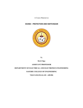
HV Switchgear Solution Against Internal ArcingInstallation exampleSwitchboard against a wall.AFL anti-arcing protectionPage 58Switchboard in the middleof the room.AFLR anti-arcingprotection(acces around the backof the switchboard)Switchboard in a roomwith a ceiling height of lessthan 4 meter
MarketingFaiz –– OctOct 20132013Marketing–– FaizSchneider Electric - Marketing – Faiz– Oct 2013
Solution Against Internal Arc toward the operatorPage 60
Page 61
Exhaust Plenum Plenum Required if: Ceiling less than192” (4.87m) Power ZoneCenter Application Exhaust neededfrom equipmentroom 50kA rating(optional use-arcshield)Page 62
Alternative – “Arc Shield” Arc ShieldRequired if: 50kA rating(optional useplenum) Increaselikelihood ofprotection forfront, rear, &sides ofequipmentPage 63
Equipment Nameplate Must specifically indicate arc-resistant ratings: Accessibility type Internal arcing short-circuit current Arcing duration Type of protective device (when applicable) Rated maximum clearing time for protective device(when applicable) When fuses or fast-acting devices are used, the“DEVICE LIMITED” must appear along with the part #under the “arcing duration”
7. Arc Flash Protection
Arcing Faults Vs Short Circuits Short Circuit – A bolted short circuit picked-up by Circuit breakersand interrupted in few milli-seconds. Internal Arc – Arcing between phases creates a low-current, highimpedance path in open air. generally the low current value cannotbe picked-up by Circuit breakers .results in ionizing the air around itcausing tremendous increase in pressure. Flash hazard – A dangerous condition associated with the release ofenergy caused by an electric arc. In worst cases, a very violent event Signficant heat energy released Significant pressure wave – an explosive event!
TermArc Flash HazardDescriptionA dangerous condition associated with the release of energycaused by an electric arcArcing Fault CurrentA fault current flowing through an electrical arc plasma, also called arcfault current and arc currentBolted Fault CurrentA short circuit or electrical contact between two conduc- tors atdifferent potentials in which the impedance or resistance between the conductors is essentially zeroFlash Hazard AnalysisA method to determine the risk of personal injury as a result ofexposure to incident energy from an electric ArcFlash.Incident EnergyProtection BoundariesThe amount of energy impressed on surface, a certain distance fromthe source, generated during an electrical arc event. Incident energy ismeasured in Joules per cen- timetre squared (J/cm2) or Calories percentimetre squared (cal. /cm²)Boundaries relating to electrical safety when working on energizedequipment. Only qualified personnel can enterthese boundaries which requires appropriate PPEArc Flash BoundaryThe flash protection boundary is the distance from the arc source(energized exposed equipment) at which the po- tential incident heatenergy from an arcing fault falling on the surface of the skin is1.2cal/cm 2. An exposure to 1.2cal/cm2 would normally result in acurable second- degree burn. Within this boundary workers arerequired to wear protective clothing like fire resistant (FR) shirts andpants, and other equipment to cover various parts of the body. Thisdistance may vary from equipment to equipment since it is a function ofthe available fault cur- rent of the system at that point, the voltage andthe trip- ping characteristics of the upstream protective device as wellas some other parameters.
Source: NFPA 70E 2018
Source: NFPA 70E 2018
What is arc flash protection - PPE Arc flash protection can be understood in many waysDoes this protect user in case of arc flash hazard? Yes, maybe, no.Use of PPE gives protection against heat and flying objects but PPE maynot give protection against toxic gases, pressure shock, high soundpressure, falling or slipping, etc.Does PPE protect switchgear against damages? No
MarketingFaiz –– OctOct 20132013Marketing–– FaizSchneiderFaiz–– OctSchneiderElectricElectric- -MarketingDivision -–NameDate201376
Why Arc Flash Protection?Page 77
Page 78
87B Relaying: Sample Schematic
Bus Differential Protection Provides protection for buses and/or switchgear Sum currents into & out of “zone of protection” Normally at or near zero (KCL) Non-zero value indicates presence of fault Favorable characteristics for arc-flash: High-speed ( 20 ms relay operating time) Sensitive Compatible with other types of relaying Proven, familiar technology
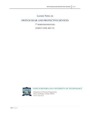
Arc Terminator System Operation Sense a Fault Current Detect an Arc Close Shorting SwitchMAINBREAKERCT'sCURRENTDETECTORSchneider ElectricPage 81- Engineering Services – April 2011ARCDETECTORCONTROLLERSHORTINGSWITCH81
Arc Terminator System BenefitsWhen Properly Configured, MeetsArc Resistant Standards Plus: Reduces incident energy; Arc flash hazard reduction Reduces pressure buildup Reduces release of toxicmaterials Eliminates need for reinforcedswitchgear Eliminates special requirementsfor buildings or plenums Minimizes equipment damage Reduces operating downtimePage 82
Arc Terminator System Operation Section view of an Arc Terminatormounted above a 1200 A circuit breakerin MASTERCLAD switchgear
Arc Terminator System BenefitsReduces Incident Energy; Arc Flash Hazard ReductionNote: Minimum PPE Level is now changed to 1Schneider Electric- Engineering Services – April 201184
HV Switchgear Overview - SLDPage 85
Arc Flash Relay and SensorsPage 86
Arc Flash Relay and SensorsPage 87
Page 88
Page 89
Benefits of Arc Flash Protection Personnel safety Reduces Loss of production Prolonged Switchgear Life cycle Reliable OperationPage 90
MarketingFaiz –– OctOct 20132013Marketing–– FaizSchneiderFaiz–– OctSchneiderElectricElectric- -MarketingDivision -–NameDate201392
Questions
HV Switchgear Solution Against Internal Arcing Switchboard against a wall. AFL anti-arcing protection Switchboard in the middle of the room. AFLR anti-arcing protection (acces around the back of the switchboard) Switchboard in a room with a